Found this in a box of unrelated stuff:
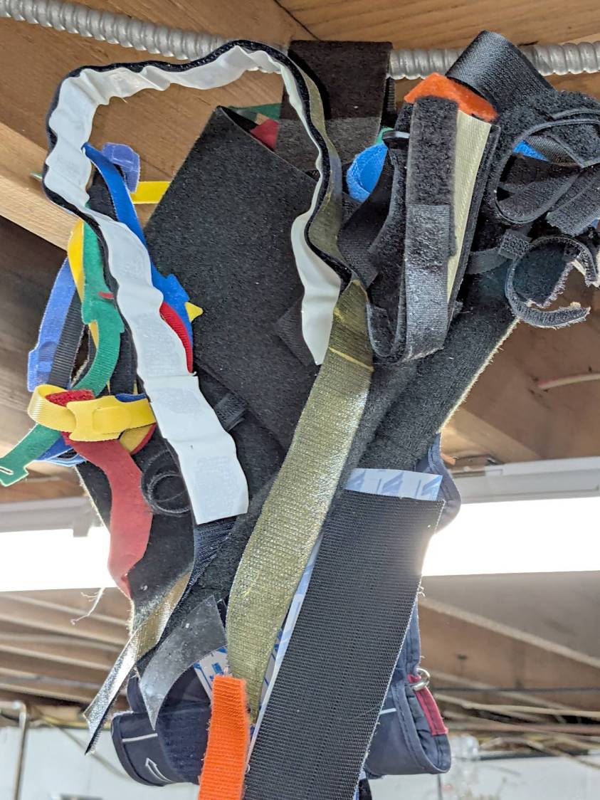
Based on past experience, the longer it hangs there, the bigger it will become.
My packing skillz obviously suffered a blackout during the move …
The Smell of Molten Projects in the Morning
Ed Nisley's Blog: Shop notes, electronics, firmware, machinery, 3D printing, laser cuttery, and curiosities. Contents: 100% human thinking, 0% AI slop.

Found this in a box of unrelated stuff:
Based on past experience, the longer it hangs there, the bigger it will become.
My packing skillz obviously suffered a blackout during the move …
This is a quick-and-ugly test to see how well aluminized Mylar will work as a reflective shade for some LED light bars eventually washing the Living / Sewing room ceiling with enough light to brighten the Sewing Table:
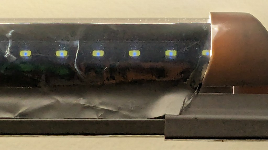
The key question: how well adhesive adheres Mylar to the pleasantly warm aluminum extrusion serving as the heatsink for 40 W of LEDs:
Perhaps surprisingly, those ½ inch strips come from an A4 sheet by way of a paper cutter.
As with the Mylar shades over the COB LED strips in the laser, the LEDs remain through the aluminized layer:
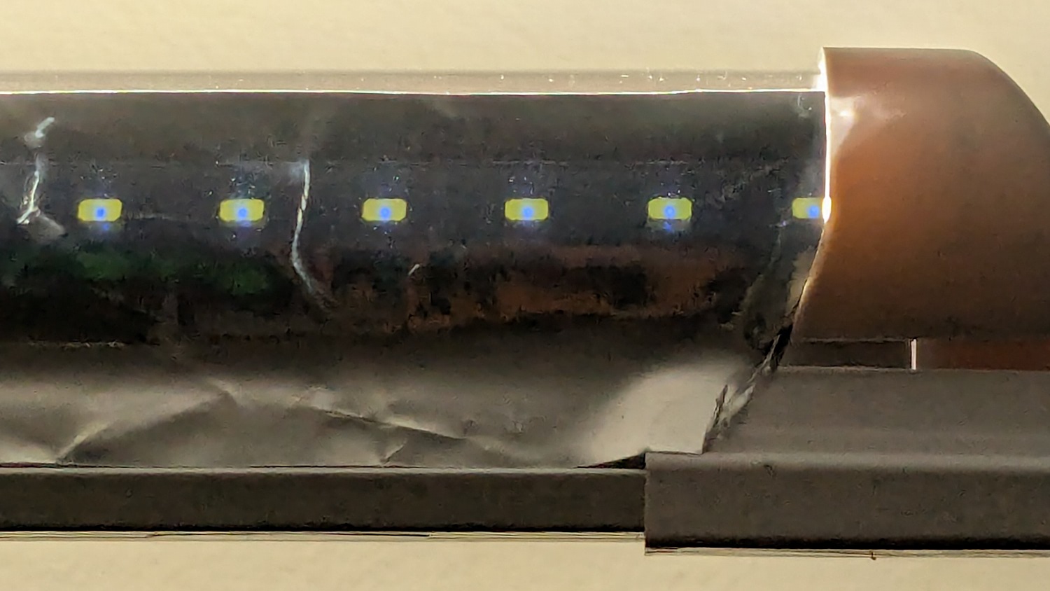
The LED bars will be directly visible, so bouncing the direct light against the wall reduces glare and puts it to good use.
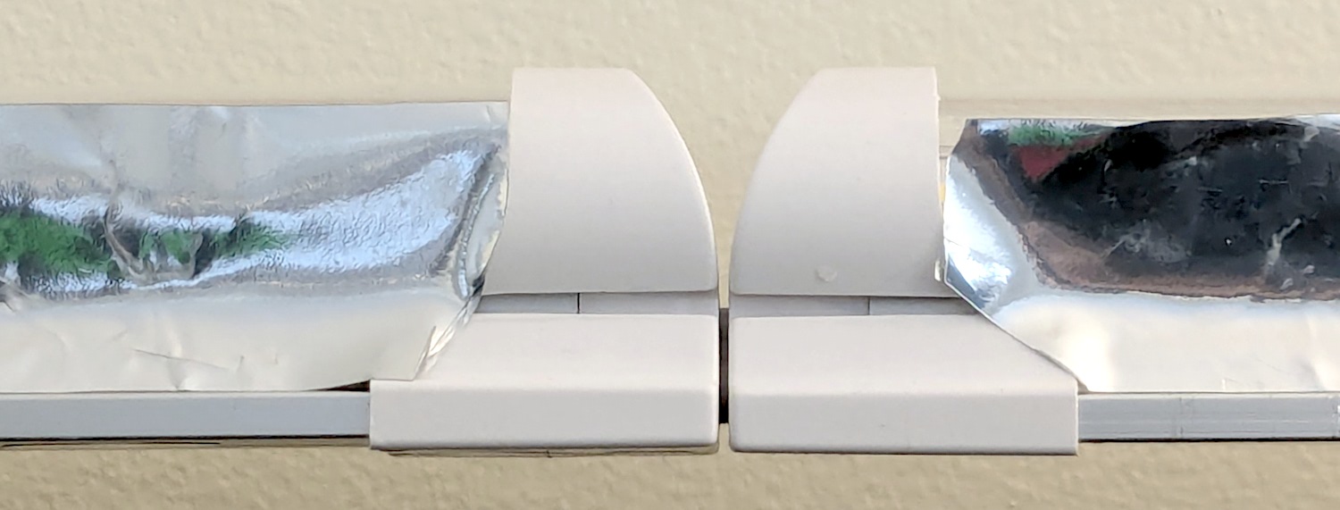
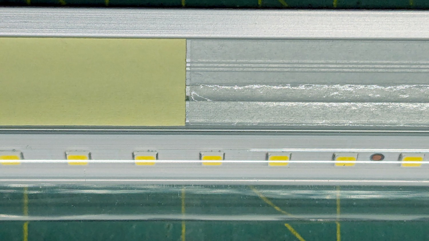
The Mylar strips are 1 inch wide, cut with a utility knife against a straightedge, although ⅞ inch seems adequate. The last LED over on the right sits at the endcap, so I will (try to) tuck the Mylar ends under the caps for a cleaner fit.
The bars have two 4 foot strips of LEDs in series, with a lump of circuitry buried in the aluminum extrusion that seems be a bridge rectifier and a small electrolytic capacitor. There’s not nearly enough capacitance to knock down the 120 Hz flicker and I have an uneasy expectation of stroboscopic effects on the sewing machines.
This is a test. […] This is only a test.
Now, to model angle brackets fitting the strips to the window moulding.
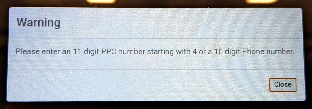
I always suspect there’s a reason behind a missing price label on a shelf, so I waved a half-gallon of milk under a nearby price scanner:

If you’re thinking that white rectangle doesn’t look like a price, you’re right:

A 10 digit Phone number?
I’m don’t know what a “PPC number” is, although the UPC on the milk carton seems perfectly normal:

Admittedly, the number starts with a zero and has 12 digits, so it’s definitely not what the price scanner wants. On the other paw, why is a price scanner not looking for a UPC?
The placard below the display is amusing:

Gray’s variant of Hanlon’s Razor: “Any sufficiently advanced incompetence is indistinguishable from malice.”
No, I neither asked why the scanners didn’t work nor made a phone call, as I’m old enough to know better.
Having herded all the denizens of the Subpixel Zoo into one LightBurn workspace, framing them seemed appropriate:
We had some 18×24 inch frames which fit a standard construction paper size. The paper colors aren’t nearly as vivid as a real artist would want, but they’ll suffice for my simple needs.
Lay out a template and decide 180 mm blocks fill the frame:
Offse the blocks 2 mm outward for cutting clearance and make a fixture:
The outer rectangle matches a blank sheet of corrugated cardboard cut by hand to fit the platform. The inner rectangle marks a line around the 18×24 inch position of the paper, giving me a mark within which I can center the paper well enough by eyeballometric approximation.
Cutting the blocks and marking the lines produces the template:
It’s held in place by four finger-crushingly strong magnets. If I ever do this again, I’ll throttle back on the power for the corner targets, because the laser cannot reach the top speed marking the outline, so it cut through the top layer of cardboard at the targets.
The layers for the 8×8 versions have 170 mm blocks with all the colors properly separated:
Embiggen the blocks to 180×180 mm, rotate them to their new orientation, then snap them into copies of the new template:
I can only envision these things in the landscape orientation that will fit the laser platform, but you could build them in their final portrait orientation and rotate the result.
I put the template pattern in the middle of the LightBurn workspace and use Print and Cut to align the fixture with the corner targets. Then it’s just a sequence of laying a sheet of paper on the fixture, selecting the corresponding layout, hitting P to snap the layout to the center of the workspace, and Firing The Laser.
It’s not nearly as pretty as Mary’s quilts, but now I have a wall decoration of my very own.

Another trivial laser cutter project:
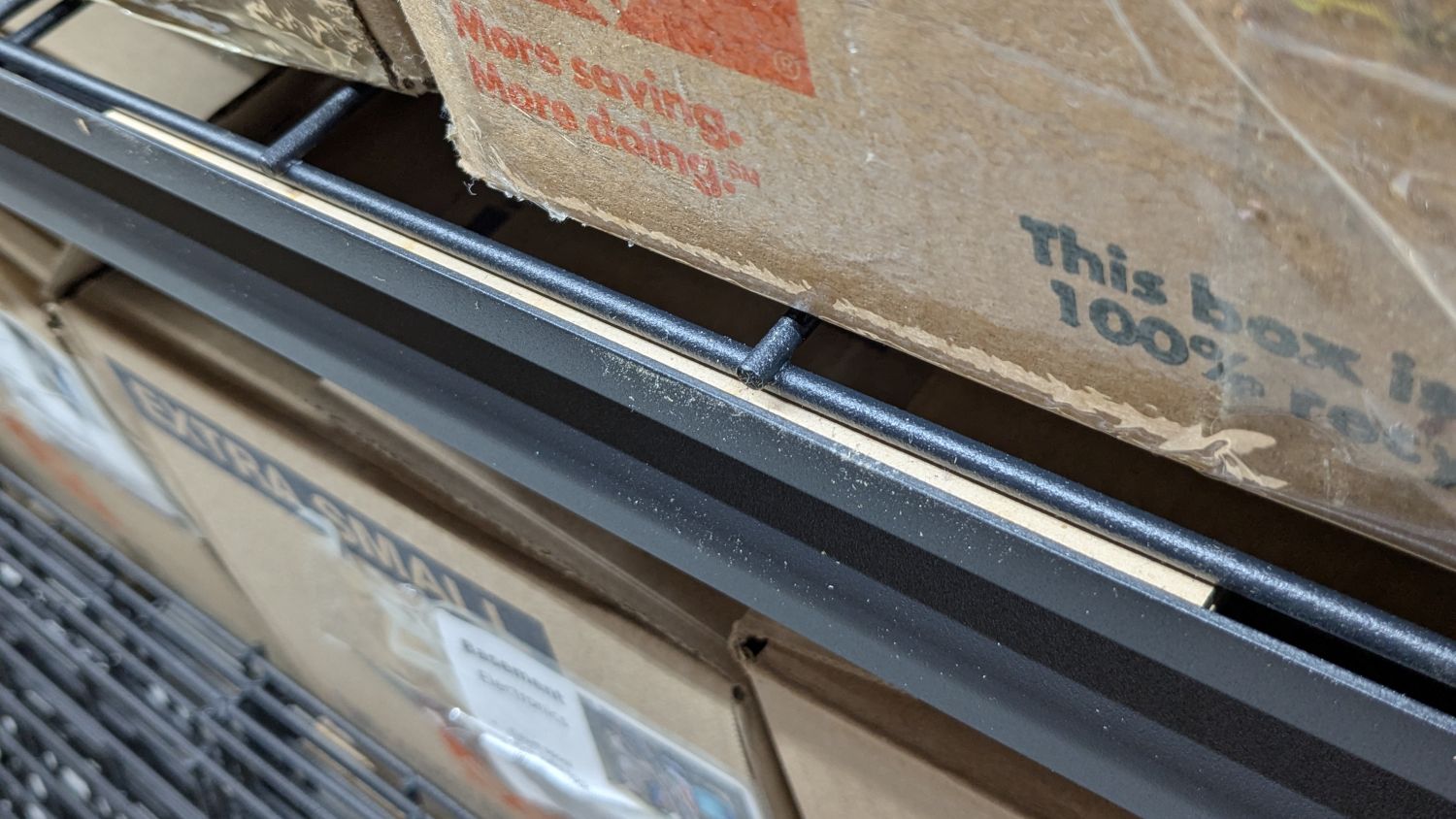
I’m finally assembling the shelves for the last of the boxes cluttering the basement floor. Because the top of the wire shelf grid sits 4 mm below the top of the shelf rails, surely for some good reason, that pale strip is a 6 mm shim raising the grid just enough to let the boxes slide easily off without having to lift them over the rail.
It’s a pair of 3 mm thick MDF strips stuck together with tapeless sticky (a thin adhesive layer on backing paper), with the same adhesive holding the shim to the rail while I lay them down and plunk the shelf grid on top:

I made two sets of shims to fit the support rod spacing, with lengths carefully chosen to match two stacks from my Big Box o’ MDF Cutoffs, all 10 mm wide to fit the shelf rails:
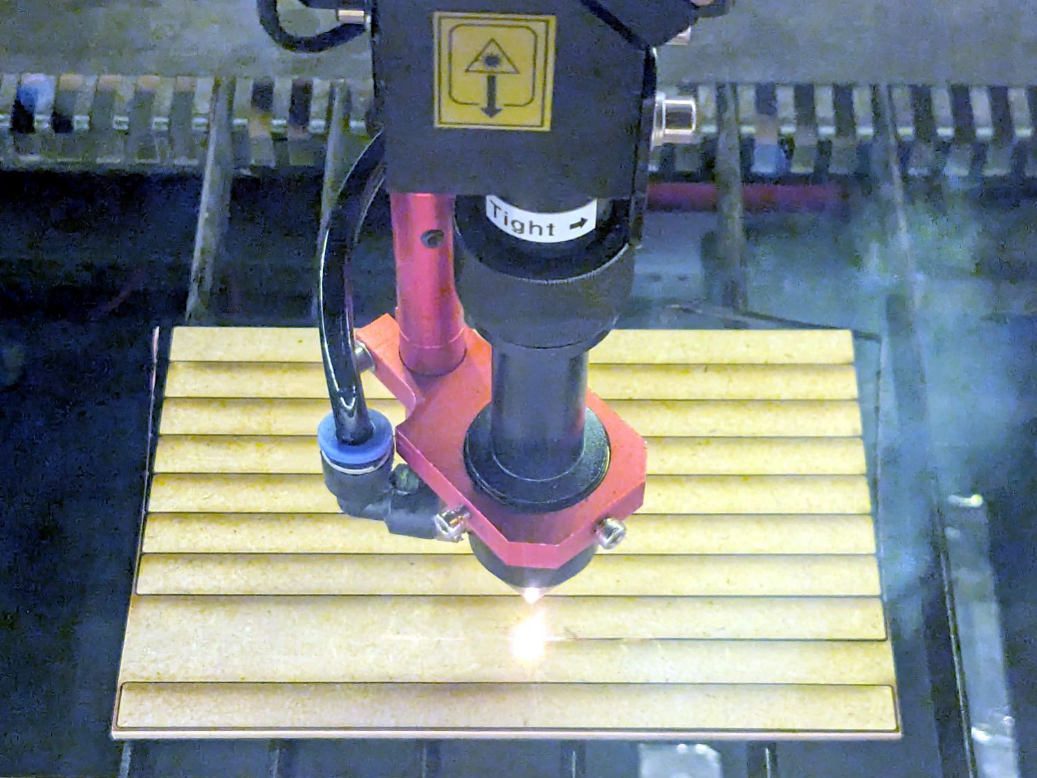
Admittedly, not all of the neatly rounded corners came through, due to slight variations in MDF sizing / Print-and-Cut alignment / whatever, but it’s a nearly zero waste way to turn stock into strips.
Each shelf needs 14 shims = 28 strips and I’m here to tell you if I had to bandsaw 140 little strips for each of three sets of shelves, well, I:
Watching that thing never gets old …

Having once again reawakened a back injury from long ago, I figured these were good for some comic relief:

The full-scale L4-L5 vertebrae are from Printables and the ¾ scale L5 is from somewhere I cannot recall. A mother lode of anatomical models is on Thingiverse if you want some 3D printing challenges.
The L4-L5 pair are part of an extensive human anatomic model locating all the pieces at their proper coordinates, so these two hovered about 800 mm above the XY plane. I ran them through the Grid:Tool mesh editor to center them at the XY origin, then put the bottom-most point at Z=0.
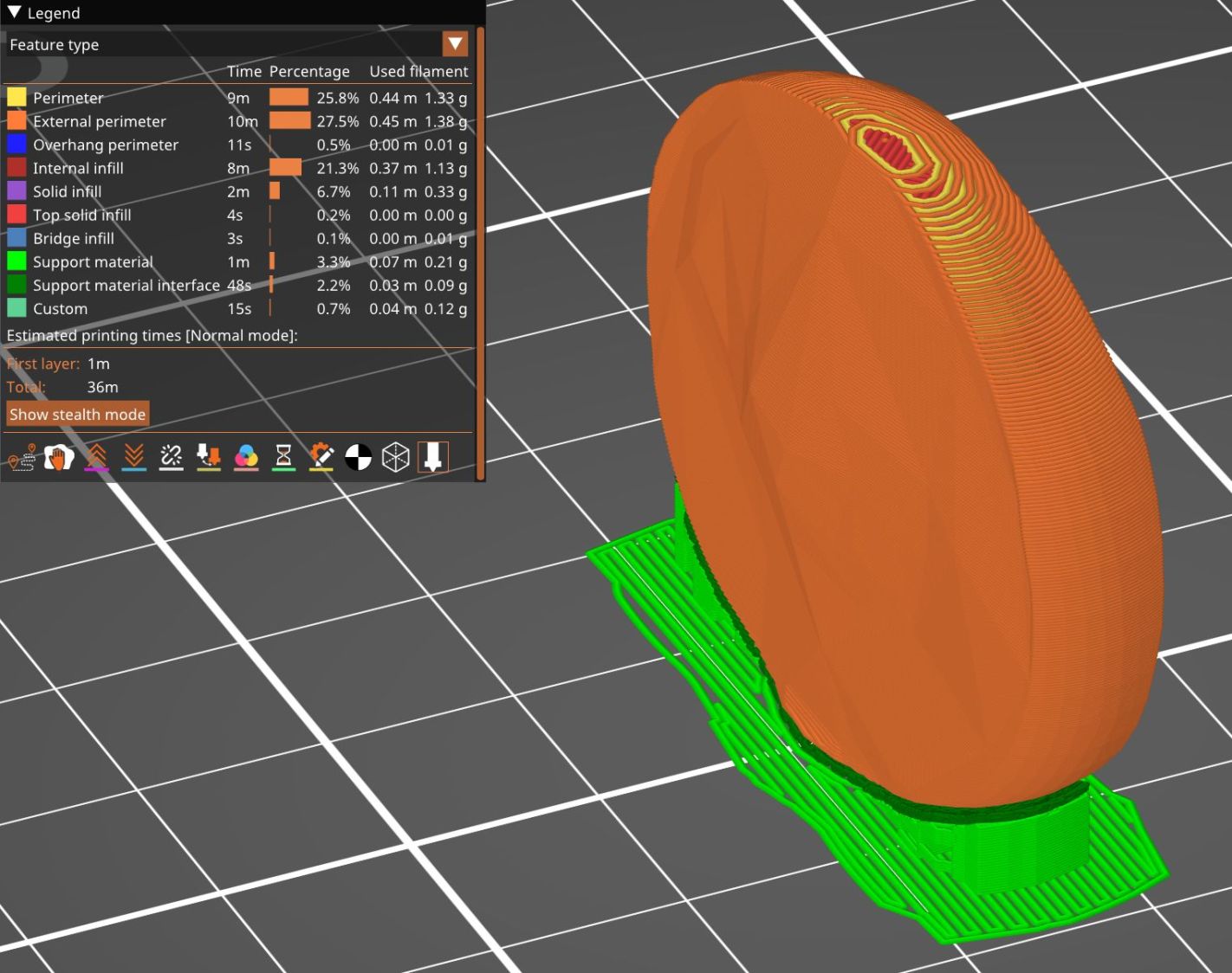
Rotating them individually in PrusaSlicer and painting only the most essential support got them to this state:

Each one take about three hours, so I ran them individually to reduce surface blemishes and maximize the likelihood of happy outcomes. Worked like a champ.
The retina-burn orange disk is not anatomically correct, because the InterWebz apparently does not have a model for spinal cartilage:

Instead, it’s a rounded cylinder resized into an oval, with its top and bottom surfaces formed by subtracting the vertebrae:
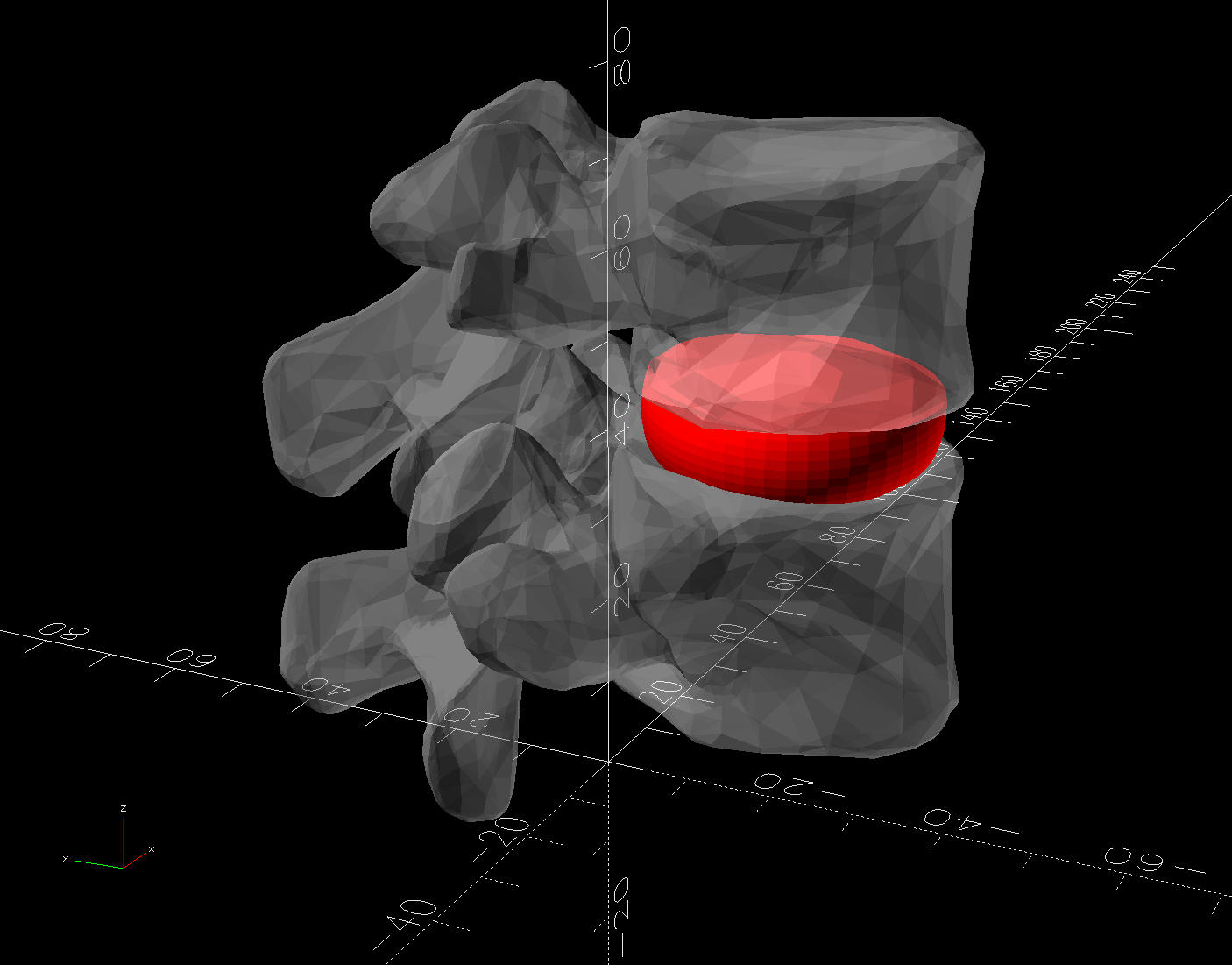
The OpenSCAD code doing the heavy lifting:
// Disk between L4 and L5 vertebrae
// Ed Nisley - KE4ZNU
// 2025-03-07

Layout = "Show";    // [Show,Build]

include <BOSL2/std.scad>

module Disk() {
  color("Red")
    difference() {
      translate([9,-18,36])
        rotate(110)
        resize([33,45])
        cyl(d=50,h=14,$fn=48,rounding=7,anchor=BOTTOM);
      import("../Spine/human-spinal-column-including-cervical-thoracic-and-lumbar-vertebra-model_files/L4 L5 vertebrae stacked.stl",
        convexity=10);
    }
}

if (Layout == "Show") {
  Disk();

  color("White",0.3)
      import("../Spine/human-spinal-column-including-cervical-thoracic-and-lumbar-vertebra-model_files/L4 L5 vertebrae stacked.stl",
        convexity=10);

}

if (Layout == "Build") {
  Disk();

}
All of the magic numbers come from eyeballometric measurement & successive approximation.
The Build layout left the disk floating in space, whereupon I used PrusaSlicer to reorient it edge-downward on the platform with painted-on support for minimal distortion:
Two dots of E6000+ adhesive hold everything together.
All in all, it was a useful distraction. I’ve been vertically polarized for the last five days and it’s good to be … back.
Having devoted considerable effort to smoothing the HQ Sixteen’s path across the table, with commensurate improvement, Mary reported the machine suddenly developed a severe hitch in its left-to-right git-along. Given that she is moving fifty pounds of machine with fingertip pressure, anything interrupting its progress is a problem.
We found a spot where the machine abruptly and repeatably stopped rolling, but none of the four wheels had a visible problem and both tracks were smooth. The stitch regulator wheel sat directly above a table surface joint on the track base, but lifting it didn’t change the glitch. Rolling the machine while lifting the rear wheels off the track, which is significantly more difficult than it may seem, still encountered the bump.
Rolling while lifting the front wheels went smoothly, so something was wrong with one of the front wheels. I put the machine back at the worst spot, marked the bottom of both wheel rims, lifted-and-rotated the left wheel half a turn, and found the glitch happened with the right wheel’s mark downward.
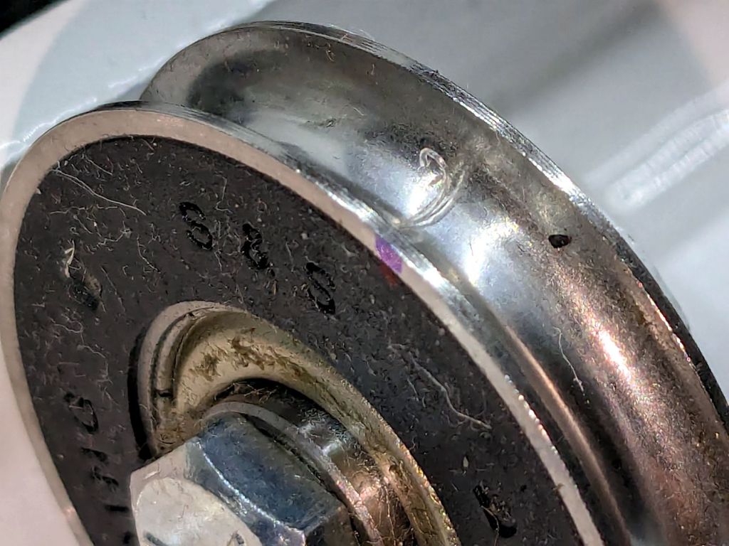
I lifted the machine off the carriage, took the carriage to the Basement Shop, and discovered what we could not see in situ:
For scale, the wheels are 8 mm across the flanges.
That thing looks like this up close:
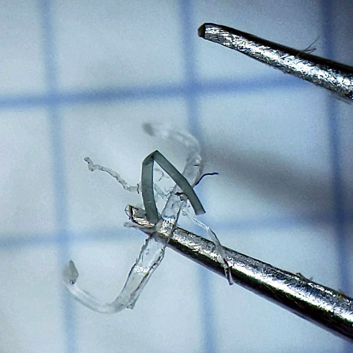
The fibers were almost invisible in my palm as I carried it upstairs to show it off.
Apparently, a few millimeters of plastic fiber dropped from space directly onto the track and got mashed into the wheel as it rolled along. Given the vast expanses of fabric & batting going into projects on a long-arm sewing machine, that crud could have come from anywhere.
As we now realize just how much trouble can come from a tiny bit of crud, finding the next hitch in the git-along will be easier.
