The Smell of Molten Projects in the Morning

Ed Nisley's Blog: Shop notes, electronics, firmware, machinery, 3D printing, laser cuttery, and curiosities. Contents: 100% human thinking, 0% AI slop.

Author: Ed

  • Panasonic Eneloop Pro NiMH Cells: First Charge

    The Sony DSC-H5 expects a much higher voltage from its pair of NiMH AA cells than the tired Sanyo Eneloops from 2010 can provide these days.

    Eneloop - 8-cell pack - 2010 - 2016 - merged
    Eneloop – 8-cell pack – 2010 – 2016 – merged

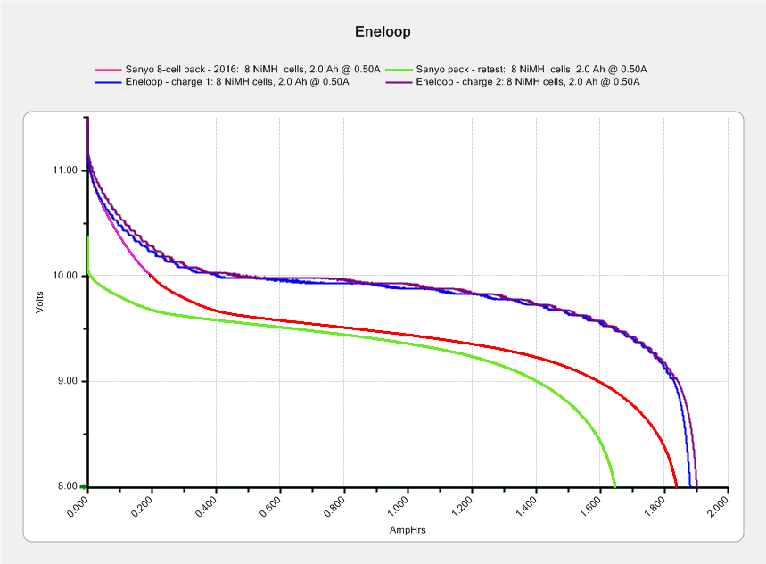
    The two upper curves show the first two charges for those eight cells back in 2010.

    The lower curve(s) started out with the wrong endpoint voltage (purple part of the middle curve), so I restarted the test (green curve) and edited the graph image to splice the two curves together into the purple/red curve.

    Although the capacity measured in mA·h isn’t much lower, the voltage depression reduces the available energy and trips the “low battery” alarm much earlier. In round numbers, the old cells were good for a few pictures, even hot off the charger, and didn’t have much energy left without being recharged before use.

    A quartet of Panasonic Eneloop Pro cells just arrived from BatterySpace, a nominally reputable supplier, all sporting a 14-05 date code suggesting they’re just shy of two years old. The packaging claims 85% charge retention after a year, so they should have a bit more than half of their rated 2.45 A·h “minimum” (or 2.55 mA·h “typical”, depending on whether you trust the label on the cell or the big print on the package) capacity remaining (although we don’t know the original state of charge, done from “solar power”). The lower curves say they arrived with 1 A·h remaining:

    Panasonic Eneloop - First Charge
    Panasonic Eneloop – First Charge

    However, the terminal voltage on those bottom curves would have any reasonable device reporting them as dead flat almost instantly, so you really can’t store Eneloops for two years: no surprise there.

    One pass through the 400 mA Sony charger produced the upper curves, with the dotted red curve from Cell A lagging in the middle. After that test, another pass through the charger brought Cell A back (upper solid red line) with the others, so I’ll assume it took a while to wake up.

    A pair of these in the camera will produce 2.2 V through 2.2 A·h, far better than the aged-out Sanyo Eneloops.

    Charging them at 400 mA = C/6 certainly counts as a slow charge. I’ve been charging the Sanyo cells in slow chargers in the hope that they’ll remain happier over the long term.

    The Panasonic Eneloops perform much better than some other cells you’ve seen around here, which may be due to the fact that I paid $5 each for them…


  • Sony NP-FS11 Lithium Battery Rebuilds: 2016

    It seems that two years is about as long as the NP-FS11 batteries last, as shown by the two lower curves from the ones I rebuilt in December 2013 with cells from 2011:

    Sony NP-FS11 2011-2016 Packs
    Sony NP-FS11 2011-2016 Packs

    The two middle curves with those same colors show the “back then” performance of those batteries: they’re shot in both total capacity and terminal voltage.

    I bought enough cells back in 2011 to leave two cells unused until now, which I built into a pack and charged. The green curve in the middle shows the result: those cells haven’t lost anything over the last five (!) years, as their performance still matches the other two batteries when they were new.

    The red curves come from a pair of batteries made with fresh new cells from batteryspace.com. They’re nominally 650 mA·h cells, so the NP-FS11 configuration (two parallel cells) should produce 1300 mA·h; surprisingly, they show 1500 mA·h with a nice voltage curve.

    So, although the 2011 cells work as well as their (now defunct) siblings, that pack can’t deliver the same capacity as the new cells. I expect I’ll rebuild it with 2016 cells in about a year.

    For whatever it’s worth, rebuilding these batteries goes much faster when I don’t have to saw them open. The Kapton tape wrapped around the case halves secures them well enough; there’s no need for fancy gluing.

    NP-FS11 Battery Rebuilds - 2016-03
    NP-FS11 Battery Rebuilds – 2016-03

    Yeah, I should make better labels. It’s hard to form a deep emotional attachment to the poor things, though.

    Here’s a case where something performs better than expected; I don’t always buy cheap junk from the usual eBay vendor…


  • Raspberry Pi Model 2: Canakit Case Reset Button Mod

    Being a Linux box, a Raspberry Pi requires a tidy shutdown, but, because it uses so little power after that, I decided to forego a power switch and just blip the CPU reset line to start it up again. Canakit cases require a bit of flush-cutter hackage to accommodate a crude socket atop the RUN header:

    Canakit RPi Case - reset switch - header clearance
    Canakit RPi Case – reset switch – header clearance

    The switch originally had three terminals, but turned out to be SPST NO with one unused pin. Flush cutters and some hot melt glue to the rescue:

    Canakit RPi Case - reset switch - interior
    Canakit RPi Case – reset switch – interior

    The end result looks OK, modulo a few scuffs on the shiny black plastic:

    Canakit RPi Case - reset switch - exterior
    Canakit RPi Case – reset switch – exterior

    Yeah, a clumsy swipe could wipe that actuator right off the top; we’ll see how long it lasts…

  • OttLite LED Conversion

    Although Mary liked the illumination from her OttLite (an old 13 W fluorescent Folding Task Lamp), neither of us liked its tiny base and tippy nature. It recently fell / was dropped / jumped to its doom, smashing the CFL tube and wreaking havoc on the tiny plastic studs holding its large cast-iron weight and steel base in position. Given that the CFL ballast had started humming a while ago, I took it apart to see whether I could salvage anything from the rubble.

    Remove:

    • Four screws under the fuzzy felt feet
    • One screw under the label on the back
    • A final screw that becomes visible only after disemboweling the hinge assembly by unscrewing the obvious endcaps:
    OttLite LED Conversion - hinge screw
    OttLite LED Conversion – hinge screw

    Pull the hinge end of the white inside panel away from the outer stand at enough of an angle to disengage all three latches holding it to the base, then remove it just enough to let you start cutting wires around the ballast…

    I rebuilt the thing with a pair of 24 V 150 mA warm-white LED panels (good industrial surplus, not the usual cheap eBay crap) powered by a 19 V laptop adapter (from IBM, no less) through a (cheap eBay) boost converter sticky-foam-taped where the fluorescent ballast used to live:

    OttLite LED Conversion - boost supply wiring
    OttLite LED Conversion – boost supply wiring

    The power supply had only two conductors, the central wire surrounded by twisted shielding, and didn’t require a fussy interface. Hooray for simple bulk power supplies; I lopped off the connector and soldered the wires directly to the boost converter.

    The original lamp wiring has a 120 VAC switch inside the hinge that turned the lamp on as you raise the arm holding the CFL tube: exactly what I need for its new use. That eliminated figuring out how to crack the arm apart to rewire it.

    I harvested the base from a(nother) defunct CFL bulb:

    OttLite LED Conversion - harvested CFL base
    OttLite LED Conversion – harvested CFL base

    By soldering wires directly into the pins, I could reuse the existing CFL socket in the lamp arm, the existing wiring, and the switch.

    The LED panels dissipate 3-ish W each:

    OttLite LED Conversion - LED panel layout
    OttLite LED Conversion – LED panel layout

    They’re mounted on a 0.1 inch aluminum sheet from the heap that required exactly one saw cut to fit into the space available, so I defined it to be perfect. The 4-40 screws holding the panels in place continue through the plate and 3/8 inch aluminum standoffs into a quartet of knurled inserts epoxied into eyeballometrically match-drilled holes in the lamp arm:

    OttLite LED Conversion - epoxied threaded inserts
    OttLite LED Conversion – epoxied threaded inserts

    The faint yellowish discoloration from the CFL tube’s heat and UV is much more visible in real life, but nobody will ever see it again. The scrawled blue (+) and (-) marks give the socket polarity; it’s not mechanically polarized and a bit of care is in order. The black rectangle is actually a shiny metal sheet intended to reflect heat from the CFL tube’s base away from the plastic arm.

    I set the boost converter to 23.5 V, at which point the LED panels draw about 100 mA each and get just over uncomfortably warm after an hour or two:

    OttLite LED Conversion - in action
    OttLite LED Conversion – in action

    The panels run 120 °F = 50 °C and the SMD LEDs probably exceed 150 °F = 65 °C. The scant surplus doc touted “No heatsink required” and the single-sided FR4 PCB insulates the LEDs from the aluminum sheet, but I still smeared some heatsink compound behind the panels in the hopes of spreading the heat out a bit.

    I glued the shattered base studs back in place with IPS #3, surrounded them with generous epoxy fillets, plunked the cast iron weight in place atop some waxed paper to mold the epoxy to fit (and let me remove it again, if needs be), screwed everything together, and stuck a foam sheet over the steel base plate. It’s as tippy as before, but at least the LEDs won’t shatter if when it falls. It really needs a larger base; a polycarbonate plate might work, if only I could figure out how to attach it.

    All in all, the lamp looks good and the warm-white LEDs with DC drive don’t produce that horrible fluorescent flicker.

    The lamp now sports a label identifying it as a NisLite; because P-Touch labeler.

  • Tour Easy: Long-Deferred Drivetrain Maintenance

    A few months back, the 13-tooth sprocket on my Tour Easy started skipping, which reminded me that I planned to replace all the drivetrain components. Time passed, the winter remained unseasonably warm and sunny, we kept riding, the skipping got much worse, and I just shifted across that sprocket.

    Finally, the rains returned, I heaved the bike up on the workstand, and started replacing things. Judging from the accumulated crud and severe wear, it’s been on there for quite a while:

    Sprocket with broken teeth - as found
    Sprocket with broken teeth – as found

    Here’s the offending 13-tooth sprocket, all shined up;

    Sprocket with broken teeth - detail
    Sprocket with broken teeth – detail

    I don’t recall a catastrophic failure that stripped all those teeth off in one shot. A closer look showed cracks in the few remaining teeth:

    Sprocket with broken teeth - cracked teeth
    Sprocket with broken teeth – cracked teeth

    Which explains why the skipping gradually got worse: the poor sprocket shed teeth as I rode blithely along.

    Huh.

    That’s what happens with a severely worn sprocket: the chain applies tension to just the topmost tooth, rather than distributing it on the teeth around a third (or more) of the sprocket, and, one by one, that force breaks the teeth. The top picture shows at least one other sprocket with a missing tooth; all display the shark-fin profile of heavy wear.

    As you can tell from the other bike pix & repairs around here, I’d rather ride than mess around with cleaning and suchlike. We’re on our second set of drivetrain components in 15 years, so I’d say treating all that stuff as consumable seems a fair tradeoff…

  • Monthly Image: Red Oaks Mill Dam

    Heavy rain during an unseasonably warm spell rearranged the deadwood over the Red Oaks Mill Dam:

    Red Oaks Mill Dam - 2016-03-04
    Red Oaks Mill Dam – 2016-03-04

    Much of the wood collects around the pool on the other side of the bridge where the Mighty Wappingers Creek makes a right-angle turn to the left and continues toward the Hudson.

    After the rain, the weather became much colder (which was OK, as I didn’t have to shovel the rain off the driveway), and the spray froze on the deadwood:

    Red Oaks Mill Dam - icicles on deadwood
    Red Oaks Mill Dam – icicles on deadwood

    A few weeks ago, we walked by the dam at the right moment to catch the sun highlighting the rubble upstream of the decaying dam breast:

    Red Oaks Mill Dam - dam breast upstream rubble
    Red Oaks Mill Dam – dam breast upstream rubble

    There won’t be much left in a few more decades …

  • Knurled Inserts: Epoxy Anchoring

    After taking the incandescent lamp socket off its base, I drilled the tapped (yeah, in plastic) 6-32 holes out to a firm press fit for the knurled 6-32 inserts, buttered the inserts with epoxy, and pressed them firmly in place:

    Lamp Base - epoxy knurled insert
    Lamp Base – epoxy knurled insert

    Fast forward a day and they’re stuck in there like they were glued. You can see a bit of the epoxy around the right rim of the insert; I wiped a bit more off around the other one.

    Putting The Right Amount of epoxy on the insert requires dialing back my “The bigger the blob, the better the job” enthusiasm, but wasn’t all that difficult. It’s certainly more tedious than just ramming the inserts into a printed hole and might actually produce better retention. I doubt that will make the least difference for (almost) anything I build.

    On the whole, they look good…