The Smell of Molten Projects in the Morning

Ed Nisley's Blog: Shop notes, electronics, firmware, machinery, 3D printing, laser cuttery, and curiosities. Contents: 100% human thinking, 0% AI slop.

Author: Ed

  • Miniblind Cord Caps

    After smashing one of the cord pulls between the sash and the frame:

    Miniblind cord caps - installed
    Miniblind cord caps – installed

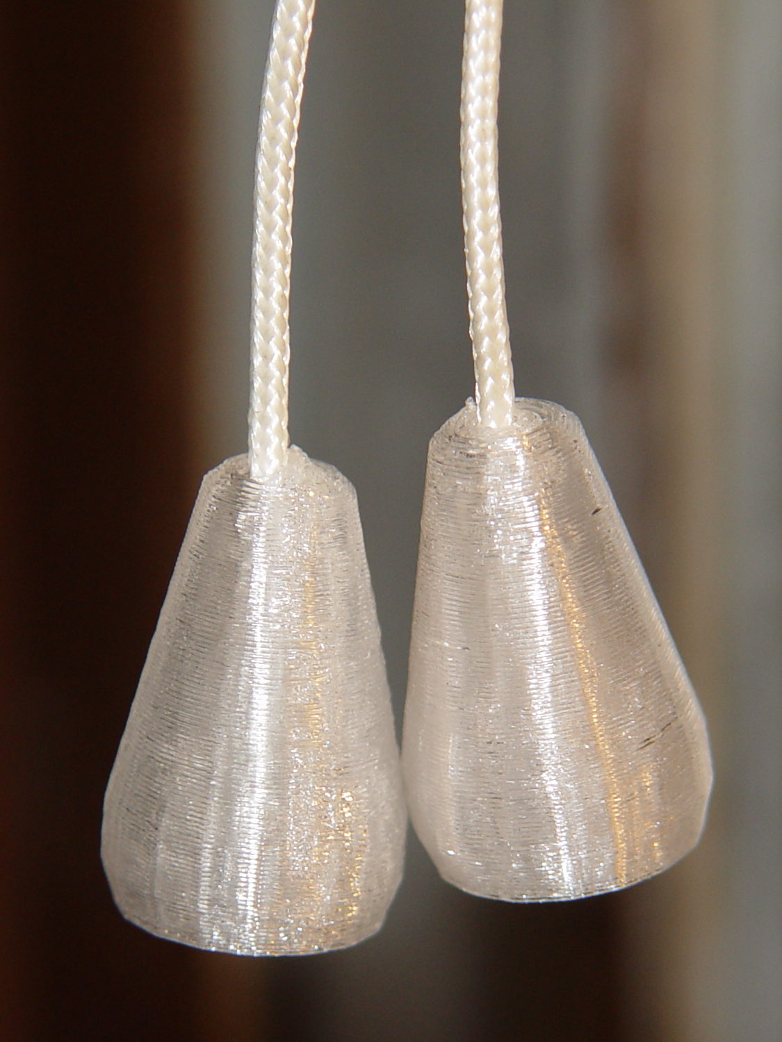
    The glittery PETG looks surprisingly good in the sunlight that will eventually change it into dullness. The black flecks come from optical effects in the plastic, not the usual burned PETG snot.

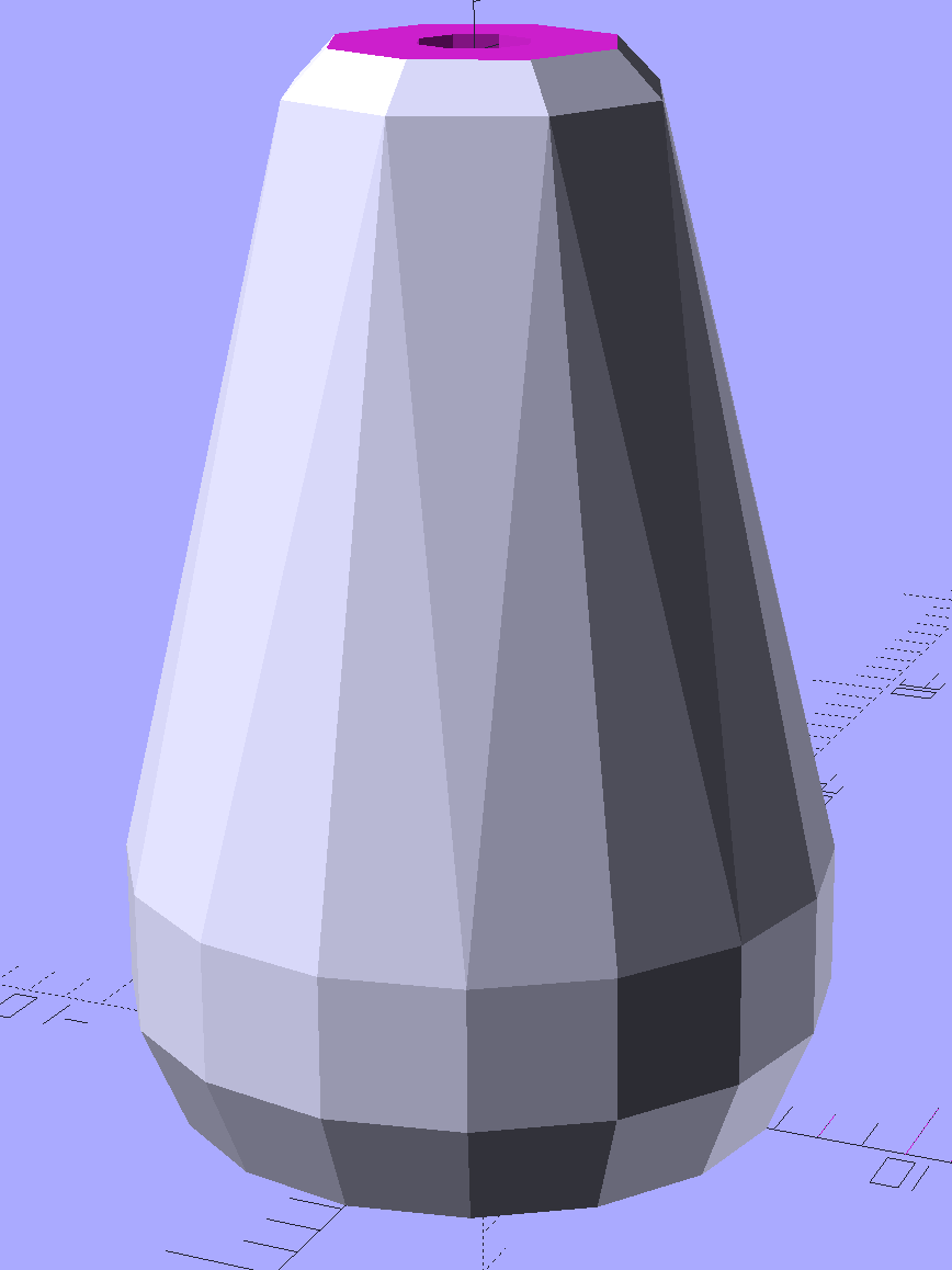
    The solid model is basically a hull around two “spheres”, truncated on top & bottom:

    Miniblind cord cap - solid model
    Miniblind cord cap – solid model

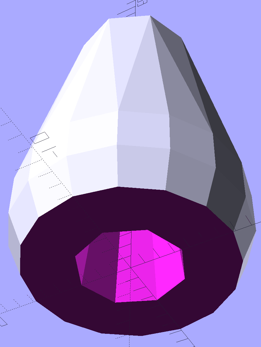
    The interior has a taper to accommodate the knot, but they’re chunky little gadgets:

    Miniblind cord cap - solid model - bottom
    Miniblind cord cap – solid model – bottom

    I thought the facets came out nicely, even if they’re mostly invisible in the picture.

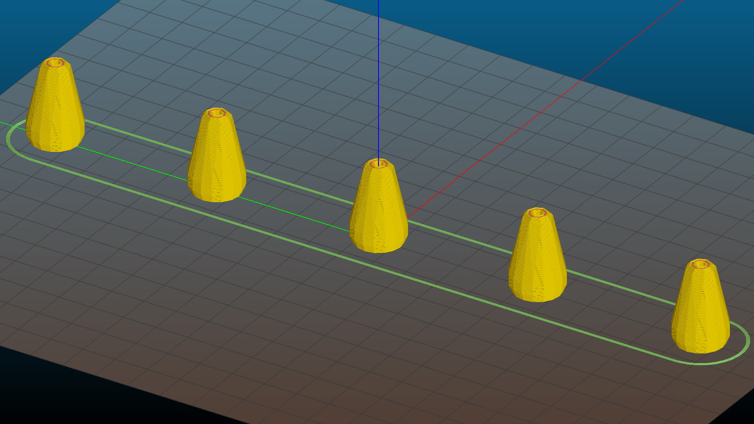
    Each pull should build separately to improve the surface finish, so I arranged five copies in sequence from front to back:

    Miniblind cord cap - 5 sequential - Slic3r preview
    Miniblind cord cap – 5 sequential – Slic3r preview

    If you’re using an M2, the fans hanging off the front of the filament drive housing might come a bit too close for comfort, so rotate ’em upward and out of the way.

    If you remove the interior features and flip ’em upside down, they’d work well in Spiral Vase mode. You’d have to manually drill the top hole, though, because a hole through the model produces two shells.

    The OpenSCAD source code as a GitHub Gist:

    // Cap for miniblind cord
    // Ed Nisley KE4ZNU – August 2016
    //– Extrusion parameters – must match reality!
    ThreadThick = 0.25;
    ThreadWidth = 0.40;
    Protrusion = 0.1;
    HoleWindage = 0.2;
    //——
    // Dimensions
    OD1 = 0;
    OD2 = 1;
    LENGTH = 2;
    Cap = [9.0,16.0,25.0];
    Cord = [2.5,7.0,Cap[LENGTH] 5];
    NumSides = 8;
    //———————-
    //– Build it
    difference() {
    hull() { // overall shape
    translate([0,0,Cap[LENGTH] Cap[OD1]/2])
    sphere(d=Cap[OD1],$fn=NumSides);
    translate([0,0,0.5*Cap[OD2]/2])
    sphere(d=Cap[OD2],$fn=2*NumSides); // round the bottom just a bit
    }
    translate([0,0,Cap[LENGTH]/2]) // trim bottom
    cube([2*Cap[OD2],2*Cap[OD2],Cap[LENGTH]],center=true);
    translate([0,0,Cap[LENGTH] + 0.8*Cap[OD1]]) // trim top (arbitrarily)
    cube([2*Cap[OD1],2*Cap[OD1],2*Cap[OD1]],center=true);
    translate([0,0,Protrusion])
    cylinder(d=Cord[OD1],h=(Cap[LENGTH] + 2*Protrusion),$fn=NumSides);
    translate([0,0,Protrusion])
    cylinder(d1=Cord[OD2],d2=Cord[OD1],h=(Cord[LENGTH] + Protrusion),$fn=NumSides);
    }
  • Counterfeit FTDI USB-Serial Adapter Roundup

    As part of the vacuum tube lighting project, I picked up a bunch of USB-Serial adapters, with the intent of simply building them into the lamp base along with a knockoff Arduino Pro Mini, then plugging in a cheap USB wall wart for power. An Arduino Nano might make more sense, but this lets me use the Pro Minis for other projects where power comes from elsewhere.

    Anyhow, I deliberately paid a few bucks extra for “genuine” FTDI chips, knowing full well what was about to happen:

    Assorted FT232 Converters
    Assorted FT232 Converters

    The two boards on the bottom have been in my collection forever and seem to be genuine FTDI; the one on the left came from Sparkfun:

    FT232RL - genuine
    FT232RL – genuine

    The top six have counterfeit chips, although you’d be hard-pressed to tell from the laser etching:

    FT232RL - fake
    FT232RL – fake

    In addition to the boards, I picked up the blue square-ish cable adapters for the HP 7475A plotter project and, again, paid extra for “genuine” FTDI chips. The other adapters, based on Prolific PL2303 chips, I’ve had basically forever:

    Assorted FT232 Converters - Cabled
    Assorted FT232 Converters – Cabled

    Those two have chips with different serial numbers: genuine FTDI chips get different serial numbers programmed during production. The counterfeits, well, they’re all pretty much the same.

    Display the serial numbers thusly:

    lsusb
    Bus 002 Device 024: ID 0403:6001 Future Technology Devices International, Ltd FT232 Serial (UART) IC
    ... snippage ...
    udevadm info --query=all --attribute-walk  --name=/dev/bus/usb/002/024 | grep ser
        ATTR{serial}=="A6005qSB"
    

    All the counterfeit FTDI chips report the same serial number: A50285BI. The PL2303 chips don’t report serial numbers.

    For my simple needs, they all work fine, but apparently fancier new microcontrollers expect more from their adapters and the counterfeits just can’t live up to their promises.

    For a while, FTDI released Windows drivers that bricked counterfeit chips; the Linux drivers were unaffected.

  • Monthly Science: Sony NP-BX1 Battery Status

    Having had the weaker of the two surviving STK batteries die 36 minutes into a ride, I tested them all:

    Sony NP-BX1 - 1 A test - 2016-08-17
    Sony NP-BX1 – 1 A test – 2016-08-17

    The X axis shows W·h, rather than the usual A·h, because that seems more useful in a world of constant-power supplies.

    The test current is now 1 A, rather than the previous 500 mA, to more closely match the camera’s actual load. The CBA tester doesn’t have a constant-power mode; I think that doesn’t make much practical difference.

    The orange curve (STK D) is the failed battery, ending after 1.4 W·h. At an average 3.2-ish V, that’s 26 minutes, which is close enough to the actual run time, given the different current.

    The red curve (STK C) is the sole STK battery of the original four from last November that actually worked.

    The upper two curves come from the mostly unused Wasabi batteries (F and G), also from November. They have lost a bit of their capacity, but show the highest voltage out toward the end, so that’s good.

    The black curve is the lightly used Sony OEM battery that came with the camera. Although it has about the same ultimate capacity as the other three “good” batteries, the voltage depression suggests it’ll trip out early.

    The others are pretty much debris by now. I suppose they might be good for LED blinkies or some other low-voltage and low-current application, but …

    So I’ll start using all four of the better batteries and see how the run times work out in actual use.

  • ITead Studio Quasi-Colorduino RGB LED Matrix Shield: Redesign Doodles

    Some notes on a recent acquisition that ought to allow random dots with individual brightness control (unlike my simple resistor-limited hack job):

    Color Shield - DM163 M54565 - demo
    Color Shield – DM163 M54565 – demo

    A Colorduino is a dedicated board that combines an Arduino-class microcontroller with hardware drivers for an 8×8 RGB LED matrix, with daisy-chaining I/O to build bigger displays. The Colors Shield you see above omits the Arduino circuitry and daisy-chaining hardware: it plugs atop an ordinary Arduino UNO-class board as a dedicated 8×8 tile driver.

    I do not profess to understand the ancestry & family tree of those designs and their various incarnations. This schematic doesn’t match the knockoff hardware in hand, which isn’t surprising after half a dozen years of relentless product cheapnification:

    ITeadStudio - RGB LED shield - DM163 M54564 - SPI notes
    ITeadStudio – RGB LED shield – DM163 M54564 – SPI notes

    It comes close enough for a big-picture overview…

    The DM163 has 8×3 constant current sink PWM pins that connect to the column cathodes of the RGB matrix. It provides either 8 or 6 bits of PWM control for each output, with either 6 or 8 bits of gamma correction to make the grayscale shades work out properly (those are separate shift registers and the PWM generators use both, so the chip doesn’t care how you divvy up the 14 bits).

    The three 1 kΩ resistors set the current to 60 mA per output pin. The LED matrix might support anywhere from  70 to 120 mA peak current per LED, but I doubt the supplied matrix matches any of the available datasheets. The total current depends on the number of LEDs lit on each row, so large dark areas are a Good Thing.

    The serial protocol looks enough like SPI to get by, with controls for Reset, Latch, and Bank Select.

    The board has no power supply other than the single Arduino VCC pin, so you’re looking at a peak of 24 x 60 mA = 1.44 A through that pin. The Arduino regulator must supply that load pretty much full-time, which is obviously a Bad Thing; plan on plenty of dark areas.

    The DM163 SPI connections don’t use the Arduino’s hardware SPI, so it’s full-frontal bit-banging all the way. Three DM163 control bits use a trio of analog inputs as digital outputs. No harm in that, works fine with the knockoff Neopixels.

    The M54564 is a PNP high-side driver converting logic-level inputs to the current required for the row anodes of the matrix. The eight input bits are non-contiguous across the Arduino’s digital outputs. You could turn on all the M54564 outputs at once, which would be a Bad Thing.

    You shift 24 bytes of RGB data into the DM163 and latch the data, then raise one of the M54564 inputs to enable a given row of LEDs, which light up with the corresponding colors.

    The bit-banged SPI runs at 1.9 µs/bit and sending all 24 bits to the DM163 requires 450 µs. With a 100 Hz refresh, that’s a mere 5% overhead, but the fact that the board soaks up essentially all the I/O pins means the Arduino isn’t not doing much else in the way of real-world interaction.

    The Arduino driver, of dubious provenance, sets Timer 0 for 100-ish Hz interrupts. Each interrupt shifts another batch of bytes into the DM163 and selects the appropriate row. The driver uses a double-buffered array that soaks up 2x8x8x3 = 384 bytes of precious RAM, in addition to a bunch of working storage.

    If I were (re)designing this board…

    A separate power input jack for the DM163 that might optionally feed the Arduino’s VIN raw power pin.

    Use the Arduino SPI hardware, dammit.

    Put an HC595 shift register behind the M54564, so you’d shift 24 + 8 = 32 bits into the board, then strobe the latches. That eliminates eight digital pins used as a parallel port.

    You’d surely want to disable the row driver while switching the column drivers to avoid ghosting, so figure on a separate output enable for the HC595. That tri-states the 595’s outputs; although the M54564 has internal pulldowns, it might need more.

    It’s entirely usable as-is, but sheesh it’d be so easy to do a better job. That wouldn’t be software compatible with all the Arduino Love for the existing boards out there; there’s no point.


  • Epson R380 Printer: Resetting the Waste Ink Counter Again

    The Epson R380 printer never gets turned off, so it rarely has a chance to complain. After a powerdown due to refreshing the UPS batteries, it lit up with the dreaded “Service required. Visit your friendly Epson repair center” message that indicates you should just throw the printer out, because replacing the internal ink absorber mats / draining the internal tank is, mmm, economically infeasible when you pay somebody else to do it.

    Having done this before, though, it’s almost easy…

    • Pop a PC with a Windows partition off the to-be-recycled stack
    • Boot System Rescue CD
    • Back up the partition to a junk hard drive, just for practice
    • Copy the subdirectory of sketchy utilities to the Windows drive
    • Boot Windows (with no network connection)
    • Run sketchy utility to reset the ink counter
    • Boot SRC, restore partition
    • Return hard drive & PC to their respective piles
    • Declare victory and move on

    This time, a sketchy utility that resembled the Official Epson Reset Program actually reset something and the printer started up normally. As before, however, the saved MBR didn’t match the on-disk MBR, suggesting that either I don’t understand how to save / restore the MBR or that something once again meddled with the MBR in between the backup and the restore.

    I’ve emptied the waste ink tank maybe three times since the last reset: plenty of ink down the drain. Fortunately, I loves me some good continuous-flow ink supply action…

    Sheesh & similar remarks.

  • Switch Contact Bounce

    An Arduino hairball for an upcoming Digital Machinist column:

    Arduino UNO clone - test setup
    Arduino UNO clone – test setup

    A short program monitors the switch. When it closes, the program reads the analog voltage from the pot and blinks the LED (on Pin 13, so you don’t need an external LED) for that number of milliseconds.

    Some diligent rummaging produced a spectacularly bouncy switch (lower trace) with the output pulse (upper trace):

    Contact Bounce - Matsuhita - NO 1
    Contact Bounce – Matsuhita – NO 1

    A longer timebase shows it’s rattling around for nearly half a millisecond:

    Contact Bounce - Matsuhita - NO 2
    Contact Bounce – Matsuhita – NO 2

    The second pulse in the upper trace shows that the code gets around the loop() fast enough to retrigger on the same button push, which is part of the lesson in the column

    A midrange timebase:

    Contact Bounce - Matsuhita - NO 3
    Contact Bounce – Matsuhita – NO 3

    You could surely get a few random numbers out of that noise, although the first few bounces seem surprisingly consistent.

  • High-availability, High-reliability Trash Can

    We spotted this upgrade on a recent trip to a Powerhouse Theater production:

    Vassar Old Main - High-availability Trash Can
    Vassar Old Main – High-availability Trash Can

    Compared with the older version, I’d say it’s a great improvement:

    Vassar Old Main - Broken Trash Can 1
    Vassar Old Main – Broken Trash Can 1

    Who says things never get better?