Ed Nisley's Blog: Shop notes, electronics, firmware, machinery, 3D printing, laser cuttery, and curiosities. Contents: 100% human thinking, 0% AI slop.
This appeared on The Mighty Thor’s phone during a Squidwrench meeting:
BofA Phishing
“To maintain a secure banking environment” seems diagnostic of a scam.
Discouragingly, some of our banks still send emails with clicky links using third-party mail servers, so checkonlineinfo.com doesn’t seem any more suspicious than, say, Schwab’s customercenter.net.
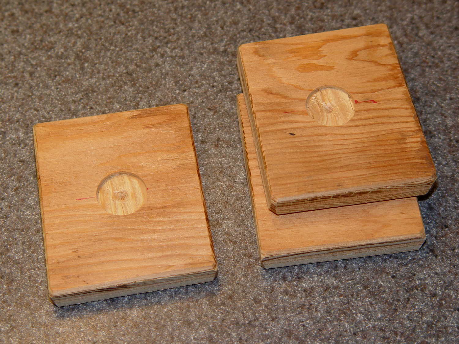
The slightly rectangular shape extracted four plates from of a scrap of 3/8 inch plywood, with almost nothing left over. The fourth plate had already found its way into the under-seat bag by the time I thought of a picture.
My can of fluorescent red paint having lost its mojo since the most recent application, these shall remain unpainted forever more; as even forget-me-not red seems to have little effect, that may not matter.
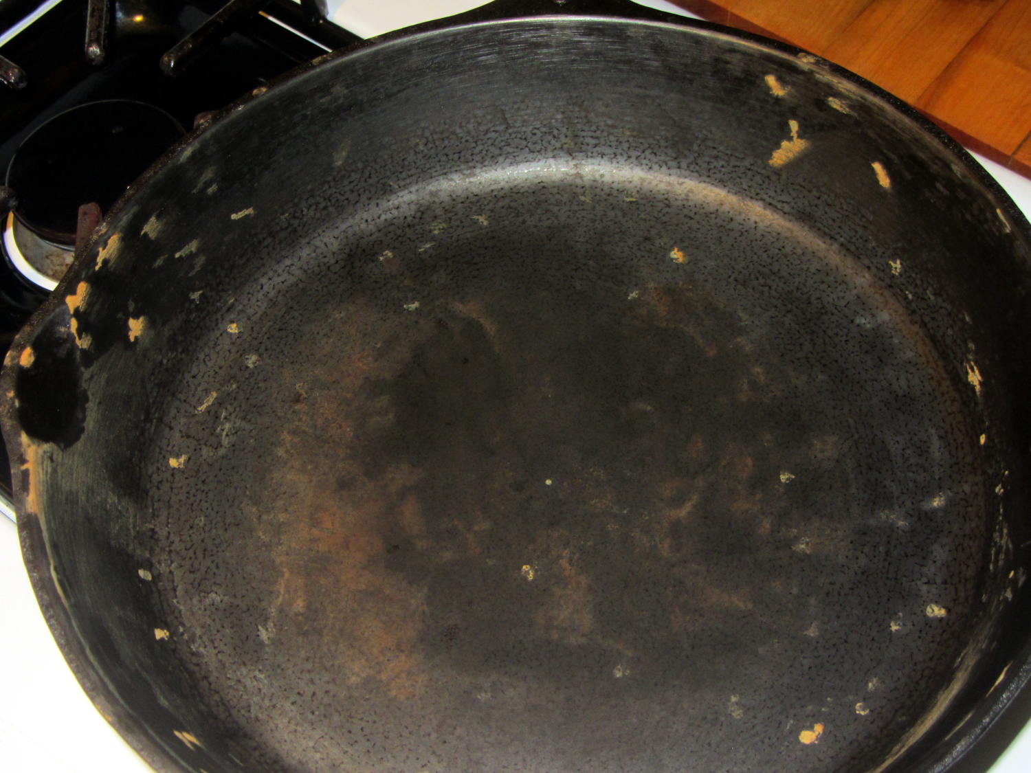
The original cast-iron seasoning recipe, after half a dozen iterations of flax seed oil & high-temperature baking, produced disappointing results:
Wagner cast iron skillet – washed – top
The key point of seasoning seems to require heating the oil enough to polymerize its molecular thingies, with (IMO) pretty nearly everything else boiling down to woo.
Since that rusting incident, I’ve done this after every use:
Wipe the pan clean with the same hot soapy water I use for everything else
Remove crud with the same Scotchbrite / sponge pad I use for everything else
Rinse and wipe dry with the sponge side of the pad
Set stove timer for 3 minutes
Put pan on simmer burner, set to high flame
Continue cleanup until timer sounds
Set stove timer for 3 minutes
Wipe half a dozen drops of flax seed oil around pan with cotton cloth scrap
Continue cleanup until timer sounds
Turn off simmer burner
Wipe pan with that oily cotton scrap
The pan reaches about 300 °F after 3 minutes. The “opening the pores” thing is woo, but a completely dry pan doesn’t spit back and that’s a major plus.
The pan tops out at a bit over 400 °F after a total of 6 minutes. There’s no smoke, no excitement, just a hot pan on the back burner.
Given that I’m washing the pan anyway, the whole “seasoning” operation adds maybe two minutes to the process. By now, it’s entirely automatic.
Nota Bene: Set the timer before turning on the burner and before adding the oil, because you will become distracted and will not remember the pan quietly heating on the back burner. You have been warned.
After two months of doing that about once a day:
Wagner Cast Iron Skillet – Low Woo Seasoning
Granted, it looks about the same as the previous results, but this uniform dull black coating repels water, doesn’t rust, loves oil, wipes clean without scouring, and the daily omelet doesn’t stick hardly at all. Obviously, the key difference is that I’ve polymerized a gazillion coats of oil, rather than half a dozen.
Although I have no idea whether I’m exposing us to lethal free radicals created by the polymerization process, I doubt anybody else knows anything on that subject with regard to their own seasoning technique, so we’re pretty much even. As with most such worries, It Doesn’t Matter.
Next, I’ll just wipe the pan and let it dry in the rack. That coating should eventually wear off, at least in the high-traffic areas; let’s see how little maintenance it requires.
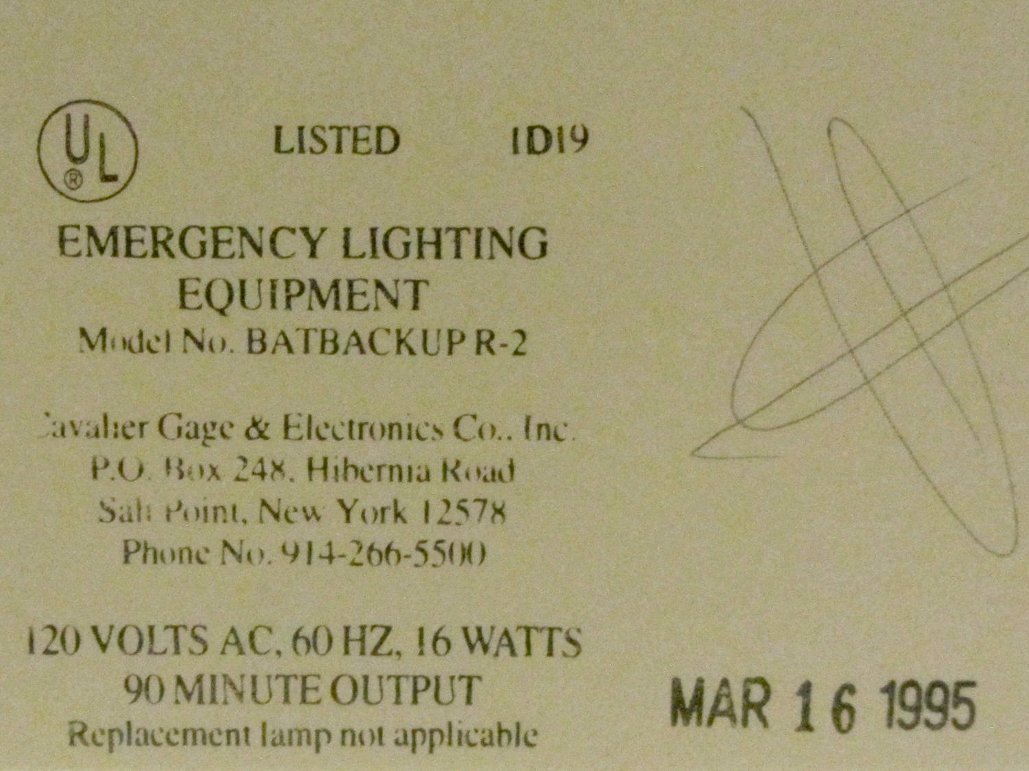
While at another Vassar concert, I noticed a manufacturing date stamp on one of the LED exit signs in Skinner Hall:
Exit Sign – Manufacturing date
I like the “Replacement lamp not applicable” line. I wonder how recently they’ve tested the battery for the projected 90 minutes of backup time…
These old LEDs show the expected brightness variations:
Exit Sign – LED aging
So, now you know what your discrete LEDs will look like after two decades of continuous use. That’s if anybody (else) still uses discrete LEDs, of course.
The mid-1950s wood doors on our house have wood storm doors with interchangeable wood-framed glass and screen panels. Twice a year, the diligent homeowner will swap the panels to match the season; during the last 60+ years, the glass panels remain undropped.
The back door has a diagonal tension brace to hold the door in shape; the door may be slightly distorted or the frame slightly out of square. In any event, the brace obstructs the panel, so the semiannual ritual includes loosening the brace and removing four screws. During the last 60+ years, the screw holes have required repair / filling several times; about five years ago, I plugged them with epoxy putty and drilled them to fit the screws.
That repair having aged out, I was about to renew the epoxy when I realized that I now have brass inserts that would work even better, if I replaced the original wood screws with 10-32 machine screws.
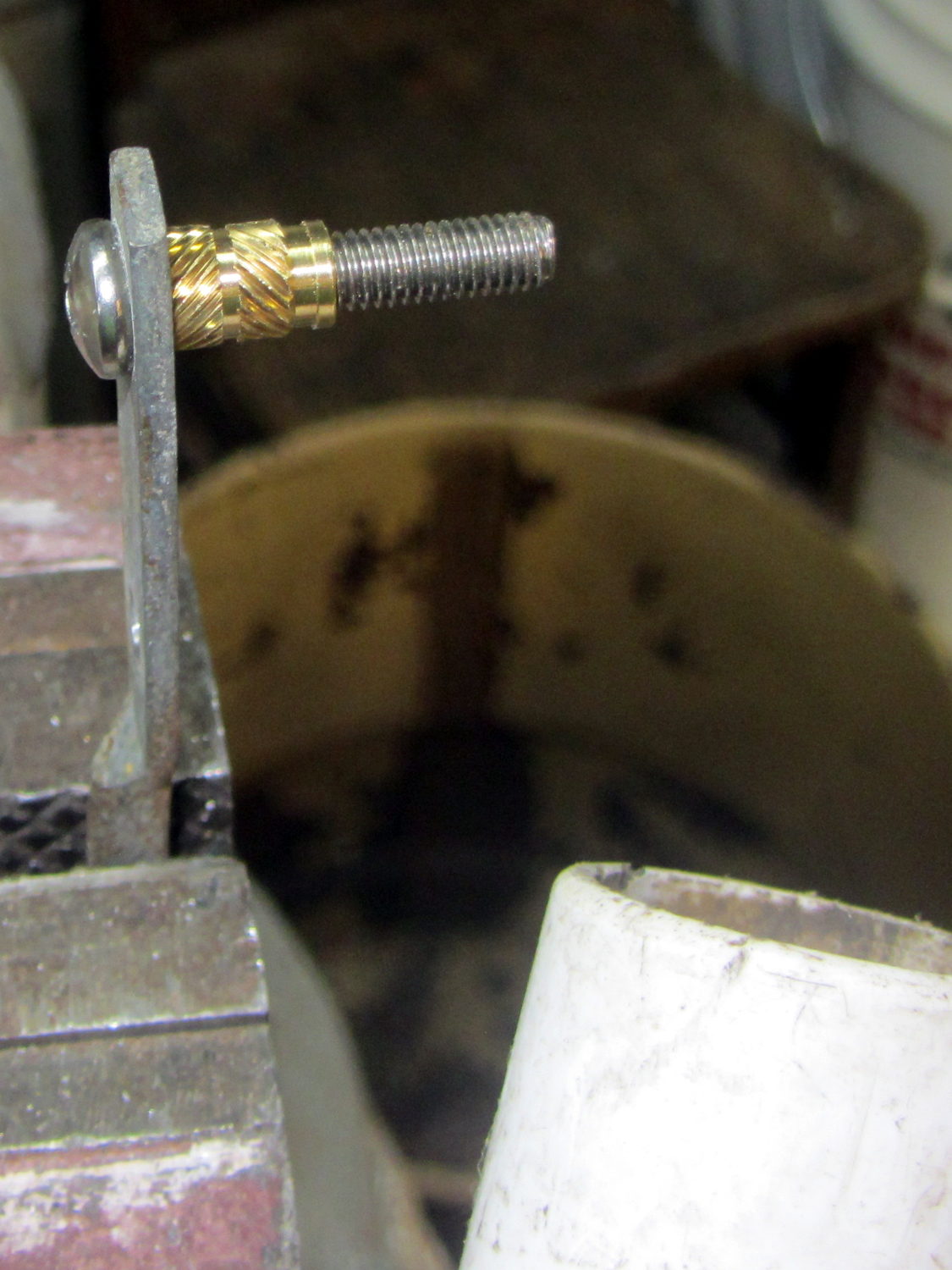
I cut the screws to the exact length using the brace and brass insert as a fixture:
Storm door – screw cutting
The vacuum cleaner nozzle to the lower right inhales the debris from the Dremel cutoff wheel that would otherwise fill the shop; I used up the last half of a wheel on four stainless steel screws.
Because each end of the brace has two screws, I knew that I couldn’t just drill out the four holes, plant four inserts, and be done with the job: the first insert on each end could go pretty nearly anywhere, but the second insert must match the brace hole spacing. The only way I know how to do that is to epoxy the first two inserts in place and let them cure, drill the other two holes slightly oversize, mount those inserts on the brace, butter them with epoxy, put the brace in place, tighten the first two screws, snug the brace, and hope I didn’t epoxy the brace to the door or the screws to the inserts.
Slips of waxed paper between the brace and the door prevented the first problem and oiling the screws prevented the second. It’s not the best-looking job I’ve ever done, but nobody will ever see the inserts behind the brace:
Storm door – inserts
Now, we’re ready for winter and I’m ready for spring!
Most likely, the new owners (whoever and whenever they may be) will never use these inserts, as they’ll replace all the windows & doors, plus sand & refinish the hardwood floors, before moving in …
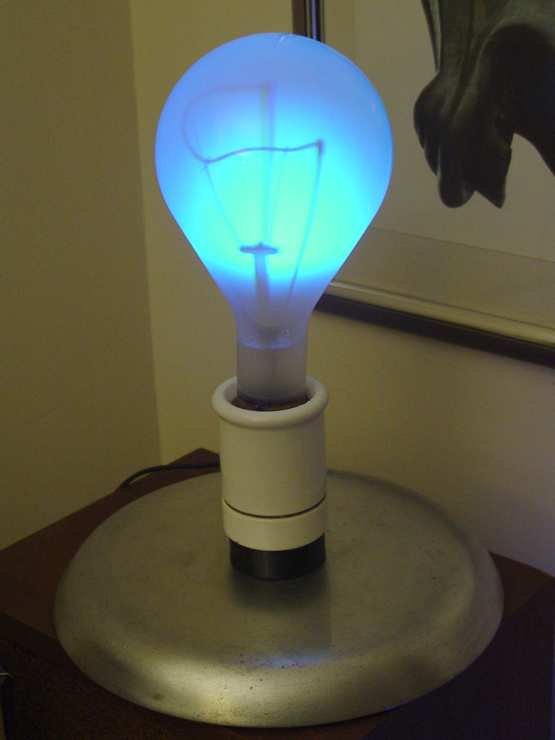
This obviously wasn’t ready for prime time, but it demonstrated feasibility with a socket on a base assembled for something else:
500 W Incandescent – backlit light
I recently salvaged a heavy aluminum lid that looked like a perfect complement for that bulb:
Mogul base – bulb – blue phase
The light comes from a rectangular knockoff Neopixel in a sidelight mount:
Mogul base – sidelight curing
That’s epoxied to the rear of the bulb, below the equator, where it casts the best-looking shadow of the filament and support structures on the inside of the bulb. Actually, it’s taped in place for a week’s worth of burn-in to see if it survives.
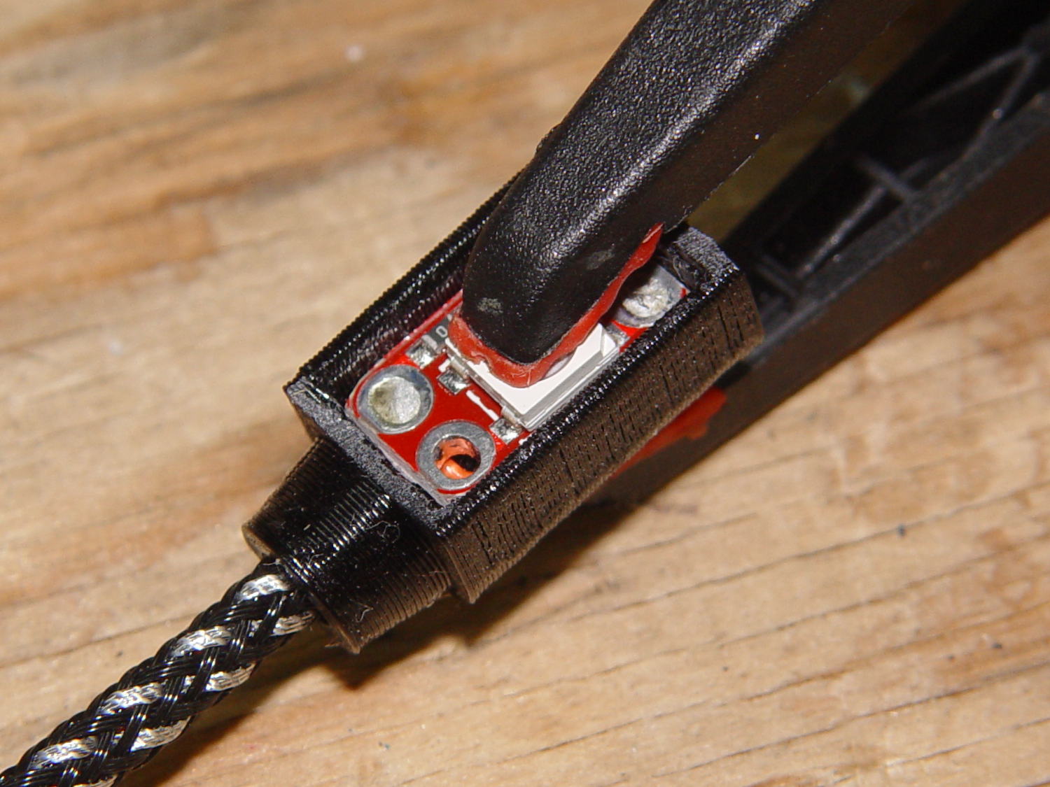
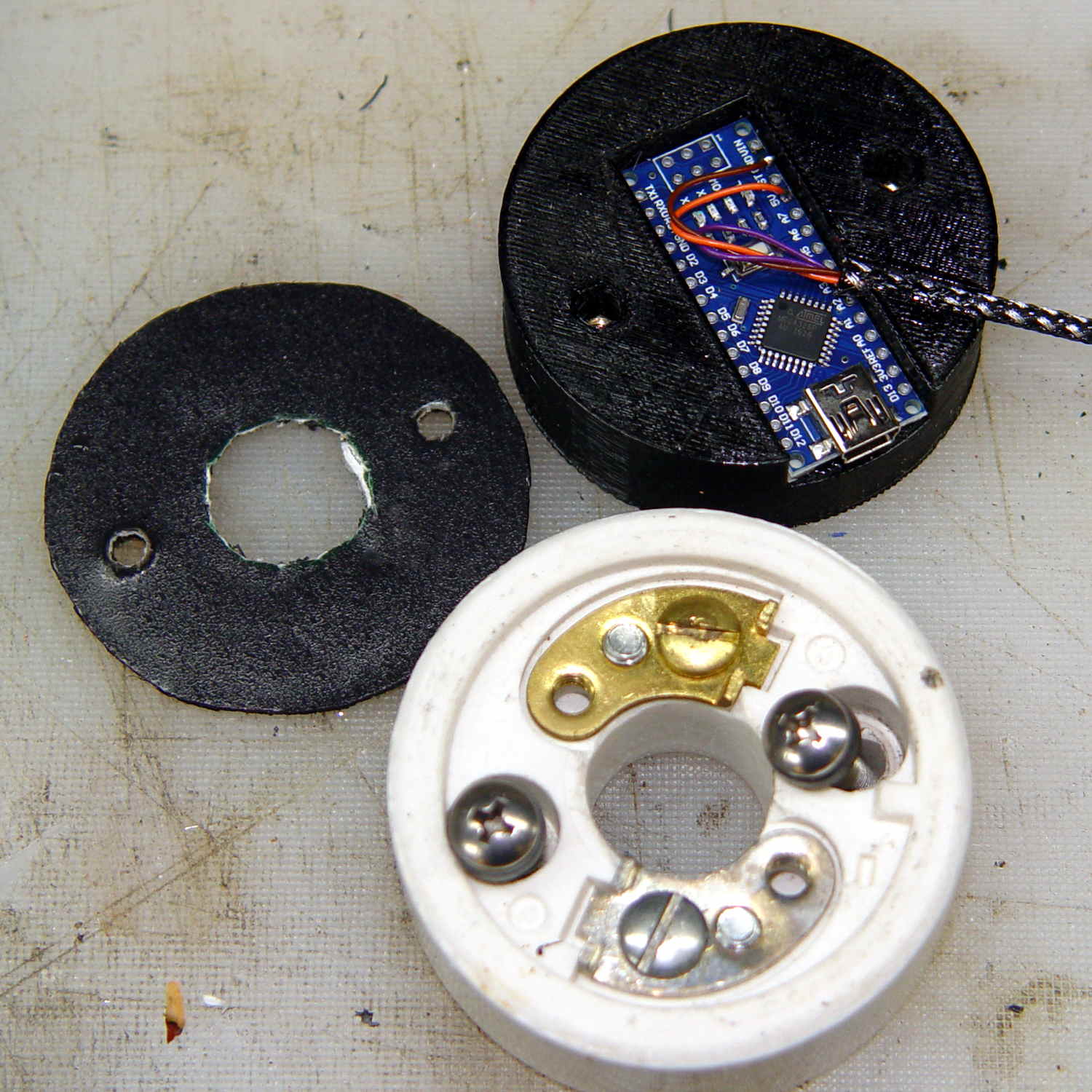
The Arduino Nano fits inside a small base below the ceramic Mogul socket:
Mogul base – Arduino Nano holder
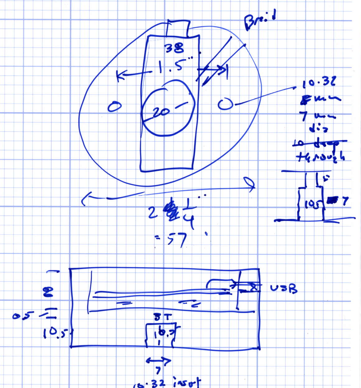
The braid exits through a hexagonal trench recessed into the top surface, with a dollop of epoxy holding it in place:
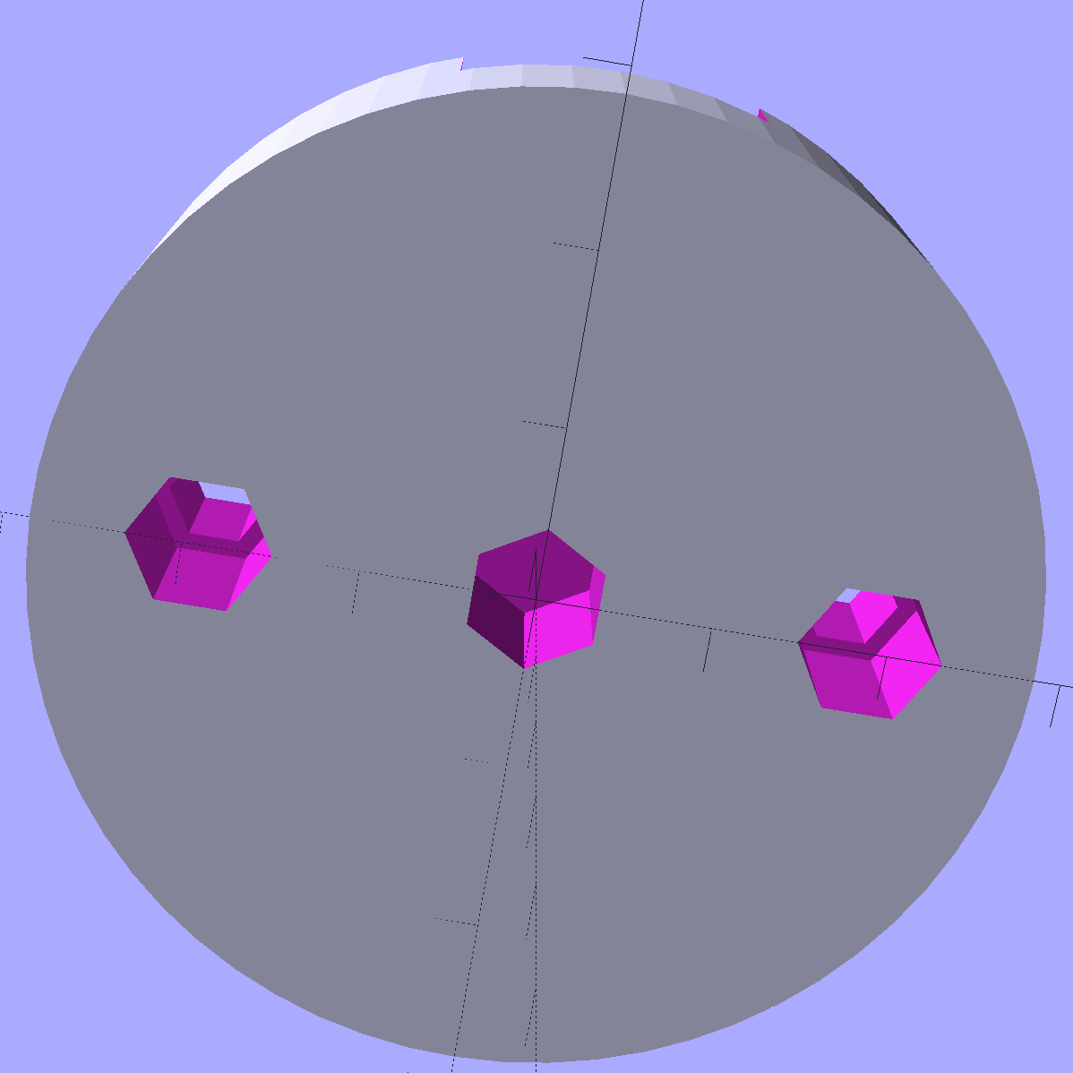
Vacuum Tube Lights – Mogul Base – top – solid model
The underside has holes for three 10-32 brass inserts:
Vacuum Tube Lights – Mogul Base – bottom – solid model
The center insert is the only thing holding the entire assembly to that aluminum base; I’m not convinced that’s enough, but it’ll suffice for now.
The “computer” certainly gets lost under the ceramic:
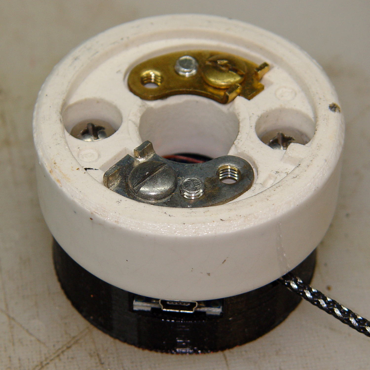
Mogul base – ceramic socket connector
The base is slightly smaller than the ceramic to match the flat part of the lower surface; if it came all the way to the OD, you’d see an unsightly notch.
The two screw heads buried down in the recesses thread into the outer brass inserts in the printed base. The ceramic Mogul socket mounts atop that connection block, with another pair of screws making both electrical and mechanical connections to the metal plates-with-screws that used to terminate the incoming power wires.
It’s running the same Morse code firmware as before, with the Morse output turned off, because who needs a giant blinking bulb?
The OpenSCAD source code of the base as a GitHub Gist:
This file contains hidden or bidirectional Unicode text that may be interpreted or compiled differently than what appears below. To review, open the file in an editor that reveals hidden Unicode characters.
Learn more about bidirectional Unicode characters
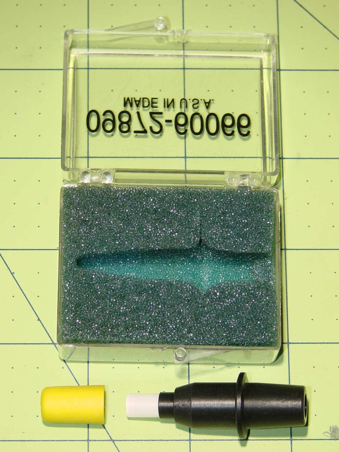
I found this antique on eBay for (somewhat) under HP’s 1980-era $35 price:
HP 09872-60066 Digitizing Sight – overview
The prevailing price for HP 09872-60066 Digitizing Sights seems to be $100 and upwards, with outliers in both directions, so I just couldn’t pass it up.
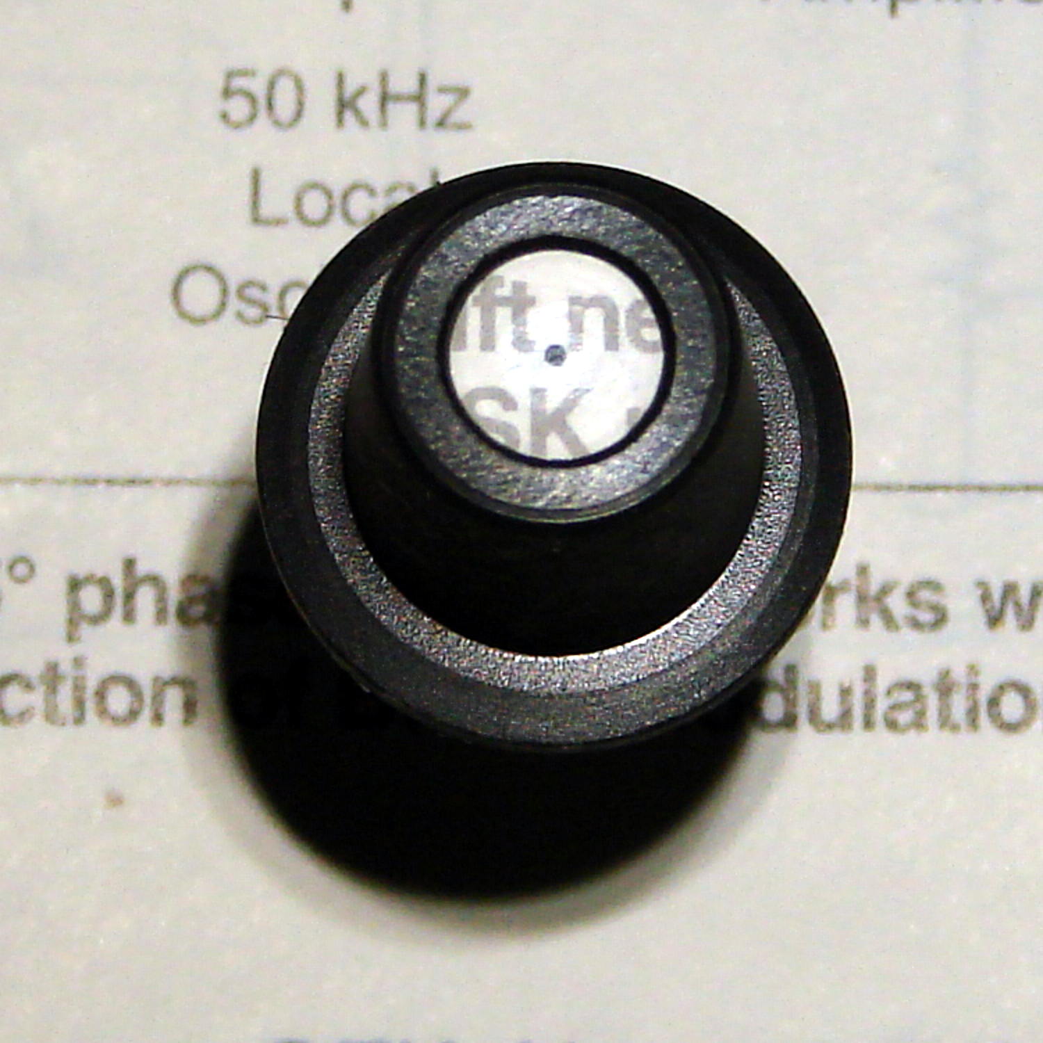
Anyhow, the fiber optic pipe still works just like it did, back in the day:
HP 09872-60066 Digitizing Sight – text target
The small dot in the middle is actually a paint-filled indentation on the bottom surface:
HP 09872-60066 Digitizing Sight – bottom detail
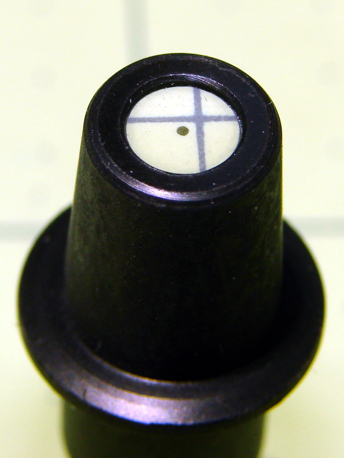
With the bottom flat on the target, the relayed image is in perfect focus:
HP 09872-60066 Digitizing Sight – top detail
The bezel recesses the top surface by 25 mil to protect the imaging plane.
OK, it’s a gadget gloat; I have absolutely no intention of ever chucking a piece of paper in the plotter and digitizing any points.