The Smell of Molten Projects in the Morning

Ed Nisley's Blog: Shop notes, electronics, firmware, machinery, 3D printing, laser cuttery, and curiosities. Contents: 100% human thinking, 0% AI slop.

Author: Ed

  • MPCNC: Spirograph Exerciser

    Both bCNC and GCMC include Spirograph generators with more-or-less fixed patterns and sizes, because the code serves to illustrate the software’s capabilities:

    MPCNC - bCNC Spirograph patterns
    MPCNC – bCNC Spirograph patterns
    GGMC Cycloids test patterns
    GGMC Cycloids test patterns

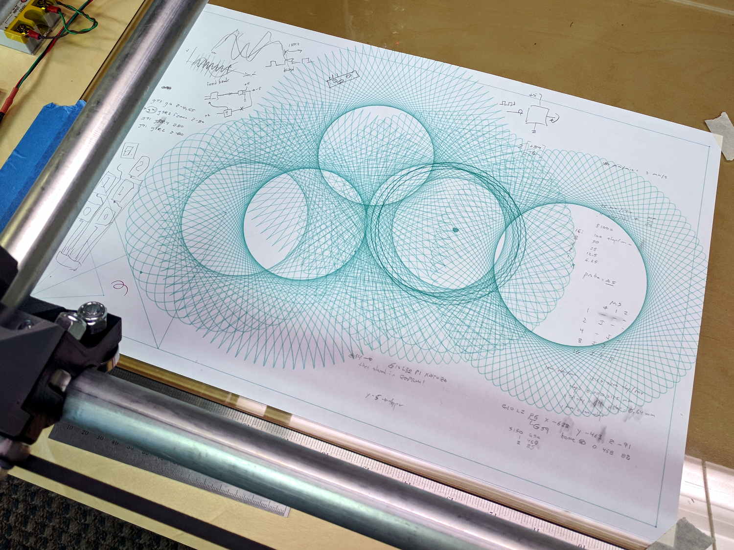
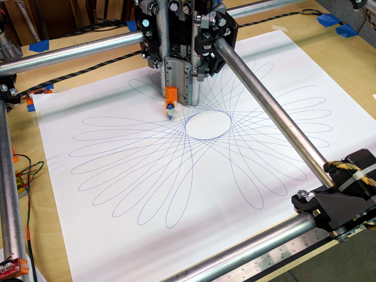
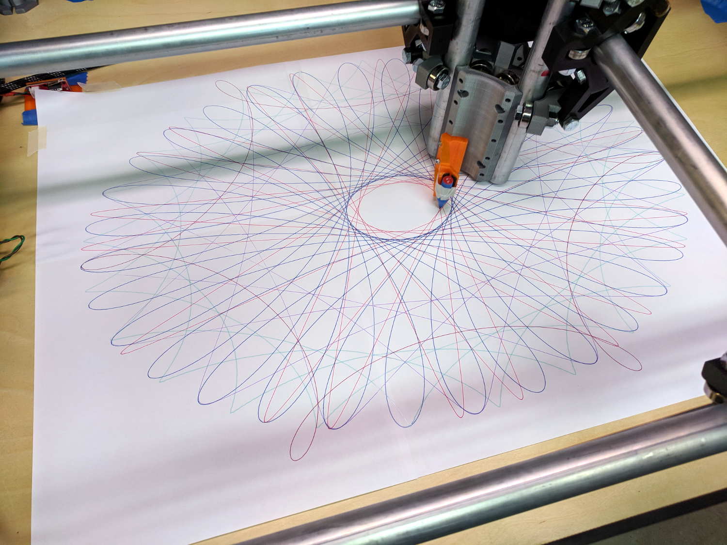
    I wanted to exercise my MPCNC’s entire range of travel, familiarize myself with some new GCMC features, and, en passant, mimic the actual gears in a classic Spirograph, so, of course, I had to write a Spirograph emulator from scratch:

    MPCNC - Full-platform Spirograph - multicolor
    MPCNC – Full-platform Spirograph – multicolor

    The perspective makes a 29×19 inch sheet of paper (made from three B sheets and one A sheet) look not much larger than the 17×11 inch B size sheets in the first two pictures. IRL, it’s a billboard!

    My GCMC code uses notation and formulas from a paper (tidy PDF) on a Gnuplot spirograph generator, with a dash of error checking from the GCMC source.

    The code enumerates the possible gear tooth counts in a pair of vectors from which you select the desired stator and rotor gears using integer subscripts. Because I eventually scale the results to fit the plot area, there’s no need to keep track of actual gear pitch diameters.

    Similarly, the pen offset from the center of the rotor gear is a pure number, which you can think of as the ratio of the offset to the rotor diameter. It can have either sign and may exceed unity, as needed, either of which would be difficult with a physical gear.

    Figuring the number of rotor turns required to complete the pattern requires reducing the gear ratio to a fraction with no common factors, so I wrote a Greatest Common Divisor function using Euclid’s algorithm adapted for GCMC’s bitwise tests and shifts.

    With those values in hand, a loop iterates around the entire pattern to produce a list of XY coordinates in normalized space. Because the formula doesn’t have the weird properties of the Superformula I used with the HP 7475 plotter, I think there’s no need to prune the list to eliminate tiny moves.

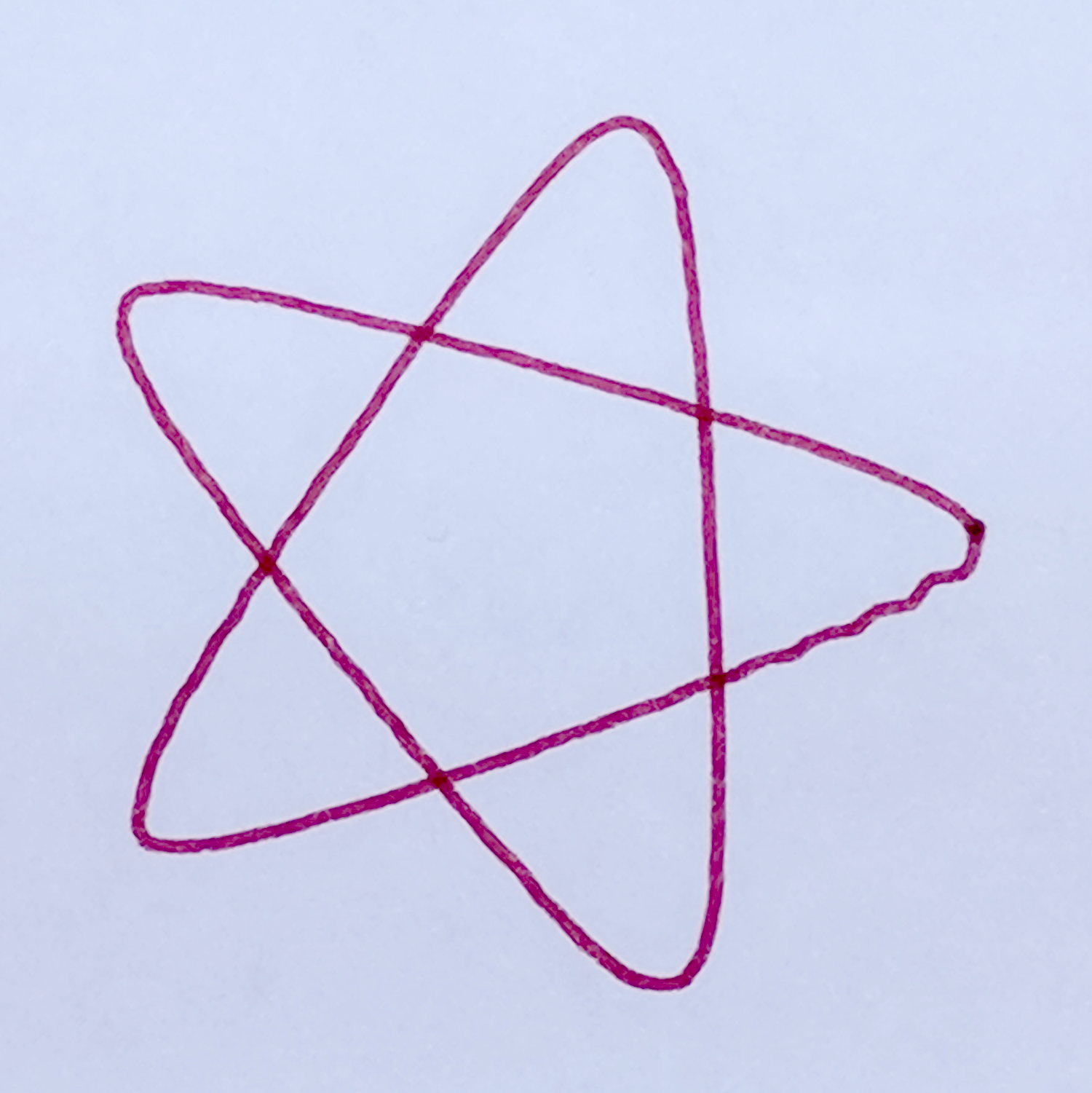
    Scaling the entire plot requires keeping track of the actual extents along both axes, which happens in the loop generating the normalized coordinates. A pair of gears producing an odd number of lobes can have different extents in the positive and negative directions, particularly with only a few lobes (3, 5, 7 …):

    Spirograph - 3 lobes - QnD Simulator
    Spirograph – 3 lobes – QnD Simulator

    So I accumulate all four, then scale based on the absolute maximum; I added scalar min() and max() functions.

    Converting the list of scaled points into G-Code turns out to be a one-liner using GCMC’s tracepath() library function. Previewing the results in a Web-based simulator helps weed out the duds.

    The code needs cleanup, in particular to let a Bash script set various parameters, but it’s a good start.

    The GCMC source code as a GitHub Gist:

    // Spirograph simulator for MPCNC plotter
    // Ed Nisley KE4ZNU – 2017-12
    // Spirograph equations:
    // https://en.wikipedia.org/wiki/Spirograph
    // Loosely based on GCMC cycloids.gcmc demo:
    // https://gitlab.com/gcmc/gcmc/tree/master/example/cycloids.gcmc
    include("tracepath.inc.gcmc");
    //—–
    // Greatest Common Divisor
    // https://en.wikipedia.org/wiki/Greatest_common_divisor#Using_Euclid's_algorithm
    // Inputs = integers without units
    function gcd(a,b) {
    local d=0;
    // message("gcd(" + a + "," + b + ") = ");
    if (!isnone(a) || isfloat(a) || !isnone(b) || isfloat(b)) {
    warning("Values must be dimensionless integers");
    }
    while (!((a | b) & 1)) { // remove and tally common factors of two
    a >>= 1;
    b >>= 1;
    d++;
    }
    while (a != b) {
    if (!(a & 1)) {a >>=1;} // discard non-common factor of 2
    elif (!(b & 1)) {b >>= 1;} // … likewise
    elif (a > b) {a = (a – b) >> 1;} // gcd(a,b) also divides a-b
    else {b = (b – a) >> 1;} // … likewise
    }
    g = a*(1 << d); // form gcd
    // message(" " + g);
    return g;
    }
    //—–
    // Max and min functions
    function max(x,y) {
    return (x > y) ? x : y;
    }
    function min(x,y) {
    return (x < y) ? x : y;
    }
    //—–
    // Spirograph tooth counts mooched from:
    // http://nathanfriend.io/inspirograph/
    Stators = [96, 105, 144, 150];
    Rotors = [24, 30, 32, 36, 40, 45, 48, 50, 52, 56, 60, 63, 64, 72, 75, 80, 84];
    //—–
    // Set up gearing
    s = 1; // index values should be randomized
    r = 6;
    StatorTeeth = Stators[s]; // from the universe of possible teeth
    RotorTeeth = Rotors[r];
    message("Stator: ", StatorTeeth);
    message("Rotor: ", RotorTeeth);
    L = 0.90; // normalized pen offset in rotor
    message("Pen offset: ", L);
    g = gcd(StatorTeeth,RotorTeeth); // reduce teeth to ratio of least integers
    StatorN = StatorTeeth / g;
    RotorM = RotorTeeth / g;
    K = to_float(RotorM) / to_float(StatorN); // normalized rotor dia
    Lobes = StatorN; // having removed all common factors
    Turns = RotorM;
    message("Lobes: ", Lobes);
    message("Turns: ", Turns);
    AngleStep = 2.0deg;
    //—–
    // Crank out a list of points in normalized coordinates
    Path = {};
    Xmax = 0.0;
    Xmin = 0.0;
    Ymax = 0.0;
    Ymin = 0.0;
    for (a=0.0deg ; a <= Turns*360deg ; a += AngleStep) {
    x = (1 – K)*cos(a) + L*K*cos(a*(1 – K)/K);
    if (x > Xmax) {Xmax = x;}
    elif (x < Xmin) {Xmin = x;}
    y = (1 – K)*sin(a) – L*K*sin(a*(1 – K)/K);
    if (y > Ymax) {Ymax = y;}
    elif (y < Ymin) {Ymin = y;}
    Path += {[x,y]};
    }
    message("Max X: ", Xmax, " Y: ", Ymax);
    message("Min X: ", Xmin, " Y: ", Ymin); // min will always be negative
    Xmax = max(Xmax,-Xmin); // odd lobes can cause min != max
    Ymax = max(Ymax,-Ymin); // … need really truly absolute maximum
    //—–
    // Scale points to actual plot size
    TableSize = [25in,18in]; // largest possible plot area
    PaperSize = 0 ? [17.0in,11.0in] : TableSize;
    Margins = [0.5in,0.5in] * 2;
    Boundary = PaperSize – Margins;
    message("Boundary: ",Boundary);
    PlotScale = [Boundary.x / (2*Xmax), Boundary.y / (2*Ymax)];
    message("Plot scale: ", PlotScale);
    Points = scale(Path,PlotScale); // fill page, origin at center
    //—–
    // Produce G-Code
    feedrate(6000.0mm);
    safe_z = [-,-,25.0mm];
    plotz = -1.0mm;
    goto([0,0,10.0mm]);
    tracepath(Points, plotz);
    goto(safe_z);

  • MPCNC: GCMC Spirograph Shakedown

    The MPCNC instructions recommend running it for a while, taking it apart, then putting it back together, so all the parts have a chance to relax and get used to working together. To that end, I figured doing some full platform plots would run the rollers over the entire length of the rails:

    MPCNC - Full-platform Spirograph - first pass
    MPCNC – Full-platform Spirograph – first pass

    I taped three B-size sheets together, with an A-size sheet in the far right corner, into a 29×19 inch sheet to put borders around the MPCNC’s 28×18 inch work area. The tape is on the top surface to prevent embarrassing accidents where the pen snags on an edge, at the cost of blurry lines where the ink doesn’t stick quite right.

    The far left corner of the paper washes up on the tool length probe’s base, but the pen position turns out to be so repeatable (it should be!) you can swap them with gleeful abandon and get good results:

    MPCNC - Full-platform Spirograph - multicolor
    MPCNC – Full-platform Spirograph – multicolor

    The pen rumbles along at 12000 mm/min = 200 mm/s = 7.8 inch/s with no hint of wobblulation. Most likely, those big loops aren’t particularly challenging, although watching the big central assembly whip around a tight curve can be startling.

    I modified the pen holder for 3-point support, as the recess for the pen flange isn’t quite deep enough:

    MPCNC - Pen holder - 3 point grip
    MPCNC – Pen holder – 3 point grip

    Good old masking tape holds the pens securely enough for now.

    The glass plate I’d been using for B-size plots doesn’t cover the full area, but I’d set the Z axis limit switch to trip just before the bottom of the rails whacked into the glass. Extending the travel by 5 mm required a snippet of black tape:

    MPCNC - Z axis switch - table limit
    MPCNC – Z axis switch – table limit

    The patterns come from a scratch-built Spirograph generator, because I wanted to review what’s new in GCMC. More on the software tomorrow …

  • MPCNC: Pen Wobble

    GCMC includes cycloids.gcmc, a test program producing a fixed set of hypotrochoids and epitrochoids, more commonly known as Spirograph patterns:

    GGMC Cycloids test patterns
    GGMC Cycloids test patterns

    I’m using them to get familiar with bCNC’s Workspace Coordinate System settings and to exercise the MPCNC hardware; ya gotta plot before you can cut.

    Most came out fine, but some showed distinct wobbles:

    MPCNC - Cycloid wobble - star
    MPCNC – Cycloid wobble – star

    Tight curves and higher speeds produce more wobbles:

    MPCNC - Cycloid wobble - loops
    MPCNC – Cycloid wobble – loops

    You’d probably never feed a wood router over 6000 mm/min = 240 inch/min, so this isn’t as much of a problem as it might appear. Also, I expect a few pounds of router will have fewer wobbulations than a weightless pen hung on a thin plastic mount:

    MPCNC - Pen Holder Detail
    MPCNC – Pen Holder Detail

    Just one more thing to keep in mind.

  • MPCNC: Tool Length Probe, Reshaped for Plotter Pens

    It turns out old-school plotter pen nibs skid right off the rounded top of the switch lever:

    MPCNC Tool Length Probe - plotter pen
    MPCNC Tool Length Probe – plotter pen

    You can’t see the nib inside the cap, but you get the idea.

    Flattening the top and adding a snippet of masking tape produces a better outcome:

    MPCNC - Reshaped Tool Probe switch
    MPCNC – Reshaped Tool Probe switch

    I aligned the flat section so it’s parallel to the platform when the switch activates.

    Stipulated: plotter pens aren’t a good test for tool length probing, because they have a locating flange to ensure a consistent position in the pen holder and a rigidly controlled flange-to-tip length:

    HP 7475A Plotter Pen Body - in holder
    HP 7475A Plotter Pen Body – in holder

    What’s going on here involves configuring and testing bCNC’s overall tool change process: not using cutting tools preserves both sanity and hardware!

  • Monthly Image: Rt 376 Repaving

    NYS DOT repaved the section of Rt 376 between our house and the Red Oaks Mill intersection during a mid-October week, doing most of the work overnight to avoid jamming traffic to the horizon in all directions. Having nothing better to do, I supervised the proceedings …

    They prepared the surface by milling off the old pavement during three successive nights, which was just about as noisy as you’d think:

    Rt 376 Repave - milled surface
    Rt 376 Repave – milled surface

    The asphalt spreader sported bizarre LED lights:

    Rt 376 Repave - Spreader in Wait
    Rt 376 Repave – Spreader in Wait

    Southbound paving began with a crisp new truck:

    Rt 376 Repave - Starting southbound
    Rt 376 Repave – Starting southbound

    He would look the same rolling a highway straight through Hades:

    Rt 376 Repave - Rolling
    Rt 376 Repave – Rolling

    The short truck cleared the overhead wire:

    Rt 376 Repave - Southbound under wire
    Rt 376 Repave – Southbound under wire

    Then they chucked up a series of longer Flow Boy trailers:

    Rt 376 Repave - Feathering the Edge
    Rt 376 Repave – Feathering the Edge

    Despite all the machinery, the job requires guys with rakes and shovels.

    All the pictures come from the Pixel, hand-held with automagic exposure and HDR+.

    My tax dollars were definitely awake and hard at work during those nights!

  • MPCNC: GCMC Configuration

    The default GCMC prolog(ue) spits out some G-Codes that GRBL doesn’t accept, requiring tweaks to the incantation.

    A first pass at a useful prolog, minus the offending codes:

    cat ~/.config/gcmc/prolog.gcmc 
    (prolog begins)
    G17 (XY plane)
    G21 (mm)
    G40 (no cutter comp)
    G49 (no tool length comp)
    G80 (no motion mode)
    G90 (abs distance)
    G94 (units per minute)
    (prolog ends)
    

    Including any of the usual “end of program” M-Codes in the epilog(ue) causes GRBL to pause before exiting the program, so leave only a placeholder:

    cat ~/.config/gcmc/epilog.gcmc 
    (epilog begins)
    (M2) (allow program to continue)
    (epilog ends)
    

    Having done a git clone into /opt/gcmc before building the program, the GCMC library routines live in:
    /opt/gcmc/library

    Limiting numeric values to two decimal places makes sense:
    -P 2

    With all that in hand, unleashing the compiler on an unsuspecting source file requires this jawbreaker:

    gcmc -P 2 -I /opt/gcmc/library \
    -G ~/.config/gcmc/prolog.gcmc \
    -g ~/.config/gcmc/epilog.gcmc \
    -o cycloids.ngc \
    cycloids.gcmc
    

    One might, of course, tuck all that into a little script, rather than depend on extracting it from the bash history as needed.

    The resulting G-Code file looks about right:

    head cycloids.ngc
    (prolog begins)
    G17 (XY plane)
    G21 (mm)
    G40 (no cutter comp)
    G49 (no tool length comp)
    G80 (no motion mode)
    G90 (abs distance)
    G94 (units per minute)
    (prolog ends)
    F2500.00
    [pi@MPCNC tmp]$ head -25 cycloids.ngc
    (prolog begins)
    G17 (XY plane)
    G21 (mm)
    G40 (no cutter comp)
    G49 (no tool length comp)
    G80 (no motion mode)
    G90 (abs distance)
    G94 (units per minute)
    (prolog ends)
    F2500.00
    G0 Z1.00
    (-- tracepath at Z=-1.00mm --)
    G0 X-145.50 Y-30.00
    G1 Z-1.00
    G1 X-145.51 Y-29.93
    
    ... vast snippage ...
    
    G1 X175.50 Y30.00
    G1 Z1.00
    G0 Z25.00
    (epilog begins)
    (M2)
    (epilog ends)
    

    Then it’s just a matter of tweaking cycloids.gcmc to make interesting things happen:

    GGMC Cycloids test patterns
    GGMC Cycloids test patterns
  • MPCNC: Tool Length Probe Station

    Having a tool length probe station on the Sherline, I had to build one for the MPCNC:

    MPCNC Tool Length Probe - plotter pen
    MPCNC Tool Length Probe – plotter pen

    It’s little more than a flange atop a wide base:

    MPCNC Tool Length Probe - Slic3r preview
    MPCNC Tool Length Probe – Slic3r preview

    The flange offset puts the switch actuator on the midline of the base, not that that matters, and the base features rounded corners and a suitable legend, because I can.

    I clipped the PCB’s through-hold leads nearly flush and stuck it to the flange with 3M permanent foam tape, which seems to work much better than screws & inserts for simple things that need never come apart.

    The Protoneer CNC Shield includes a Probe input on the GRBL-compliant A5, although it took me a while to find the legend on the SCL pin in the I2C header. I moved the endstop power jumper to another header, then conjured a quick-and-dirty connector:

    Protoneer CNC Shield - Tool Probe Wiring
    Protoneer CNC Shield – Tool Probe Wiring

    When I embed the endstop switch PCB in epoxy, I’ll add a drop to the connector while engaging in Magical Thinking. The whole Arduino + CNC Shield must go into an enclosure after I finish measuring the motor currents.

    To forestall discussions about switch repeatability and accuracy, suffice it to say the MPCNC doesn’t claim to be much more than a woodworking router, so those switches seem Good Enough.

    The OpenSCAD source code as a GitHub Gist:

    // MPCNC Tool Length Probe Station
    // Ed Nisley KE4ZNU – 2017-12-08
    /* [Extrusion] */
    ThreadThick = 0.25; // [0.20, 0.25]
    ThreadWidth = 0.40; // [0.40]
    function IntegerMultiple(Size,Unit) = Unit * ceil(Size / Unit);
    /* [Hidden] */
    Protrusion = 0.1; // [0.01, 0.1]
    HoleWindage = 0.2;
    /* [Sizes] */
    EndstopPCB = [40.0,16.5,1.6]; // endstop PCB
    ComponentHeight = 6.0; // max component height above PCB
    SwitchOffset = [35.0,21.0,4.75]; // touch point center from lower left PCB corner
    SwitchTravel = 2.5; // first touch to switch actuation
    TapeThick = 1.0; // foam mounting tape
    WallThick = 4.0; // basic wall & floor thickness
    BaseRadius = 5.0;
    Base = [IntegerMultiple(EndstopPCB[0] + 2*BaseRadius,20),
    IntegerMultiple(EndstopPCB[2] + TapeThick + WallThick + 2*BaseRadius,2*25),
    2.0];
    NumSides = 8*4;
    TextDepth = 2*ThreadThick;
    //- Build it
    union() {
    difference() {
    hull()
    for (i=[-1,1], j=[-1,1])
    translate([i*(Base[0]/2 – BaseRadius),j*(Base[1]/2 – BaseRadius),0])
    resize([0,0,Base[2]])
    intersection() {
    cylinder(r=BaseRadius,h=BaseRadius,$fn=NumSides);
    sphere(r=BaseRadius,$fn=NumSides);
    }
    translate([0,0,Base[2] – TextDepth])
    linear_extrude(height=TextDepth + Protrusion) {
    translate([0,-10,0])
    text(text="MPCNC",size=8,spacing=1.05,font="Arial:style=Bold",halign="center");
    translate([0,-18,0])
    text(text="Tool Probe",size=6,spacing=1.05,font="Arial:style=Regular",halign="center");
    }
    }
    translate([0,
    WallThick/2 + TapeThick + SwitchOffset[2],
    (EndstopPCB[1] – Protrusion)/2 + Base[2]])
    cube([EndstopPCB[0],WallThick,EndstopPCB[1] + Protrusion],center=true);
    }

    The original doodles show a severely over-complexicated solution desperately searching for an actual problem:

    MPCNC Tool Length Probe - doodles
    MPCNC Tool Length Probe – doodles

    Putting a large flat pan at the end of a relatively long lever arm, with the pivot arranged to put the pan level at the switch actuation point, made sense at the time. Give the relatively small tools I expect to use, directly ramming them into the switch lever should work just as well.

    Putting all that complexity in harm’s way seemed like a Bad Idea when I sat down and looked at it in cold blood.