The Smell of Molten Projects in the Morning

Ed Nisley's Blog: Shop notes, electronics, firmware, machinery, 3D printing, laser cuttery, and curiosities. Contents: 100% human thinking, 0% AI slop.

Author: Ed

  • Reading a Vernier Height Gage

    The first time around, I simply set both pairs of MPCNC rails to equal heights using my height gage (*) as a reference, rather than as a measurement tool:

    MPCNC - Rail height measurement
    MPCNC – Rail height measurement

    By now, I assume all the plastic bits have shaken themselves down and the rails have settled into their more-or-less permanent locations, so it’d be useful to measure the actual rail heights and adjust as needed. The scale along the vertical bar of the height gage gives the height of the top surface of the projecting arm above the bench:

    Brown and Sharpe 585 Height Gage
    Brown and Sharpe 585 Height Gage

    Normally, the gage base would sit on a surface plate. Building an MPCNC on a big granite slab would certainly cut down on the shakes from overly enthusiastic acceleration settings!

    The nicely reshaped and polished lathe bit transfers the top surface of the gage arm to the top of the MPCNC rail, so whatever height shows up on the vernier gives the rail height. The exact value, of course, doesn’t really matter in this situation, but when you need an actual measurement, it’s got you covered.

    The two brackets slide along the height gage, with the thumbscrews on the right locking them in position. To measure a height, you loosen both thumbscrews, slide the whole affair to put the arm bracket at about the right height, tighten the top thumbscrew to anchor the adjusting bracket, twirl the knurled wheel to precisely position the arm bracket, then read the height from the scale.

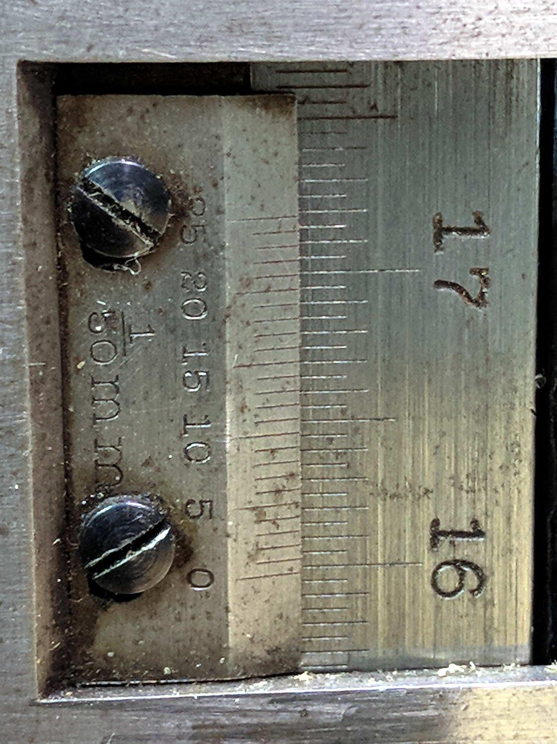
    This requires reading a vernier height gage scale:

    Vernier Height Gage - 132.20 mm
    Vernier Height Gage – 132.20 mm

    The other scale on the other side has inches, but nobody uses those any more. Right?

    Things I didn’t get quite right the first time around:

    • The numbers along the right side are in centimeters
    • The smallest lines on that scale mark 0.5 mm increments
    • The numbers on the vernier have units of 1/50 mm = 0.02 mm

    So, to read the scale:

    • Multiply centimeters by 10 to get millimeters: 130
    • Add the number of whole millimeters below the 0 vernier index: 2
    • Add a half millimeter if needed: 0
    • Find the matching vernier increment: 10
    • Multiply the increment by 2: 20
    • Slap the decimal point two places left and add: 132.20

    OK, try this one:

    Vernier Height Gage - 159.84 mm
    Vernier Height Gage – 159.84 mm

    As I see it:

    • Read 15 cm
    • Count 9 ticks
    • Add the 0.5 mm tick
    • Match vernier tick 17, multiply and slap decimal = 0.34 mm
    • Add: 150 + 9 + 0.5 + 0.34 = 159.84 mm

    There, now, that wasn’t so hard, was it?

    There’s obviously a parallax issue between the edge of the vernier scale and the main scale; it’s easier to get it right in person than in the photograph.

    I pronounced the reading as “160 minus point 5 is 159 and a half plus point 34 is point 84”, but I also take eight photographs as I work my way around the MPCNC frame to review any suspicious results.

    Obviously, reading a digital height gage would be much easier & faster, but we don’t want to deskill the workforce, do we?

    The maker’s mark on my height gage says it’s a Brown & Sharpe 585 with a 19 inch scale; B&S has long since been Borged. Back in the day, this painstakingly applied etching distinguished it from all the other height gages in the shop:

    Brown and Sharpe 585 Height Gage - D.E 1-I-3 etching
    Brown and Sharpe 585 Height Gage – D.E 1-I-3 etching

    We’ll never know the rest of the story.

    (*) When Starrett spells it “gage”, it’s good enough for me.

  • Blog Summary: 2017

    Page views for 2017:

    Top Posts 2017
    Top Posts 2017

    Plumbing and car troubles continue to plague folks in Search Engine City.

    If I could monetize my broom handle thread IP, I’d be rich, I tell you, rich.

    Some interesting (and rounded) numbers from the ads you (presumably) don’t see, because adblocking.

    The blog gets just under 30 k page views/month, call it 1 k/day. Because most of the traffic arrives from search engines, each viewer looks at only 1.6 pages. Dividing the two suggests 18 k viewers/month.

    WordPress now shows 90 k ad impressions/month. Dividing 90 k impressions by 18 k viewers gives 5 ad impressions/viewer, which is about what you’d expect from the three ads appearing on the main page and each post seen individually: 3 ads/page × 1.6 page views/visitor = 4.8 ads/visitor.

    Before the big WP advertising push, they reported 15 k ad impressions/month for roughly the same 30 k page views/month and 1.6 pages/visitor. At one ad per page (which I don’t know for sure, but it seems reasonable), 30 k views should produce 30 k ad impressions. I can’t account for the discrepancy.

    Those of you using ad blockers (which I highly recommend!) don’t know what you’re missing.

    Onward, into the New Year …

  • Sundog

    The ice behind this sundog foretold a snowstorm:

    Sundog
    Sundog

    When I first saw it, the contrail bisected the sundog, but we had to walk to a safer spot before I could fumble with the Pixel.

    See? I’m not always searching for treasures amid the roadside trash

  • Roadside Jewelry

    I spotted a piece of jewelry during a recent walk:

    Headlight Condenser - rear
    Headlight Condenser – rear

    The other side shows off The Shiny Bit:

    Headlight Condenser - front
    Headlight Condenser – front

    I seem to have swapped the “front” and “rear” labels; the flat side faces the LED / HID bulb.

    It looked even better after extraction and casual cleaning:

    Headlight Condenser - sunlit
    Headlight Condenser – sunlit

    It seems someone with a relatively new car had a fairly high energy accident just north of Red Oaks Mill. The remainder of the debris consisted of shattered engineering plastic. We’ll never know the rest of the story.

    Both lens surfaces have a slight nubbly finish, perhaps to produce some side light around the main beam. The rectangular opening apparently shaped the low beam and doesn’t appear movable, so perhaps the car had separate headlights for the high beams.

    I’m not quite sure what to do with a chipped condenser lens, so it’s sitting on the windowsill (in a sun-safe orientation) along with many other glittery bits of glass I’ve collected over the years.

  • Pogo Pins

    A Pogo Pin reference may be useful:

    • P.. and R.. refer to Pin and Receptacle (a.k.a. socket), respectively
    • Pxx  and Rxx = nominal pin diameter in 0.01 mm units: P50 = 0.48 mm

    For pins, the suffix -hn indicates pin head shape, the most useful of which may be:

    • B1: 45° cone
    • J1: dome end
    • Dx: large dome, also 1D
    • Gx: cylinder
    • Ex: large 90° cone, sometimes 1E
    • T2 – large chisel

    For sockets, the suffix -ntl gives:

    • n – entry shape: 1 = shaped entry, 2 = straight entry
    • t – termination: C = crimp, S = solder, W = wire
    • l – length of wire in 100 mm units: 7 = 700 mm

    From what I can find on eBay, all pins have 6 mm travel with typically 75 / 100 / 180 g spring force.

    A picture ripped from the reference to forestall link rot:

    P75 Spring Test Probes
    P75 Spring Test Probes

    Memo to Self: US-based eBay sellers charge three times more than Chinese sellers, but deliver in one-third the time.

    [Update: Simon sends a link to Everett Charles Technologies, a pogo-pin manufacturer providing “Probably much more information than anyone should ever want”. Of course, eBay / Amazon junk may not meet any particular specs, so scale your expectations accordingly.]

  • MPCNC: Plotter Pen Holder Spring Constant

    Watching the MPCNC plot Spirograph patterns led me to wonder about how much force the printed drag knife holder applies to the pen:

    Spirograph - liquid ink pen - detail
    Spirograph – liquid ink pen – detail

    The HP 7475A plotter spec calls for 19 g = 0.67 oz of downward force on the pen, so, in an ideal world, one might want to use one’s collection of aging plotter pens in a similar manner.

    Plotter pen, meet digital scale:

    MPCNC - Plotter pen force test
    MPCNC – Plotter pen force test

    Stepping the pen downward in 0.1 mm increments produced a set of numbers and a tidy linear fit graph:

    MPCNC Plotter Pen Holder - Spring Constant
    MPCNC Plotter Pen Holder – Spring Constant

    I hereby swear I’m not making things up: the spring constant really is a nice, round 100 g/mm!

    I set plot_z = -1.0 in the GCMC program, with Z=0.5 touched off atop a defunct ID card on the paper surface to compensate for any tabletop warp / bow / misalignment, plus any errors from the tool length probe. An eyeballometric scan against a straightedge shows pretty nearly no misalignment, which means the holder mashes the pen against the paper with about 100 g of force, five times the HP spec.

    A distinct case of pen abuse rears its ugly head.

    It’s time to conjure a height probe for the tool holder.

  • Spirograph Random Numbers: What Are The Odds?

    The GCMC Spirograph Generator program chooses parameters using pseudo-random numbers based on a seed fed in from the Bash script, so I was surprised to see two plots overlap exactly:

    Overlaid pattern - G-Code simulator
    Overlaid pattern – G-Code simulator

    The two overlapping traces are the 15 inward-pointing wedges around the central rosette.

    The first one:

    (PRNG seed: 38140045)
    (Paper size: [16.50in,14in])
    (PlotSize: [15.50in,13.00in])
    (Stator 3: 150)
    (Rotor  4: 40)
    (GCD: 10)
    (Offset: -0.94)
    (Dia ratio: -0.27)
    (Lobes: 15)
    (Turns: 4)
    (Plot scale: [5.11in,4.29in])
    (Tool change: 1)
    T1
    M6
    

    The second one:

    (PRNG seed: 74359295)
    (Paper size: [16.50in,14in])
    (PlotSize: [15.50in,13.00in])
    (Stator 3: 150)
    (Rotor  4: 40)
    (GCD: 10)
    (Offset: -0.93)
    (Dia ratio: -0.27)
    (Lobes: 15)
    (Turns: 4)
    (Plot scale: [5.12in,4.30in])
    (Tool change: 3)
    T3
    M6
    

    The Offset isn’t quite the same, but the pen width covers up the difference.

    With only four Stators and 17 Rotors, the probability of picking the same pair works out to 0.25 × 0.059 = 1.4%. You can sometimes get the same number of Lobes and Turns from several different Stator + Rotor combinations, but these were exact matchs with the same indices.

    The Pen Offset within the Rotor comes from a fraction computed with ten bit resolution, so each Offset value represents slightly under 0.1% of the choices. If any four adjacent values look about the same, then it’s only eight bits of resolution and each represents 0.4%.

    The Rotor and Stator set the Diameter ratio, but the sign comes from what’s basically a coin flip based on the sign of a fraction drawn from 256 possibilities; call it 50%.

    Overall, you’re looking at a probability of 28 ppm = 0.0028%, so I (uh, probably) won’t see another overlay for a while …

    I don’t know how to factor the PRNG sequence into those numbers, although it surely affects the probability. In this case, two different seeds produced nearly the same sequence of output values, within the resolution of my hack-job calculations.

    Whatever. It’s good enough for my simple purposes!