The Smell of Molten Projects in the Morning

Ed Nisley's Blog: Shop notes, electronics, firmware, machinery, 3D printing, laser cuttery, and curiosities. Contents: 100% human thinking, 0% AI slop.

Author: Ed

  • MPCNC: USB Camera Mount With Lock Screw

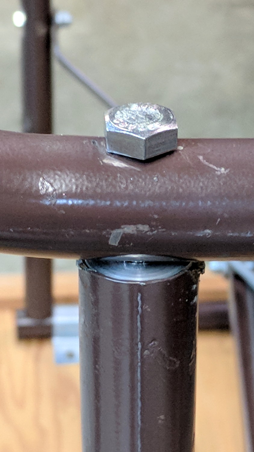
    It turned out the previous version of the USB camera mount lacked sufficient griptivity to hold the ball’s position against even moderate bumps, so the upper “half” is now tall enough to hold a lock screw directly over the ball:

    MPCNC - USB Camera mount - lock screw - Slic3r
    MPCNC – USB Camera mount – lock screw – Slic3r

    It doesn’t look much different:

    MPCNC - USB Camera Mount - lock screw
    MPCNC – USB Camera Mount – lock screw

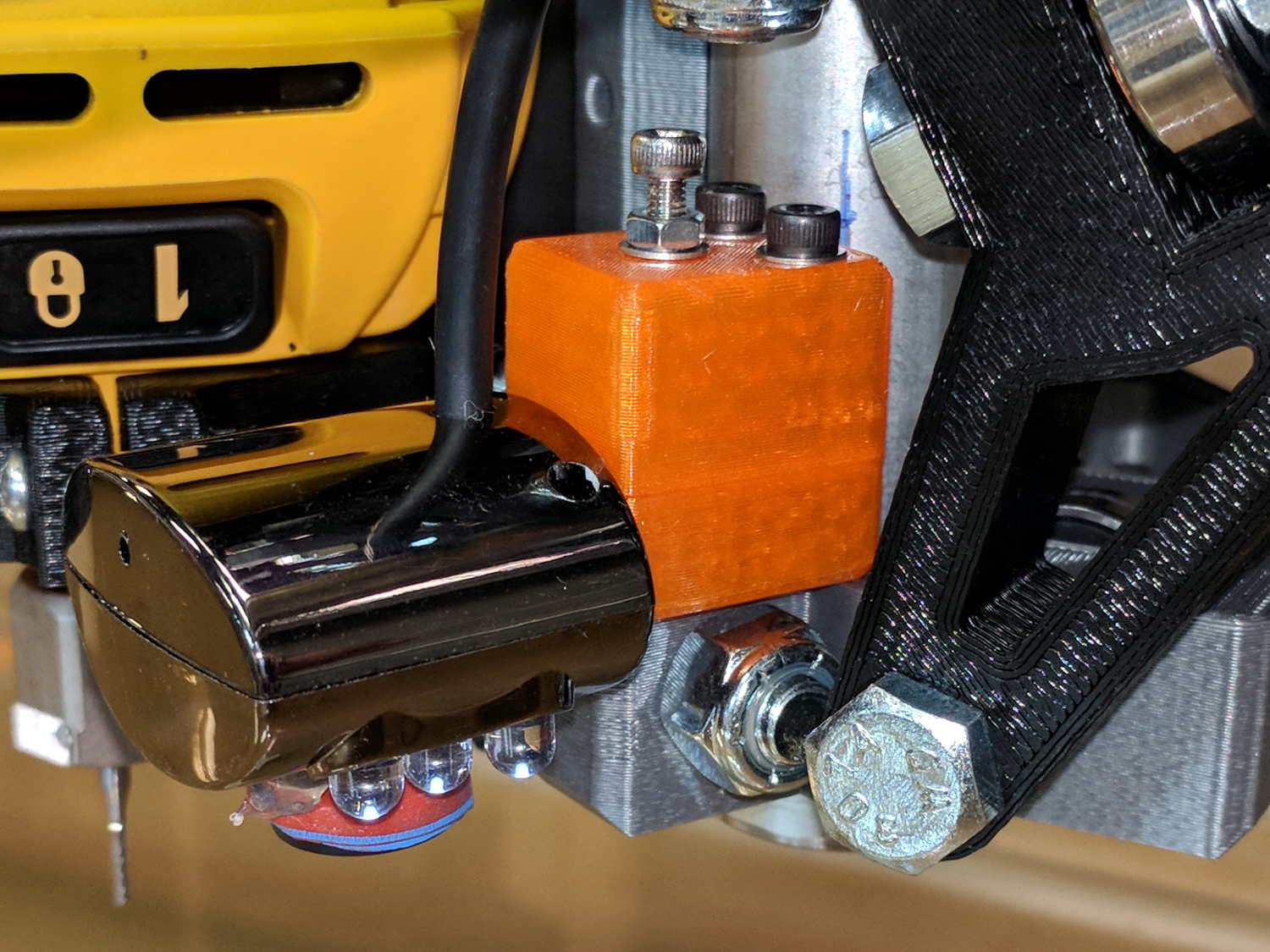
    A view from the other side:

    USB Camera - lock screw mount
    USB Camera – lock screw mount

    The previous iterations used Genuine 3M foam tape, which seemed too flexy for comfort. This one sits on a bed of hot melt glue and is absolutely rigid. We’ll see how long it survives.

    Tightening the cap screw requires needle-nose pliers, because the whole affair has no room for a hex key.

    The OpenSCAD source code as a GitHub Gist:

    // MPCNC USB Camera Mount
    // Ed Nisley KE4ZNU – 2018-02-22
    Layout = "Build"; // Build, Show
    /* [Extrusion] */
    ThreadThick = 0.25; // [0.20, 0.25]
    ThreadWidth = 0.40; // [0.40]
    /* [Hidden] */
    Protrusion = 0.1; // [0.01, 0.1]
    HoleWindage = 0.2;
    inch = 25.4;
    function IntegerMultiple(Size,Unit) = Unit * ceil(Size / Unit);
    ID = 0;
    OD = 1;
    LENGTH = 2;
    //- Adjust hole diameter to make the size come out right
    module PolyCyl(Dia,Height,ForceSides=0) { // based on nophead's polyholes
    Sides = (ForceSides != 0) ? ForceSides : (ceil(Dia) + 2);
    FixDia = Dia / cos(180/Sides);
    cylinder(r=(FixDia + HoleWindage)/2,h=Height,$fn=Sides);
    }
    //- Dimensions
    WallThick = 3.0; // minimum thickness / width
    CameraStalk = [6.0 + 1.0,10.0 + HoleWindage,4.0]; // stalk OD, ball OD, stalk length
    CameraAngle = -5; // stalk tilt, negative = downward
    Screw = [3.0,7.0,25.0]; // holding it all together, OD = washer
    Insert = [3.0,4.4,4.5]; // brass insert
    Pusher = Insert[LENGTH] / 2; // plastic locking snippet
    UpperThick = IntegerMultiple(CameraStalk[OD]/2 + Insert[LENGTH] + Pusher + WallThick,ThreadThick);
    LowerThick = Screw[LENGTH] – UpperThick;
    MountBlock = [24.0,20.0,LowerThick + UpperThick];
    echo(str("Block: ",MountBlock));
    NumSides = 6*4;
    //—–
    // Define shapes
    // Camera mount, enlongated for E-Z differencing
    // Origin at center of ball, stalk along +X
    module Camera() {
    union() {
    sphere(d=CameraStalk[OD],$fn=NumSides);
    rotate([0,90 – CameraAngle,0])
    PolyCyl(CameraStalk[ID],3*CameraStalk[LENGTH],NumSides);
    }
    }
    // Mount block with all the cutouts
    // Ball centerline on XY plane = block split line
    module Mount(Half="All") {
    Rounding = 2.0; // corner radius
    ZShift = // block shift to remove unwanted half
    (Half == "Upper") ? -MountBlock.z/2 – 0*UpperThick :
    (Half == "Lower") ? MountBlock.z/2 + 0*LowerThick :
    2*MountBlock.z; // … want both halves, remove none
    difference() {
    hull()
    for (i=[-1,1], j=[-1,1]) {
    translate([i*(MountBlock.x/2 – Rounding),j*(MountBlock.y/2 – Rounding),(UpperThick – Rounding)])
    sphere(r=Rounding,$fn=3*4);
    translate([i*(MountBlock.x/2 – Rounding),j*(MountBlock.y/2 – Rounding),-(LowerThick – Rounding)])
    sphere(r=Rounding,$fn=3*4);
    }
    for (j=[-1,1])
    translate([-MountBlock.x/4,j*MountBlock.y/4,-(LowerThick + Protrusion)]) {
    PolyCyl(Insert[OD],Insert[LENGTH] + Protrusion,6);
    PolyCyl(Insert[ID],2*MountBlock.z,6);
    }
    translate([MountBlock.x/2 – (CameraStalk[OD]/2 + CameraStalk[LENGTH]),0,0]) {
    Camera();
    translate([0,0,UpperThick – (Insert[LENGTH] + WallThick)])
    PolyCyl(Insert[OD],Insert[LENGTH] + WallThick,6);
    PolyCyl(Insert[ID],2*UpperThick,6);
    }
    translate([0,0,ZShift])
    cube([2*MountBlock.x,2*MountBlock.y,MountBlock.z],center=true);
    }
    }
    //—–
    // Build it
    if (Layout == "Show")
    Mount("All");
    if (Layout == "Build") {
    translate([0,0.75*MountBlock.y,UpperThick])
    rotate([180,0,0])
    Mount("Upper");
    translate([0,-0.75*MountBlock.y,LowerThick])
    rotate([0,0,0])
    Mount("Lower");}
  • MPCNC: Makerbot-style Endstop Switch Spring Constant

    Using a lever-arm switch as a tool length probe works surprisingly well:

    MPCNC Tool Length Probe - Plotter Pen
    MPCNC Tool Length Probe – Plotter Pen

    However, probing a pen mounted in a compliant holder means the actual trip point depends on the relative spring constants. Having measured the pen holder’s 100 g/mm spring constant by poking a scale with the pen, I did much the same thing with the endstop Z-axis Autolevel probe:

    IMG_20180305_161831 - MPCNC - Z Autolevel probe force.jpg

    Which produced a similar graph:

    MB Endstop Switch - spring constant
    MB Endstop Switch – spring constant

    The force increases linearly at 30 g/mm up to the trip point, drops by maybe 16 grams, then increases linearly again.

    Obviously, the “constant” applies only to switches on MBI-style endstops in the lot I happen to have, but given the ubiquity of parts from the usual eBay sellers, any identical lever switches may have the same “constant”:

    Endstop lever switch - detail
    Endstop lever switch – detail

    Your mileage will vary, fer shure.

    Poking a pen into a similar switch used as a tool setter means the Z-axis coordinate of the trip point will depend on the opposing springs. That’s unlike the situation with a cutter mounted in the DW660 spindle, which (by definition) shouldn’t move in response to the pressure from a little bitty switch.

    Eyeballing the graph, the switch travels 2.2 mm to the trip point, where it exerts 64 g of force. The pen holder opposes that force and therefore deflects (64 g) / (100 g/mm) = 0.64 mm just before the switch trips: the trip point will be the same as with a rigid tool, but the tool’s Z axis coordinate will be 0.64 mm lower.

    I’d been touching off pens in the springy holder, with enough pressure to draw a decent line. Setting Z=0 with the holder deflected upward by 0.3 mm means the pen first touches the height probe at Z=+0.3 and the switch trips at Z=-0.3 mm (-ish), making the force on the paper 60 g, rather than the 30 g I expected.

    I think the pen plots worked out pretty well, despite not getting the numbers and, thus, pen positions, quite right.

  • Baofeng BL-5 Pack Rebuild

    The 18650 cell protection PCBs with 8205 ICs arrived and seemed small enough to simply tuck into the gap between the rounded cells in the second Baofeng BL-5 pack:

    Baofeng BL-5 - new protection PCB - wiring 1
    Baofeng BL-5 – new protection PCB – wiring 1

    For whatever it might be worth, you’re looking at the only Baofeng battery pack containing an actual 10 kΩ thermistor, harvested from the benchtop Tray of Doom:

    Baofeng BL-5 pack - thermistor
    Baofeng BL-5 pack – thermistor

    Unfortunately, the components on the PCB stuck up a bit too far from the cell surface and held the lid just slightly proud of the case. Applying pressure to lithium cells being a Bad Idea, I rearranged the layout by flipping the cells over, tucking the PCB components between the cells, and connecting everything with nickel tape instead of insulated wires:

    Baofeng BL-5 - new protection PCB - wiring 2
    Baofeng BL-5 – new protection PCB – wiring 2

    The snippets of manila paper and Kapton tape hold things apart and together, as needed. Looks ugly, fits better.

    Pop it in the charger to reset the protection PCB lockout and it’s all good again.

  • Baofeng BL-5 Battery Pack Base Dimensions

    My original idea for the APRS + voice gadget was a snap-in battery pack replacement holding the circuit boards and connected to an external battery pack. A trio of dead Wouxun radios, plus the ready availability of 18650 lithium cells, suggested putting two cells in the backpack, along with the circuitry, and skipping the external pack.

    Here’s the base of a Baofeng BL-5 pack overlaid with a 1 mm grid:

    Baofeng BL-5 - Base with mm grid overlay
    Baofeng BL-5 – Base with mm grid overlay

    The grid is parallel to the case body and centered left-to-right, with a Y grid line set at the front face of the pack, where it’s also flush with the lid surface. You can read off the coordinates of all the points, feed them into your CAD model, and maybe, with a bit of care, get something 3D-print-able.

    Haven’t used it yet, but it’s bound to come in handy at some point.

  • Bench Leg Repair

    A long long time ago, I conjured a short bench for our Larval Engineer from a pair of junked folding-table legs and a truly hideous mid-50s Genuine Formica countertop salvaged from the kitchen refurbishment:

    Bench Leg - overview
    Bench Leg – overview

    Most recently, it held a pile of test equipment and random stuff next to the MPCNC, whereupon the welds holding the tube with the feet to one of the vertical tubes on the far end failed. It wasn’t in the critical path, so I broke the welds on the other tube, propped the vertical tubes on wood blocks, and continued the mission. Having finally finished those measurements, I could clear off the bench and repair the legs.

    I no longer have my welding gear and, in any event, it’s still winter outside, so a low-excitement repair seemed in order: drill suitable holes into the leg crosspiece, make threaded inserts for the tubes, and join them with 3/8-16 bolts.

    So, we begin.

    File the broken welds off the foot tube, align it in the drill press vice (where it barely fits!), center drill to make a pilot hole, then poke a 3/8 inch drill completely through to line up both holes:

    Bench Leg - through drilling
    Bench Leg – through drilling

    By the Universal Law of the Conservation of Perversity, a 3/8 inch bolt didn’t quite fit the 3/8 inch hole, so I embiggened the holes with a step drill:

    Bench Leg - step-drilling to size
    Bench Leg – step-drilling to size

    The step drill obviously has hard metric diameters labeled as weird inch sizes:

    Quasi-inch step drill
    Quasi-inch step drill

    I can’t read the second step, either, but it’s apparently 25/64 inch = 9.8 mm, which is just enough over 3/8 inch = 9.5 mm to be useful. The next step is 14 mm = 35/64 inch, so the drill is a bit of a lump.

    The leg tubes were a hair over 0.9 inch ID and not particularly round. Tolerances being slack, slice a bit more than two inches off a 1 inch OD aluminum rod:

    Bench Leg - sawing rod stock
    Bench Leg – sawing rod stock

    I wanted more than one diameter in the tubes, but the bolts in my stash topped out at 2 inches and, really, an inch of aluminum won’t go anywhere.

    Clean up one end of the rod to 0.9 inch OD, flip, and center drill:

    Bench Leg - center drilling insert
    Bench Leg – center drilling insert

    Obviously, surface finish and concentricity aren’t critical, but the cleaned-up OD of the left end lined up at  barely perceptible mismatch with the (yet to be done) right end.

    Sunder in twain:

    Bench Leg - sawing leg inserts
    Bench Leg – sawing leg inserts

    Betcha you can’t spot the junction between the two ODs, either.

    Drill 3/8 inch through, then discover you (well, I) have neither a drill big enough nor a boring bar small enough to embiggen one end of the hole for a nasty interference fit against the tips of a 3/8 inch hex nut.

    Once again, a step drill to the rescue:

    Bench Leg - step-drilling insert
    Bench Leg – step-drilling insert

    Because it’s a step drill, the counterbore isn’t quite deep enough for the whole nut, so turn the nut to fit the recess left by the drill:

    Bench Leg - nut shaping
    Bench Leg – nut shaping

    Put a bolt through the insert as a guide, spin the nut on, backstop the insert with a machinist’s parallel jaw clamp (loose, just to give the head somewhere to go), line ’em up, and mash the nut into place with the bench vise:

    Bench Leg - nut pressed in place
    Bench Leg – nut pressed in place

    Clean up the broken welds with a rat tail file, hammer the inserts into the tubes:

    Bench Leg - insert installed
    Bench Leg – insert installed

    Which, as I expected, rounded them nicely while producing an absolutely solid, ain’t gonna work loose, dry joint.

    Add threadlocker to the bolts and it’s all good:

    Bench Leg - repaired
    Bench Leg – repaired

    Stipulated: butt-ugly.

    Tell me you’d have fish-mouthed those inserts just for pretty, after noting the factory didn’t bother fishmouthing the vertical tubes before welding them in place.

    But it was good for generous dose of Quality Shop Time!

  • Sena PS410 Serial Server: Configuration

    Although I cannot explain why those ferrite beads lit up, it seems connecting the DE-9 shell to the serial device ground is an Extremely Bad Idea. I removed that wire from the HP 8591 spectrum analyzer cable and everything seems to work, so I’ll declare victory:

    Sena PS410 Serial Server - in action
    Sena PS410 Serial Server – in action

    Not shown: the tangle of cables tucked behind that tidy box. You can plug a serial terminal into the DE-9 connector, but it’s much easier to use the PS410’s web interface.

    It needs a static IP address to make it findable, although I also told the router to force the same address should it start up in DHCP mode:

    IP Configuration
    IP Configuration

    Yeah, Google DNS, if all else fails.

    The serial port overview:

    Serial port overview
    Serial port overview

    I’ll go into more detail in a while about individual device setups and the scripts slurping screen shots out of them, but giving each one a useful name is a Good Idea, even though it doesn’t appear anywhere else. I changed the default Inactivity Timeout for each port from the default 100 seconds to zero, thereby preventing the PS410 from closing the connection due to inactivity:

    Serial Port 2 - host params
    Serial Port 2 – host params

    The DTR and DSR defaults work out well; the other choices solve problems I don’t have. Indeed, the PS410 has a myriad configuration options best left in their Disabled state.

    The serial parameters for each port need tweaking to suit the hardware gadget on the other end of the cable:

    Serial Port 2 - serial params
    Serial Port 2 – serial params

    Flow Control applies between the PS410 and the gadget. You can choose:

    • Disabled
    • XON/XOFF – in-band characters
    • RTS/CTS – RS-232 hardware signals

    Somewhat to my surprise, It Just Worked despite my blundering.

  • Streaming Radio Player: Timing Tweaks

    Slowing the SPI clock and updating the drivers having had no noticeable effect on the OLED display corruption, I once again pondered the SH1106 controller timing specs.

    The chip reset seems remarkably slow, even at maximum VCC:

    SH1106 - Reset Timing Specs
    SH1106 – Reset Timing Specs

    I think the relevant code is in the luma.core driver’s serial.py file. On the RPi, it resides in /usr/local/lib/python2.7/dist-packages/luma/core/interface/.

    As far as I can tell, the bitbang class handles all the setup and teardown around the actual data transfers, but it’s not clear (to me, anyway) how it interacts with the underlying hardware SPI machinery.

    So, let’s add some sleepiness to the Reset code:

            if self._RST is not None:
                self._gpio.output(self._RST, self._gpio.LOW)  # Reset device
                time.sleep(1.0e-3)
                self._gpio.output(self._RST, self._gpio.HIGH)  # Keep RESET pulled high
                time.sleep(1.0e-3)
    

    A few milliseconds, rather than a few (hundred) microseconds, won’t make any perceptible difference.

    Similarly, the Chip Select and Address (Command/Data) signals require more delay than might occur between successive Python statements:

    SH1106 - SPI Address and Select Timing Specs
    SH1106 – SPI Address and Select Timing Specs

    This should do the trick, again with excessive delay:

            if self._DC:
                self._gpio.output(self._DC, self._cmd_mode)
                time.sleep(1.0e-3)
    
    ... snippage ...
    
            if self._DC:
                self._gpio.output(self._DC, self._data_mode)
                time.sleep(1.0e-3)
    
    ... snippage ...
    
            if self._CE:
                gpio.output(self._CE, gpio.LOW)  # Active low
                time.sleep(1.0e-3)
    
    ... snippage ...
    
            if self._CE:
                gpio.output(self._CE, gpio.HIGH)
                time.sleep(1.0e-3)
    

    Although it shouldn’t be necessary, I blew away the pyc files to prevent future confusion over who’s doing what with which.

    Once again, this will require several weeks to see whether the situation changes for the better.