Ed Nisley's Blog: Shop notes, electronics, firmware, machinery, 3D printing, laser cuttery, and curiosities. Contents: 100% human thinking, 0% AI slop.
Hydrant valves attach directly to the water main, far below the frost line, which means the hydrant itself should be dry when it’s not in use; the ice reveals a nasty valve leak. The corroded paint suggests a longstanding leak, but I admit to not noticing anything before now.
I uploaded the picture so I could include the URL in an email to the local fire department. I’ll take a look the next time we walk by to see what’s happened.
It’s been running more-or-less continuously since late 2016, so call it
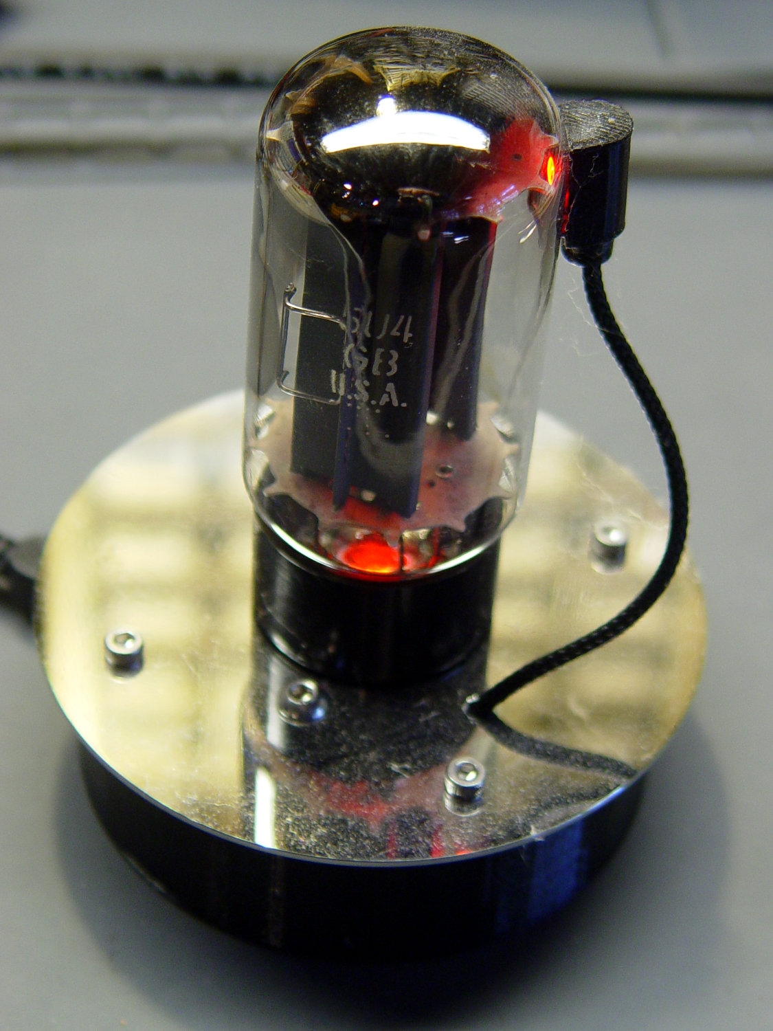
Because I’d be crazy to replace it with another likely-to-fail WS2812, I had to remove both of them before installing SK6812 RGBW LEDs and updating the Arduino Nano.
Unfortunately, I did a really good job of bonding the side light to the tube with epoxy:
Failed WS2812 – 5U4GB broken glass
The last tube manufacturing step involved flashing the getter onto the tube envelope, so as to remove the last vestige of air. Admitting air oxidizes the getter:
Gently pry the metal cover outward to clear the latches along the sides:
DSC-F717 – Memory Stick socket cover latches
The cover remains held in place by two tabs inside the holes on either side of the Memory Stick contacts, one of which is already free in the previous photo:
DSC-F717 – Memory Stick socket – bottom
The small spring on the left ejects the Memory Stick and will, if suitably provoked, launch itself across the bench. Be prepared!
Use a pointy instrument to ease those tabs away from their latches and pop the top:
DSC-F717 – opened Memory Stick socket
I cleaned the contacts, not that they appeared particularly filthy, gently bent them upward by three micro-smidgens to apply a bit more pressure to the card’s contacts, and reassembled the socket in reverse order.
I put a strip of Kapton tape on the back of the cable termination paddle (shown here during the previous repair) to ensure a snug fit:
DSC-F717 Memory Stick socket – cable entry
Unfortunately, I snapped off a locking tab on one of the ribbon cable connections to the main board:
DSC-F717 – broken cable clamp
The cable threads through the middle of the clamp, which then slides into the socket and applies pressure to the contacts through the cable: no clamp, no pressure, no good.
For lack of anything smarter, I tamped the clamp into the socket and applied a strip of Kapton tape to maintain everything in more-or-less the right position:
DSC-F717 – tape-anchored cable
Definitely unpretty, but better than nothing. While I was in there, I reinforced the other connections with similar clamps.
Reassemble the camera in reverse order and it’s all good:
DSC-F717 – repaired – first image
It probably won’t last another decade, but ya never know …
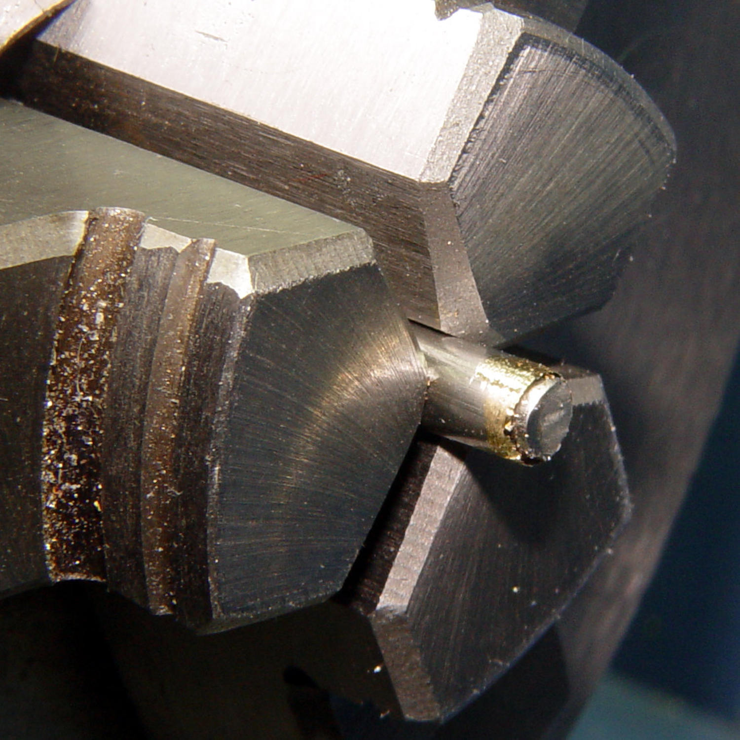
After considerable evaluation, the Customer decided the shoelaces were still too long and said the hex-crimped ferrules were entirely too rough and tended to snag on things. This time, I prepared the ferrules by chucking them in the lathe:
Ferrule – original flange
The steel rod inside the ferrule encourages it to remain round and not collapse while I’m filing off the flange that normally holds the plastic strain-relief doodad:
Ferrule – reshaped flange
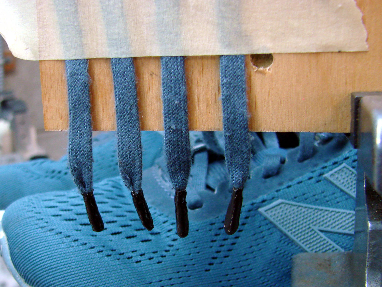
I snipped another half inch off each end of the laces and crimped on the prepared ferrules:
Shoelace ferrule aglets
Which were definitely too jaggy, so they now sport an epoxy coat:
Ferrule aglets – epoxy coat
Alas, JB Kwik epoxy has a pot life measured in minutes, so the last ferrule looks a bit lumpy. They seem to work fine and the Customer is happy with the results.
Memo to Self: Next time, dunk the ferrules in a pot of slow-curing JB Weld and let them drain overnight.
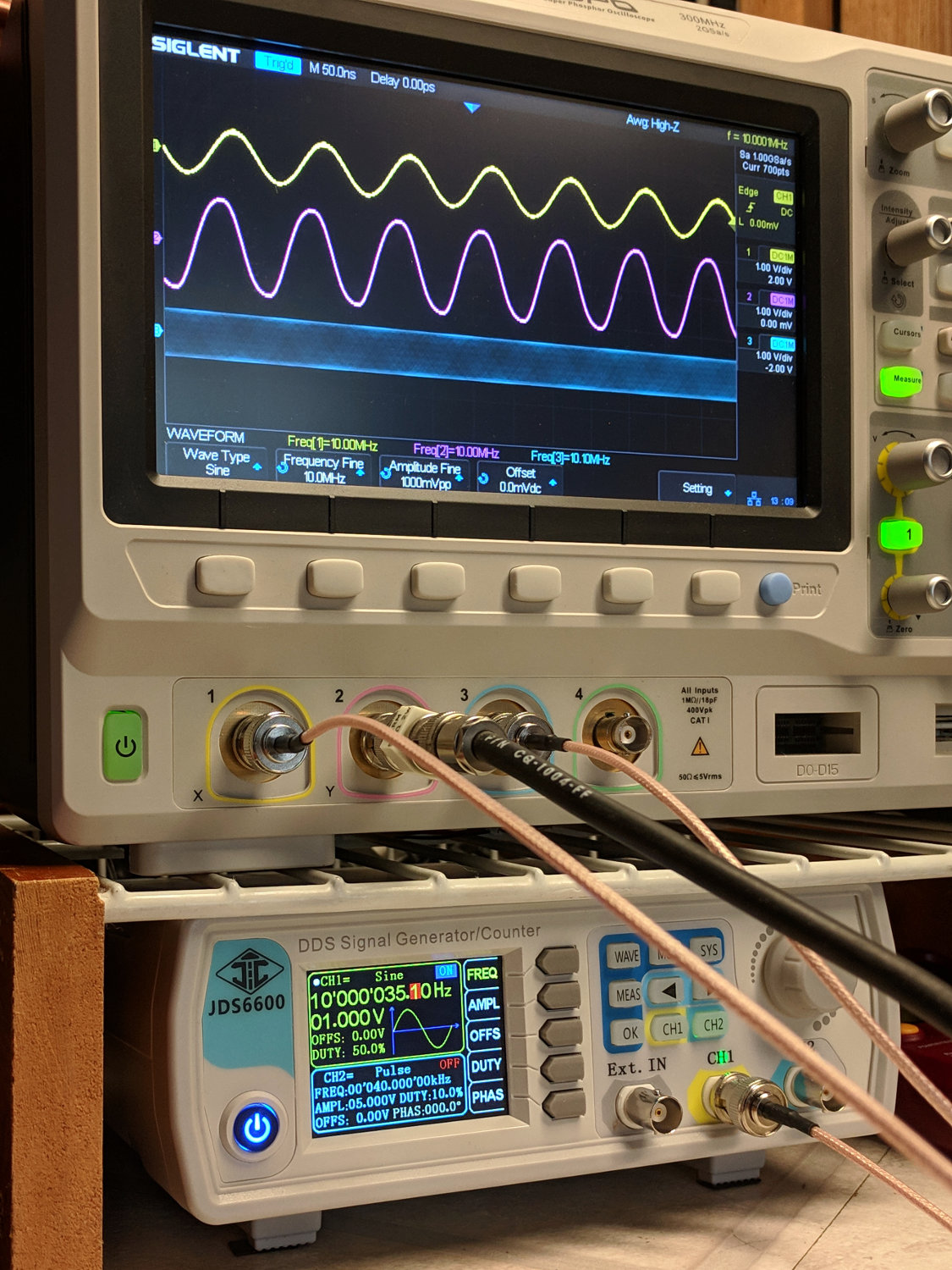
An RD JDS6600 Signal Generator recently arrived from around the curve of the horizon, leading me to measure its warmup time:
RDS6600 Signal Generator – Warmup plot
Looks like it’s good to go after maybe 90 minutes and, after much longer, it settles to 10 MHz +36 Hz, for a correction factor of 0.9999964 on those days when you’re being really fussy.
The need for frequencies accurate to better than 4 ppm doesn’t happen very often around here, but it’s best to be prepared. It’s amazing what you can get for under $100 these days …
RDS6600 Signal Generator vs. Z3801 GPS Frequency Standard
Basically, trigger the scope on either trace, crank the JDS6600 frequency in 1 Hz, then 0.1 Hz steps, until the traces stop crawling past each other, and you’re done.
It’s worth noting you (well, I) must crank eleven 0.01 Hz steps to change the output frequency by about 0.1 Hz around 10 MHz, suggesting the actual frequency steps are on the order of 0.1 Hz, no matter what the display resolution may lead you to think.
The RDS6600 main PCB (Rev 15) sports a 24 MHz oscillator close to the Lattice FPGA:
The bottom trace is the scope’s internal function generator, also set to 10 MHz. Zero-beating the JDS6600 against the scope’s output produces a similar result:
IMG_20190312_130925 – RDS6600 vs SDS2304X frequencies
The scope’s function generator actually runs at (9.999964 MHz) × (0.9999964) = 9.999928 MHz, a whopping 72 ppm low. The on-screen frequency measurements don’t have enough resolution to show the offset, nor to zero-beat it with the Z3801 input, so it’s as good as it needs to be.
The Z3801’s double-oven oscillator takes a few days to settle from a cold start, so this wasn’t an impulsive measurement. Having the power drop midway through the process didn’t help, either, but it’s March in the Northeast and one gets occasional blizzards with no additional charge.