Ed Nisley's Blog: Shop notes, electronics, firmware, machinery, 3D printing, laser cuttery, and curiosities. Contents: 100% human thinking, 0% AI slop.
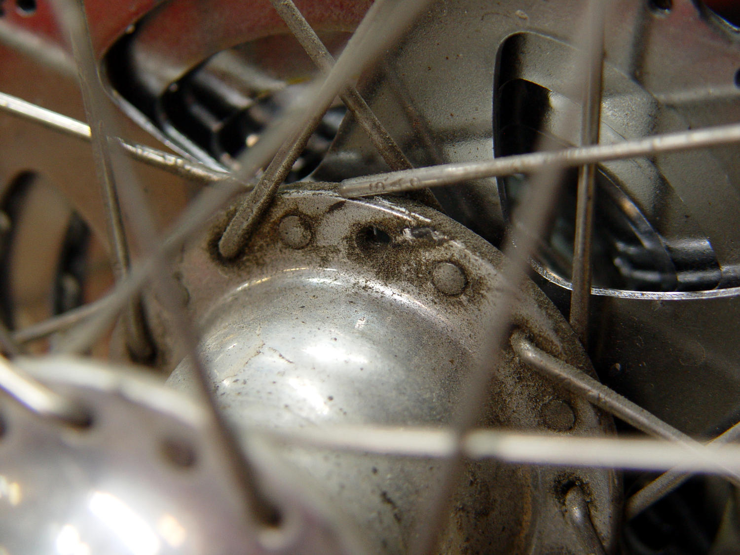
I’d noticed some brake drag on our last few rides, but forgot to check until I saw the rim wobble while extracting images from the rear camera.
It’s a lot easier to fix in the Basement Shop than on the road. After nigh onto a decade since replacing the last broken spoke, perhaps this is a harbinger of doom to come.
Memo to Self: spoke tension is now 20-ish on the drive side, 15-ish on the left.
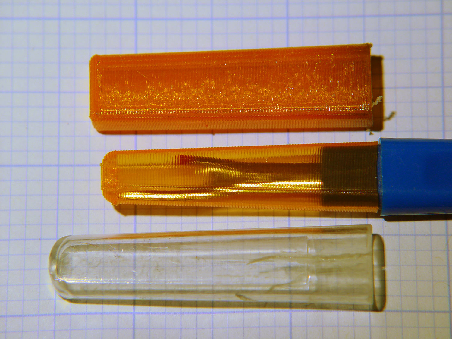
The cover for Mary’s favorite seam ripper cracked long ago, has been repaired several times, and now needs a replacement:
Seam Ripper cover – overview
The first pass (at the top) matched the interior and exterior shapes, but was entirely too rigid. Unlike the Clover seam ripper, the handle has too much taper for a thick-walled piece of plastic.
The flexy thinwall cover on the ripper comes from a model of the interior shape:
Seam Ripper Cover – handle model
It’s not conspicuously tapered, but OpenSCAD’s perspective view makes the taper hard to see. The wedge on top helps the slicer bridge the opening; it’s not perfect, just close enough to work.
A similar model of the outer surface is one thread width wider on all sides, so subtracting the handle model from the interior produces a single-thread shell with a wedge-shaped interior invisible in this Slic3r preview:
Seam Ripper Cover – exterior – Slic3r preview
The brim around the bottom improves platform griptivity. The rounded top (because pretty) precludes building it upside-down, but if you could tolerate a square-ish top, that’s the way to go.
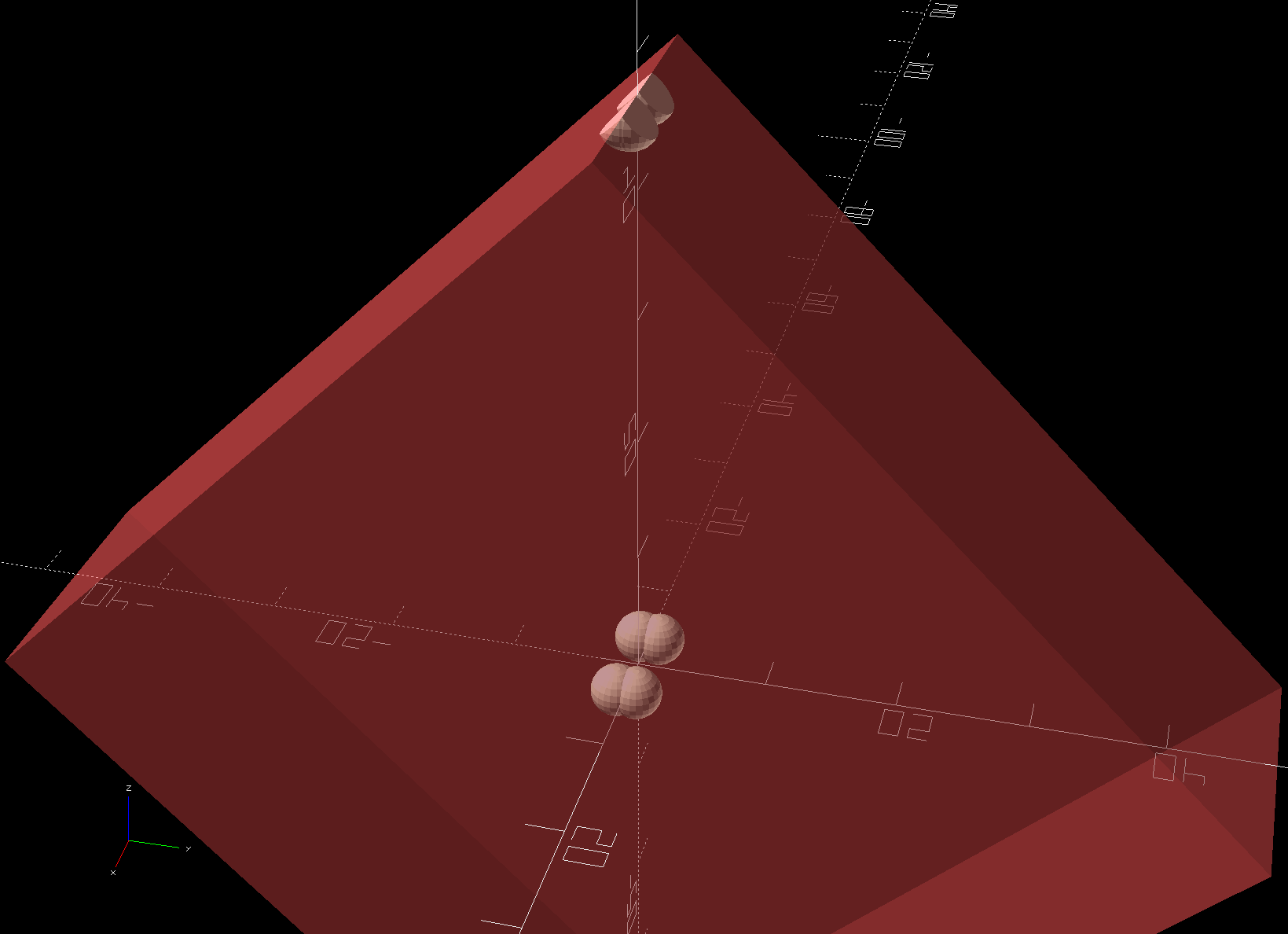
Both models consist of hulls around eight strategically placed spheres, with the wedge on the top of the handle due to the intersection of the hull and a suitable cube. This view shows the situation without the hull:
Seam Ripper Cover – handle model – cube intersection
The spheres overlap, with the top set barely distinguishable, to produce the proper taper. I measured the handle and cover’s wall thicknesses, then guesstimated the cover’s interior dimensions from its outer size.
The handle’s spheres have a radius matching its curvature. The cover’s spheres have a radius exactly one thread width larger, so the difference produces the one-thread-wide shell.
Came out pretty nicely, if I do say so myself: the cover seats fully with an easy push-on fit and stays firmly in place. Best of all, should it get lost (despite the retina-burn orange PETG plastic), I can make another with nearly zero effort.
The Basement Laboratory remains winter-cool, so I taped a paper shield over the platform as insulation from the fan cooling the PETG:
Seam Ripper Cover – platform insulation
The shield goes on after the nozzle finishes the first layer. The masking tape adhesive turned into loathesome goo and required acetone to get it off the platform; fortunately, the borosilicate glass didn’t mind.
This file contains hidden or bidirectional Unicode text that may be interpreted or compiled differently than what appears below. To review, open the file in an editor that reveals hidden Unicode characters.
Learn more about bidirectional Unicode characters
Having an ancient flip phone in need of a battery, I ordered a Kyocera TXBAT10133 battery from eBay. Described as “new” (which, according to the Ebay listing, means “New: A brand-new, unused, unopened, undamaged item in its original packaging”), I was somewhat surprised to see this emerging from the box:
Kyocera TXBAT10133 – not really new
It obviously led a rather hard life before being harvested from somebody else’s obsolete flip phone and is definitely not “new”.
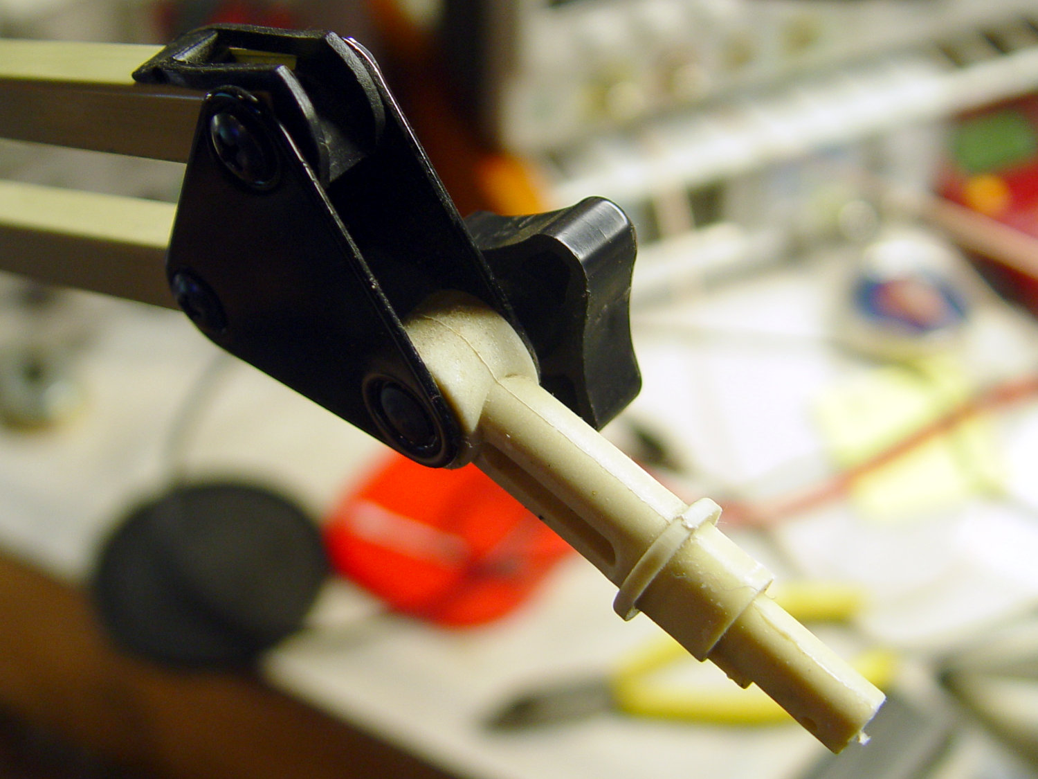
Not yet having a deep emotional attachment to the thing, I set it up for a capacity test:
Kyocera TXBAT10133 – contact clamp
Given a very light 100 mA load, it shows about the same capacity as the original battery in our phone:
Kyocera TXBAT10133 – 2019-03-29
Given the precarious contact arrangement, the glitches near the right end aren’t surprising.
The battery label claims a 900 mA·h rating, so both have nearly their nominal capacity at such a reduced load. In actual use, the phone has a low battery after a few hours of power-on time, far less than when it was new.
The seller promises a replacement. For all I know, there are no genuinely “new” batteries available for these phones.
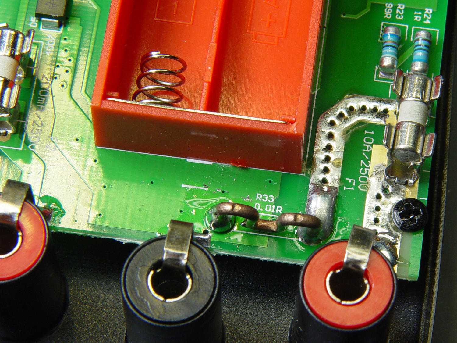
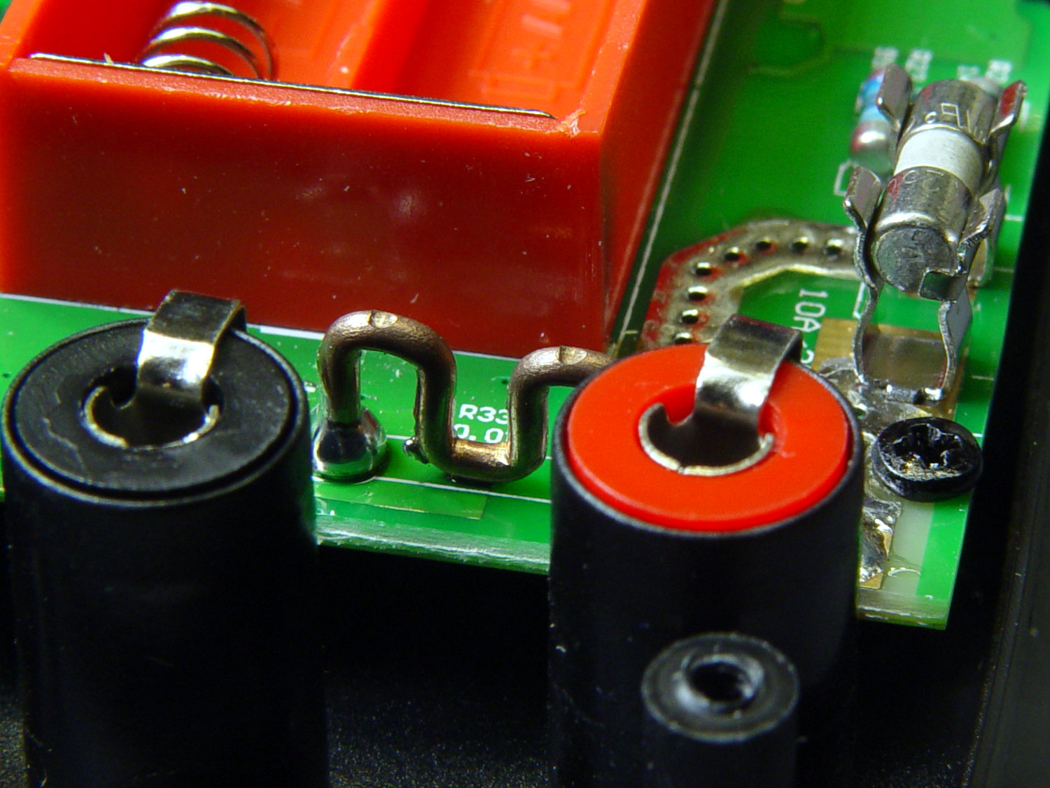
Somewhat to my surprise, Aneng AN8008/AN8009 multimeter PCBS sport what looks like a reasonably accurate current sense resistor on the 10 A input:
AN8009 10 A current shunt – top view
The legend says 0.01R and the conductor doesn’t look quite like pure copper:
AN8009 10 A current shunt – side view
The indentations look like clamp marks from the bending jig, rather than “calibration” notches made while squeezing the wire with diagonal cutters and watching the resistance on another meter.
One might quibble about the overall soldering quality, but one would also be splitting hairs. I doubt the meter leads could withstand 10 A for more than a few seconds, anyhow.
If you buy enough of something, you can buy pretty nearly anything you want, even cheap precision resistors!
Having recently acquired a pair of photo lights and desirous of eliminating some desktop clutter, I decided this ancient incandescent (!) magnifying desk lamp had outlived its usefulness:
Desk Lamp – original magnifiying head
The styrene plastic shell isn’t quite so yellowed in real life, but it’s close.
Stripping off the frippery reveals the tilt stem on the arm:
Desk Lamp – OEM mount arm
The photo lights have a tilt-pan mount intended for a camera’s cold (or hot) shoe, so I conjured an adapter from the vasty digital deep:
Photo Light Bracket for Desk Lamp Arm – solid model
Printing with a brim improved platform griptivity:
Photo Light Bracket for Desk Lamp Arm – Slic3r preview
Fortunately, the photo lights aren’t very heavy and shouldn’t apply too much stress to the layers across the joint between the stem and the cold shoe. Enlarging the stem perpendicular to the shoe probably didn’t make much difference, but it was easy enough.
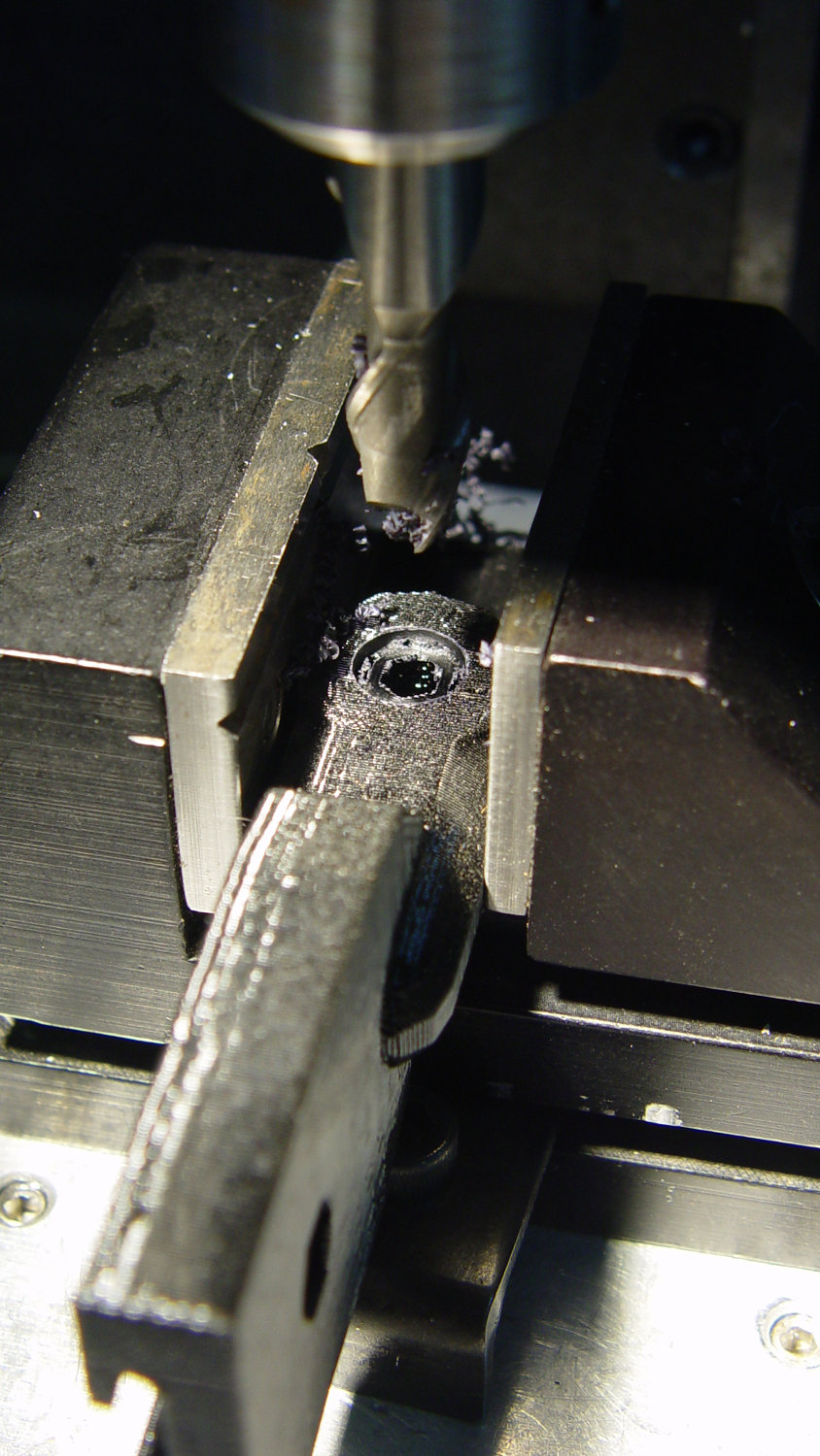
Of course, you (well, I) always forget a detail in the first solid model, so I had to mill recesses around the screw hole to clear the centering bosses in the metal arm plates:
Photo Lamp – bracket recess milling
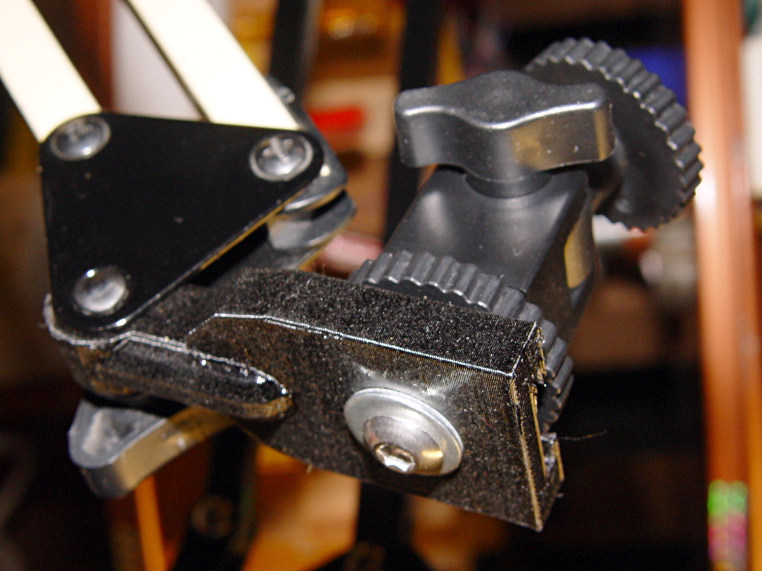
Which let it fit perfectly into the arm:
Desk Lamp – photo lamp mount installed
The grody threads on the upper surface around the end of the slot came from poor bridging across a hexagon, so the new version has a simple and tity flat end. The slot is mostly invisible with the tilt-pan adapter in place, anyway.
There being no need for a quick-disconnect fitting, a 1/4-20 button head screw locks the adapter in place:
Photo Lamp – screw detail
I stripped the line cord from inside the arm struts and zip-tied the photo lamp’s wall wart cable to the outside:
Photo Lamp – installed
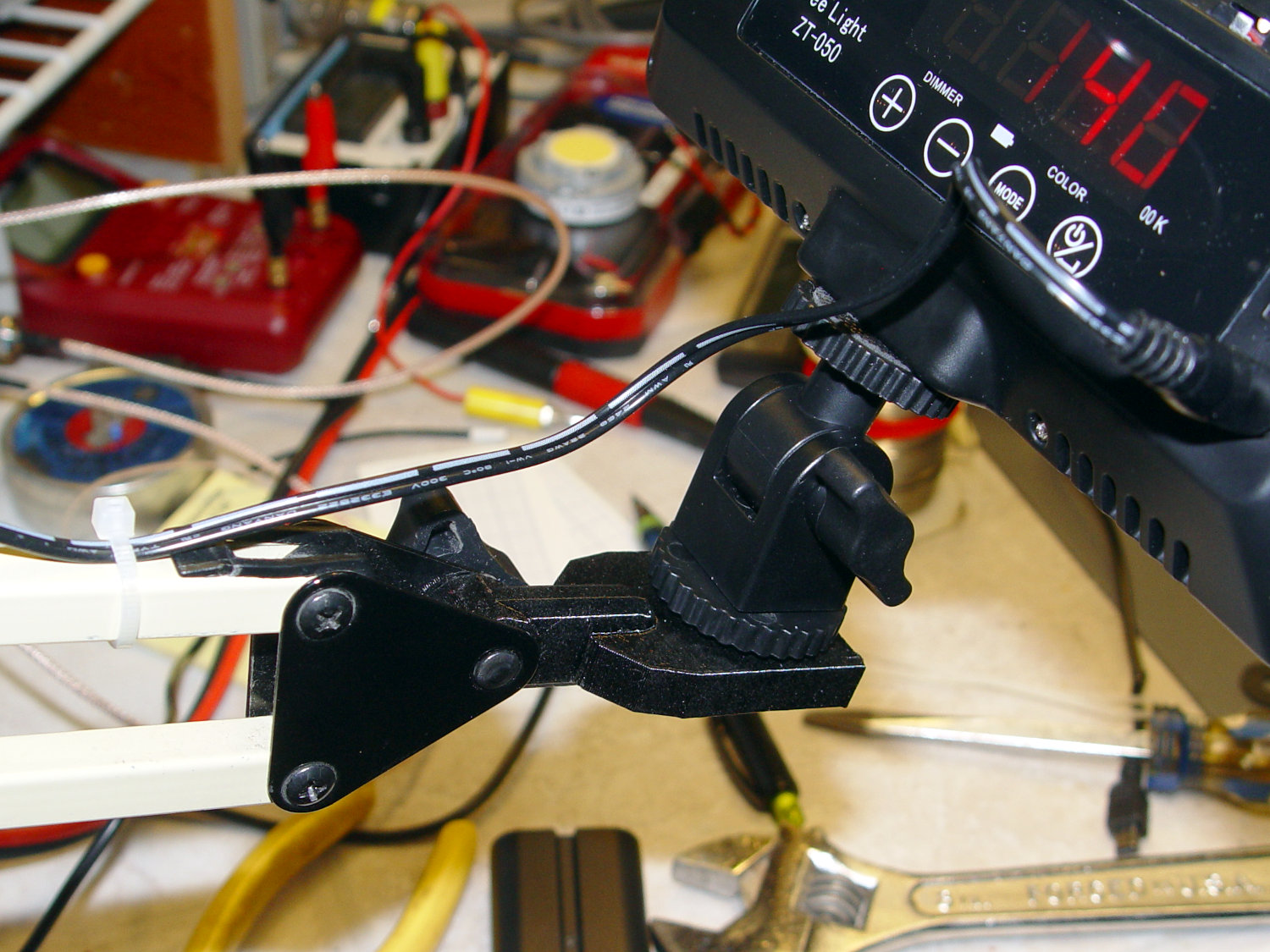
And then It Just Works™:
Photo Lamp – test image
The lens and its retaining clips now live in the Big Box o’ Optical parts, where it may come in handy some day.
This file contains hidden or bidirectional Unicode text that may be interpreted or compiled differently than what appears below. To review, open the file in an editor that reveals hidden Unicode characters.
Learn more about bidirectional Unicode characters
We’d been eating a “healthy” high-carb / low-fat diet, which produced the more-or-less expected 1 lb/yr weight gain over the course of three decades. Given that we eat about 106 Cal/yr, being off by a mere 0.3% seemed fixable, but we were always hungry while trying to cut out calories.
In April 2016, we decided our tummies had come between us, so we switched to a mostly ketogenic diet (clicky for more dots):
Weight Chart 2016 – Ed
Having a Master Gardener in the family complicates dietary choices along the ketogenic axis, but Mary raised more green-and-leafy veggies, less squash-and-corn, and we keto-ized our meals reasonably well. Moderation in all things works fine for us, so losing 25 pounds at about 1 lb/week wasn’t particularly stressful.
Continuing through 2017, you can see how regular bike riding season affects winter bloat:
Weight Chart 2017 – Ed
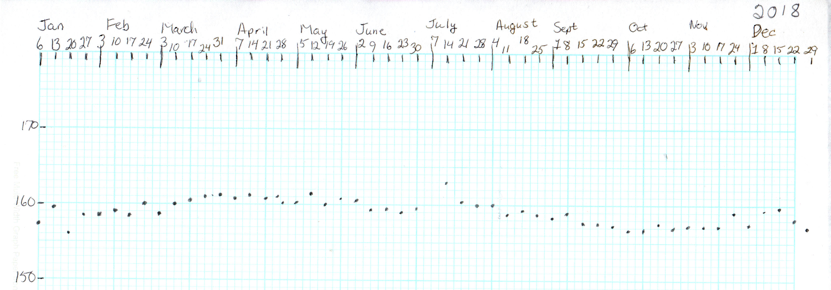
Our cycling vacation in July 2018 produced a blip, but the rest of the riding season worked as expected:
Weight Chart 2018 – Ed
It’s straightforward to crash-diet two dozen pounds, but maintaining a more-or-less stable weight for the next two years suggests we’ve gotten the annual calorie count about right. FWIW, my bloodwork numbers sit in the Just Fine range, apart from the somewhat elevated cholesterol level typical of a keto-ized diet.
Starting in late 2018, however, a stressful situation of a non-bloggable nature (at least for a blog such as this) produced an unusually high number of road trips, motel stays, and generally poor dietary choices:
Weight Chart 2019-03 – Ed
The situation now being over, our lives / exercise / diet will return to what passes for normal around here and my goal is to lose another 10% of my current body weight, ending at 150 pounds, by the end of the year. In round numbers, that requires losing half a pound = 1700 Cal/week, 250 Cal/day. Not power-noshing an ounce or two of nuts a day should do the trick.
If it makes you feel more science-y, you can use the NIH Body Weight Planner, but it produces about the same answer: knock off 300 Cal to lose weight, 250 Cal to maintain it, at essentially the same exercise level as before.
We’ve been recording our weights as dots on graph paper every Saturday evening for the last four decades, so I know for a fact I averaged 148 pounds when I wore a younger man’s clothes. I’ll re-post the 2019 chart, adding four dots every month, during the rest of the year.
I know no more than you do about the situation, but I’d lay long, long odds Hannaford created the poster with a more recent version of Microsoft Word (or whatever) than the recipient organization has available, making the file essentially read-only.
Not casting shade on ’em; sometimes, you do what you gotta do.
FWIW, I’d expect LibreOffice and any Microsoft Word version other than the exact one used to create the poster to mangle the formatting differently. Been there, done that.