Another month of data from all those Polydryer boxes:
| 7 Oct 2025 | 8 Oct | |||
| Filament | %RH | Weight – g | Wt gain – g | %RH |
| PETG White | 28 | 26.6 | 1.6 | 19 |
| PETG Black | 25 | 26.6 | 1.6 | 20 |
| PETG Orange | 29 | 26.6 | 1.6 | 21 |
| PETG Blue | 23 | 26.7 | 1.7 | 15 |
| PETG-CF Blue | 26 | 26.6 | 1.6 | 23 |
| PETG-CF Black | 23 | 26.4 | 1.4 | 20 |
| PETG-CF Gray | 30 | 26.5 | 1.5 | 26 |
| TPU | 28 | 26.3 | 1.3 | 27 |
| Empty 1 → White | 35 | 26.7 | 1.7 | 37 |
| Empty 2 | 36 | 27.1 | 2.1 | 24 |
The “PETG White” spool in the top line is nearly empty, so I loaded a new spool into the “Empty 1” box.
The “Empty 1” 35% value on 7 Oct matches the other empty box, the desiccant having pulled the humidity down from the 51% basement level. The weight of the water pulled out seems low compared to “Empty 2”, as they both started with a fresh batch of basement air while changing the desiccant in September.
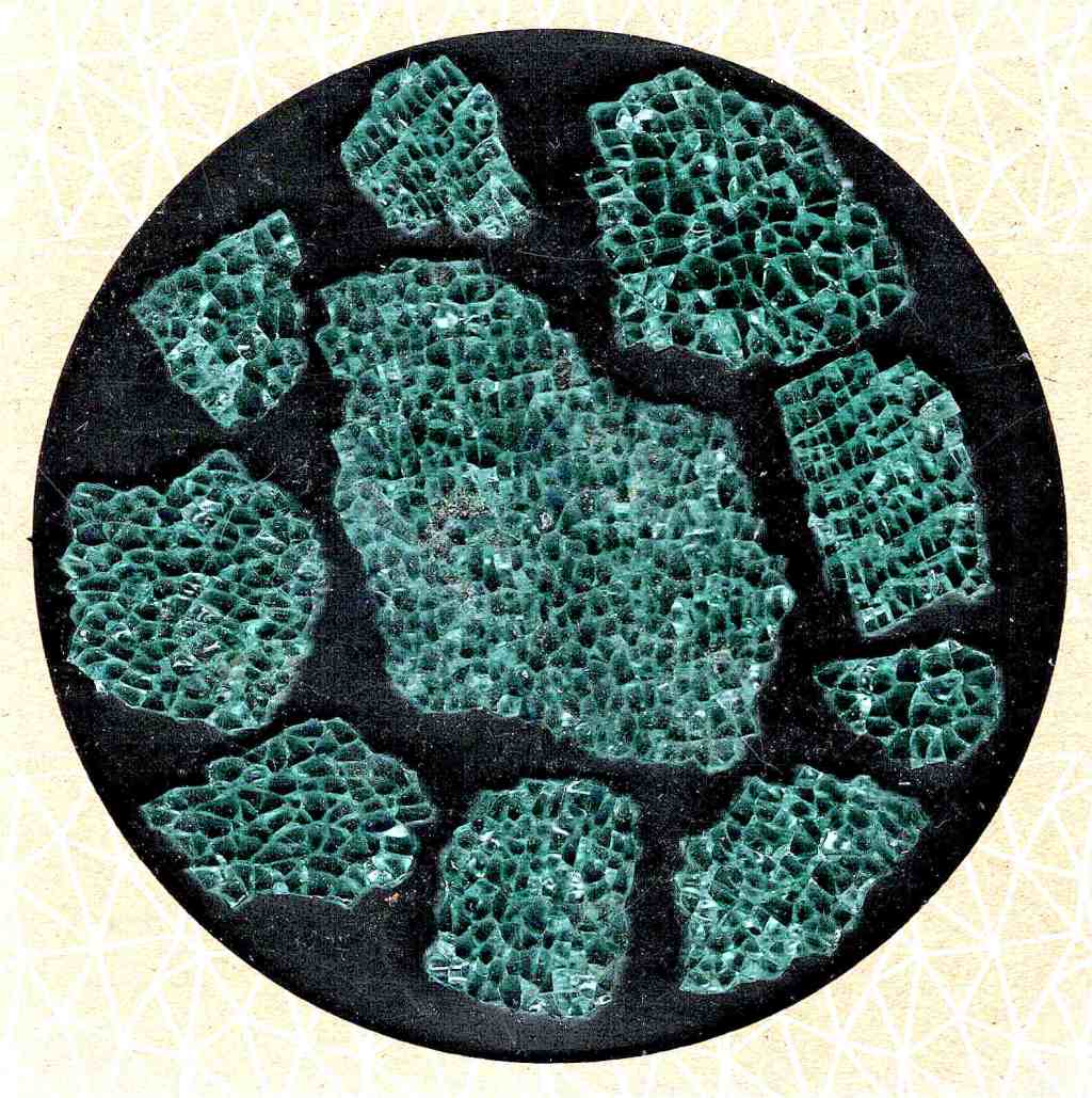
They’re again filled with 25 g of alumina beads, although I’m beginning to think silica gel does a better job.
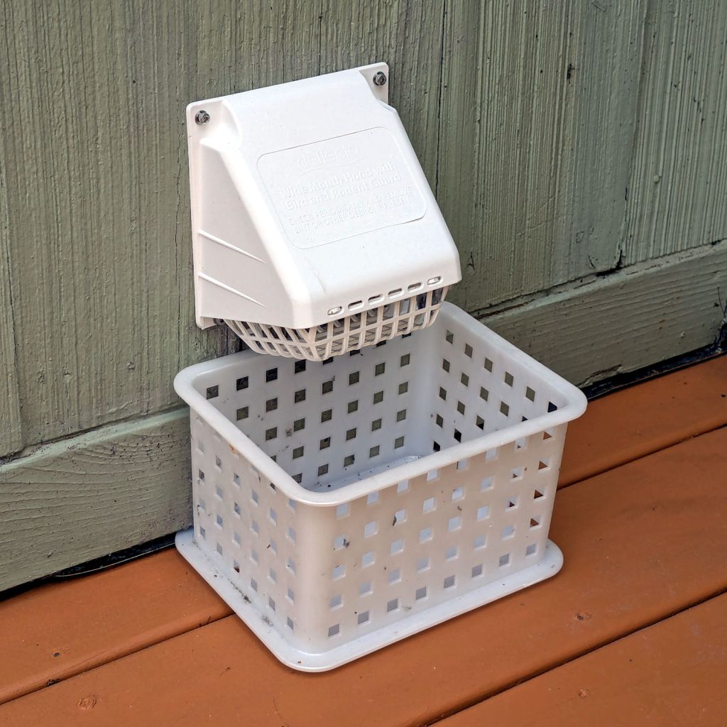
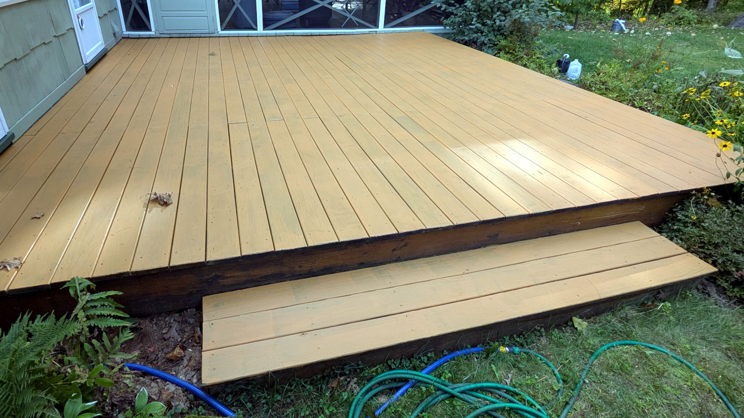
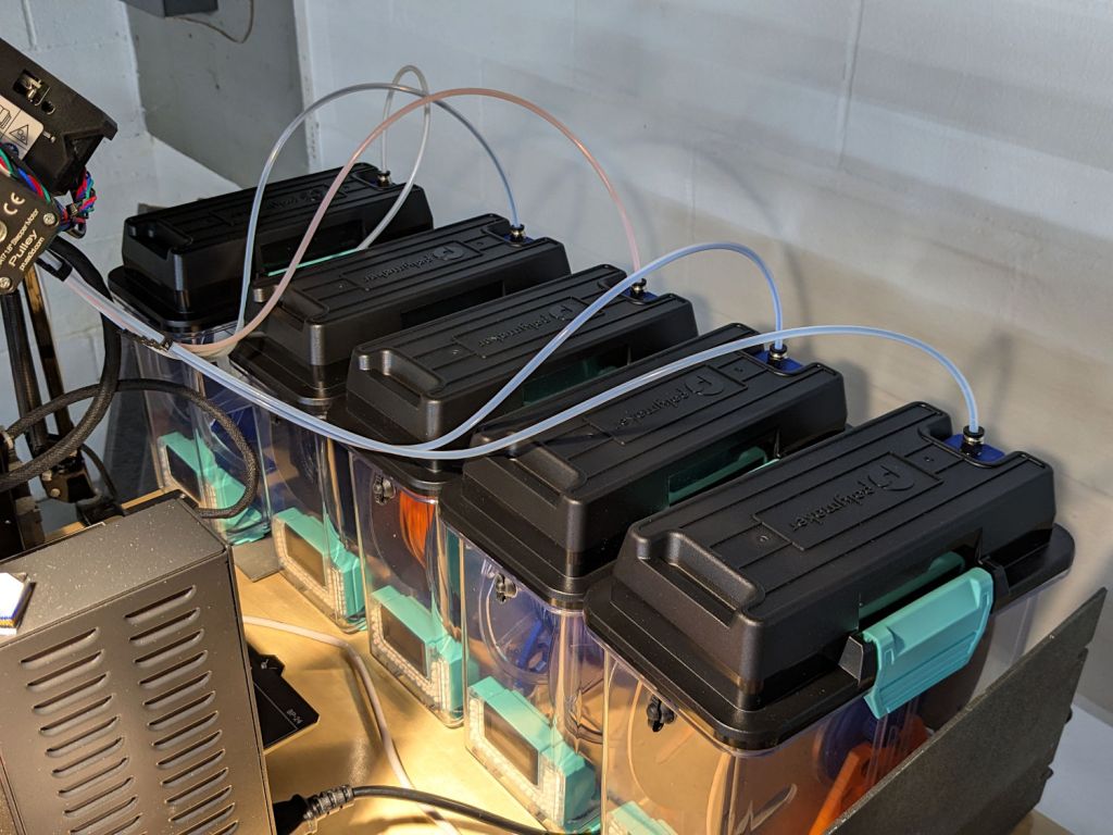
A picture of the boxes, thus avoiding WordPress reminding me pictures improve SEO: