Ed Nisley's Blog: Shop notes, electronics, firmware, machinery, 3D printing, laser cuttery, and curiosities. Contents: 100% human thinking, 0% AI slop.
A sheet of craft adhesive holds them together; stick a generous rectangle of adhesive on the cork, then cut them at the same time. However, given the irregular perimeter, it’s basically impossible (for me, anyway) to align the cork + adhesive with the printed frame.
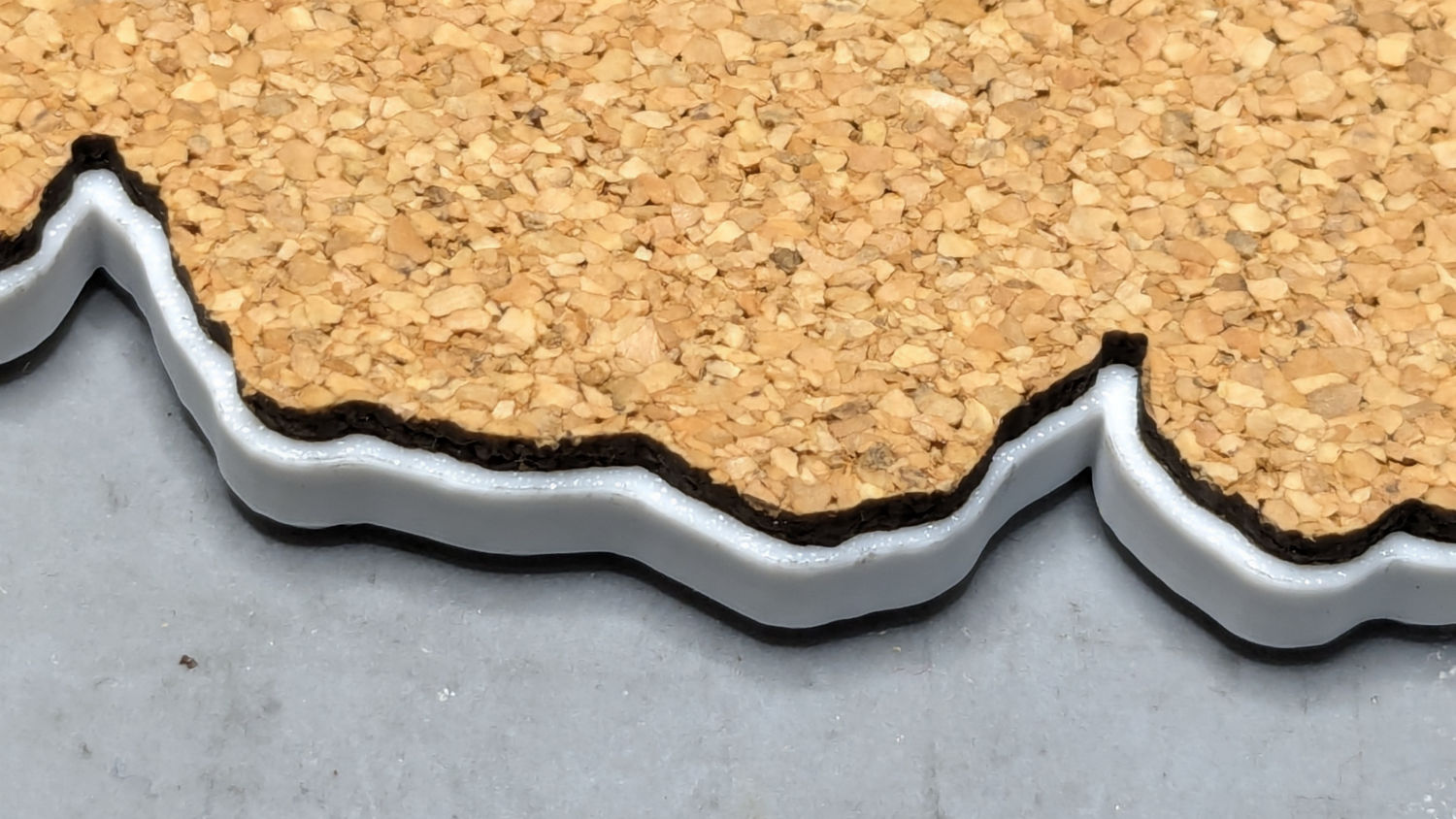
A single-use fixture made from corrugated cardboard make that task trivially easy:
Printed Coaster – cork alignment fixture – detail
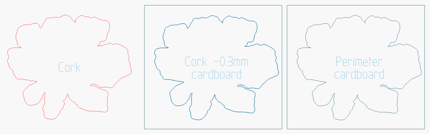
The LightBurn layout shows the cork layer and the two fixture pieces:
The cork shape is offset 0.5 mm inward from the Perimeter shape, but I found offsetting the cardboard cut by only 0.3 mm inward produced a snug fit around the cork. The other piece of cardboard gets cut with the exact Perimeter shape and no offset, with the laser kerf providing just enough clearance for a very snug fit on the printed shape.
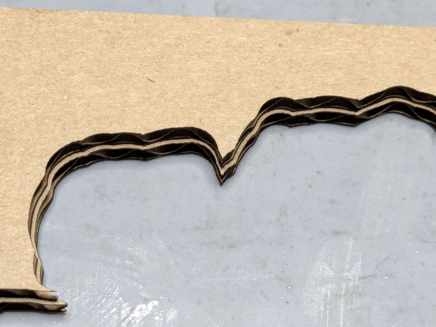
Align the two pieces of cardboard by eye to match their inner shapes as shown in the picture, tape them together, and the fixture is ready. In principle, the outer edges should exactly coincide: Trust, but verify.
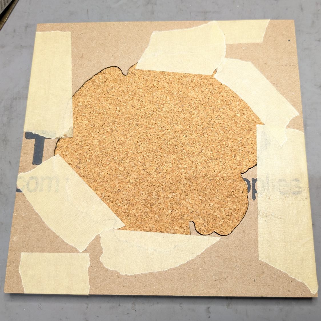
Peel off the craft adhesive paper and put the cork in the bottom of the fixture. The cork comes off a roll and really wants to roll up again, making the masking tape holding it flat mandatory:
Printed Coasters – cork alignment template
Yes, that’s a different coaster.
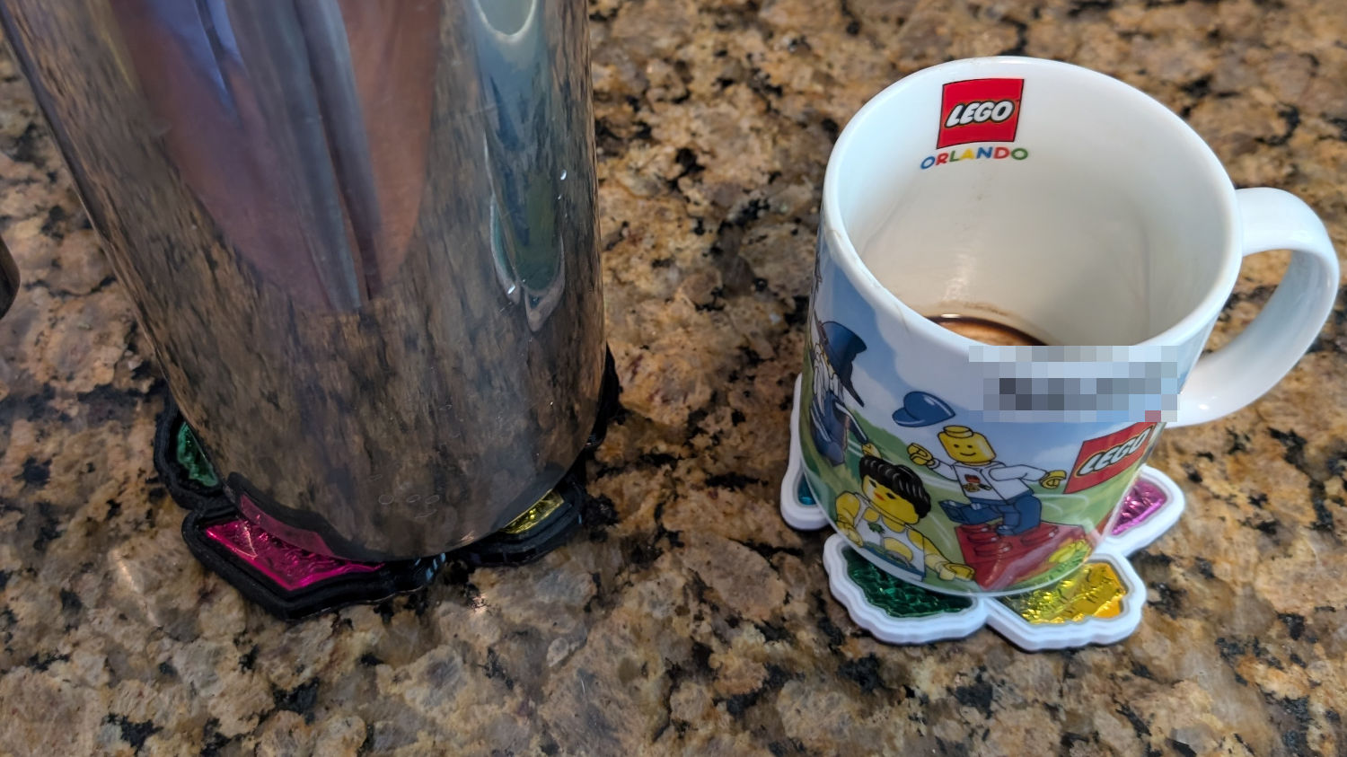
Flip the fixture over, drop the coaster in place, press firmly together, peel the tape, and pull out the finished coaster:
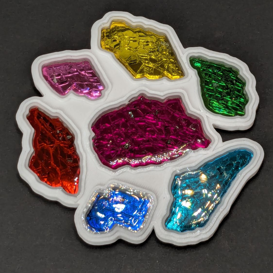
Printed Coasters – white PETG finished
The fixture goes in the recycling bin, as those fragments will never pass this way again.
Create the perimeter path as an offset around all the fragments in LightBurn
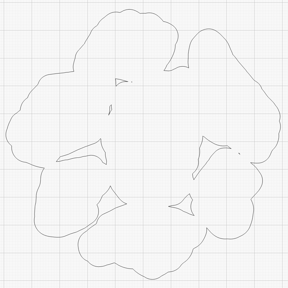
Because the fragments have irregular shapes and spacing, creating the perimeter path may also produce small snippets of orphaned geometry which must be manually selected and deleted. I also edit the path to remove very narrow channels between adjacent fragments.
Which is why you can’t generate that path automatically:
Printed Coaster Layout – 100 mm Set G – LightBurn perimeter geometry
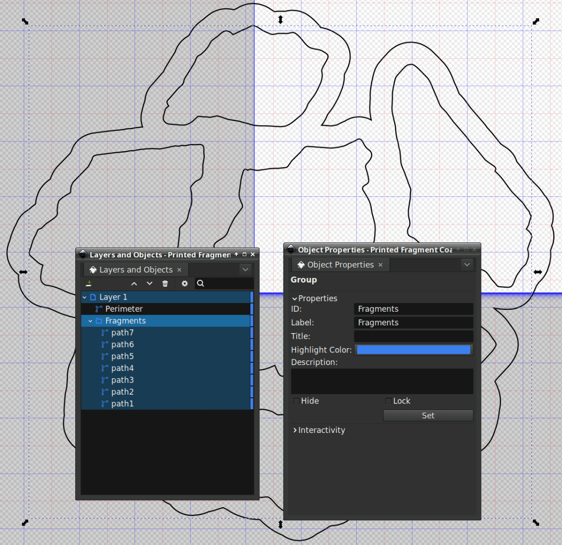
Because LightBurn doesn’t have the ability to name the various paths, the next step requires Inkscape. After importing the LightBurn paths saved as an SVG, group all the fragments and name the group Fragments, then name the perimeter path Perimeter:
Printed Coaster Layout – 100 mm Set G – Inkscape layer and IDs
Inkscape still crashes unpredictably while doing what seems to be a simple process, which may be due to the tremendous number of points in the hand-traced fragment outlines. Unfortunately, simplifying the curves in either LightBurn or Inkscape tends to round off the extreme points and increases the likelihood of the fragment not fitting into its recess.
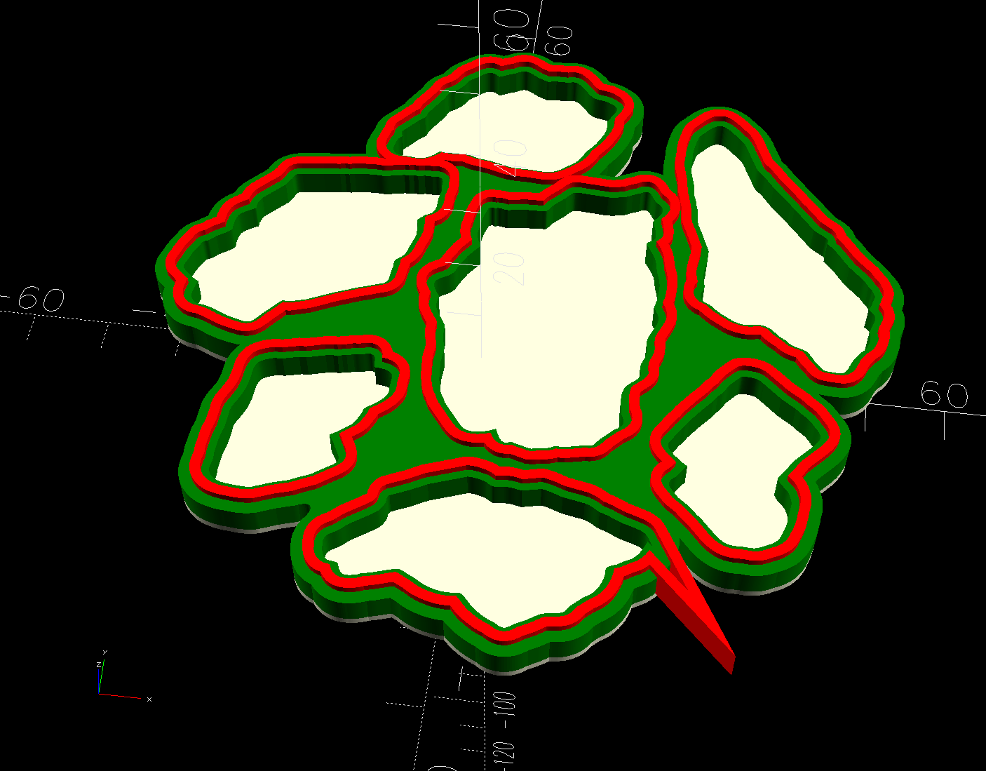
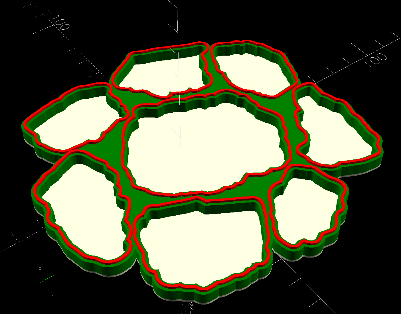
OpenSCAD generates all the other features in the solid model with paths plucked from that file:
include <BOSL2/std.scad>

fn = "Printed Fragment Coaster - 100 mm Set G - Inkscape paths.svg";

FragmentThick = 3.8;

BaseThick = 1.0;
RimHeight = 1.0;

union() {

  linear_extrude(h=BaseThick)
    import(fn,id="Perimeter");

   color("Green")
  up(BaseThick)
    linear_extrude(h=FragmentThick)
      difference() {
        import(fn,id="Perimeter");
        offset(delta=0.2)
          import(fn,id="Fragments");
      }

  color("Red")
  up(BaseThick)
    linear_extrude(h=FragmentThick + RimHeight)
      difference() {
        offset(delta=2.5)
          import(fn,id="Fragments");
        offset(delta=1.2)
          import(fn,id="Fragments");
      }


}
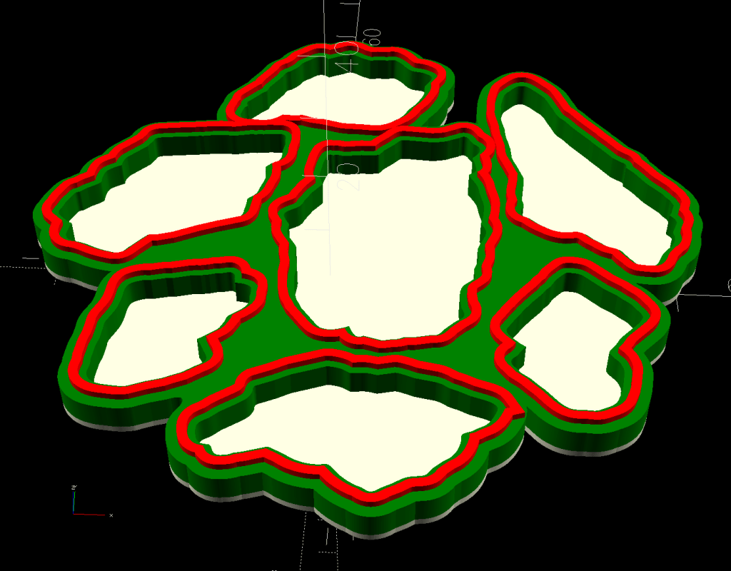
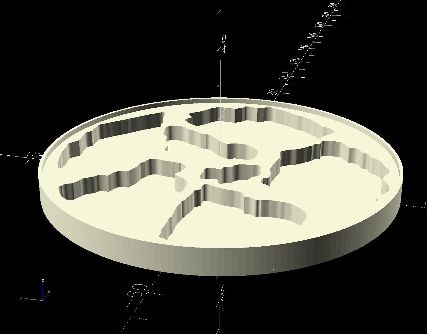
The Perimeter path defines the overall shape of the coaster as a 1.0 mm thick slab, visible as the white-ish line around the edge and at the bottom of all the fragment recesses.
Atop that, the green shape is the same Perimeter shape, with the Fragment shapes removed after the offset() operation enlarges them by 0.2 mm to ensure enough clearance.
Finally, the red walls containing the epoxy above each fragment are 1.3 mm wide, the difference of the two offset() operations applied to the Fragments.
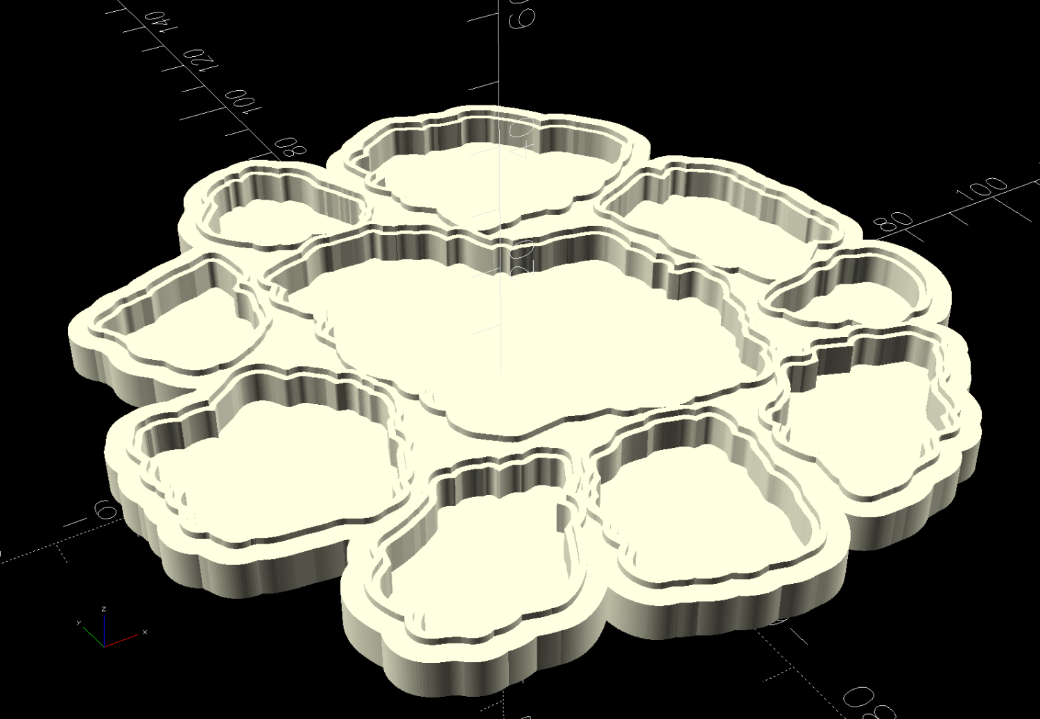
Because the outer edge of the wall is 2.5 mm away from the edge of its fragment:
The Perimeter path must be offset at least 2.5 mm from the Fragments in LightBurn. I used 4.0 mm to produce a small lip around the outside edge of the coaster.
The fragment shapes must be placed at least 5.0 mm apart to prevent the walls from overlapping. I set Deepnest to exactly 5.0 mm spacing, but you can see a few places where the fragments come too close together. I think this happens due to an approximation deepnest uses while rotating the paths, but it may be better to manually adjust the errant fragments than increase the average space.
While this still requires manually tracing the glass fragments and fiddling a bit with Inkscape, the overall process isn’t nearly as burdensome as getting all the offsets correct every time.
However, some oddities remain. OpenSCAD produced this result during the first pass through the process for this coaster:
Printed Coaster Layout – 100 mm Set G – spurious point
As far as I can tell, the spurious point came from a numeric effect, because telling Inkscape to store only five decimal places in the SVG file reduced the spike to the small bump seen in the first picture. I cannot replicate that effect using the same files and have no explanation.
This should have been trivially easy and turned into a nightmare.
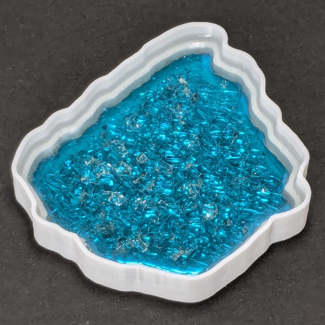
The problem to be solved is generating paths around fragments for the various recesses / reflectors / lips / rims / whatever. This clutter collector was a test piece:
Smashed Glass Clutter Collector – overview
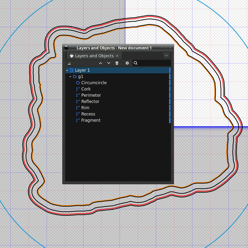
The corresponding paths:
Printed Clutter Collector – Inkscape layers
Which was how I convinced myself I didn’t need all those paths to make the thing, but that’s why it’s a test piece.
Anyhow, Inkscape has a remarkably complex and fiddly way of generating precise offsets:
Select a path
Hit Ctrl-J to create a Dynamic Offset path
Drag the offset path away from the original in any direction for any distance
Hit Ctrl-Shift-x to fire up the XML editor (!)
Change the offset path’s inkscape:radius property to the desired offset
During the course of working that out, I discovered Inkscape 1.4.2 is incredibly crashy when creating and dealing with offsets, to the point that I simply gave up trying to do that.
LightBurn has no trouble creating a path at a specific offset from another path and can export the result as an SVG file. You then use Inkscape to set the path IDs so that OpenSCAD can import them by name for a specific use. Although Inkscape isn’t entirely stable doing even that seemingly trivial task, it’s usable.
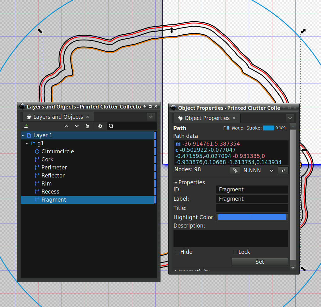
For reasons I do not profess to understand, setting the name of a path sometimes does not set its ID property, which is required by OpenSCAD to extract it from the SVG file. Instead, you must verify / set the ID using the path’s Object Properties window:
Save that, import it into PrusaSlicer, pick the filament, and print it out.
While the printer buzzes away, use LightBurn to cut a shiny blue metallized paper reflector and a cork base using the appropriate paths; presumably you set those paths to LightBurn layers corresponding to the various materials. The Inkscape file has those paths with their names, because … why not?
To assemble:
Cover the bottom of the recess with epoxy
Squish the reflector in place with epoxy oozing around it on all sides
Cover the reflector with epoxy
Squish the fragment atop the reflector with epoxy oozing around it on all sides
Fill the recess level with the lip inside the perimeter wall
Pop bubbles as needed
When it’s cured, stick the cork sheet on the bottom
Note that the OpenSCAD program uses the path geometry without question, so it’s your responsibility to create them with the proper offsets and names.
While all of that to-ing and fro-ing works, in the sense that I did make a rather nice clutter collector, it’s entirely too complicated and fiddly to be useful. Instead, I can now generate a coaster from just the fragment outlines and the coaster’s outer perimeter, a straightforward process which requires a bit more explanation.
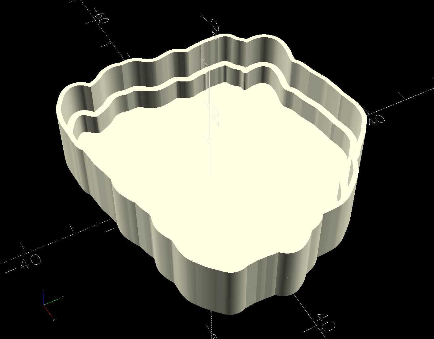
Which worked reasonably well for coasters with a rim around the perimeter to hold in the epoxy covering the entire top surface:
Printed Coaster Layout – solid model
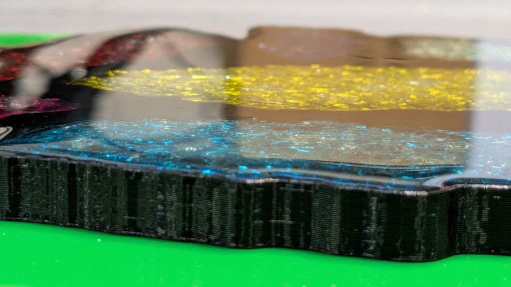
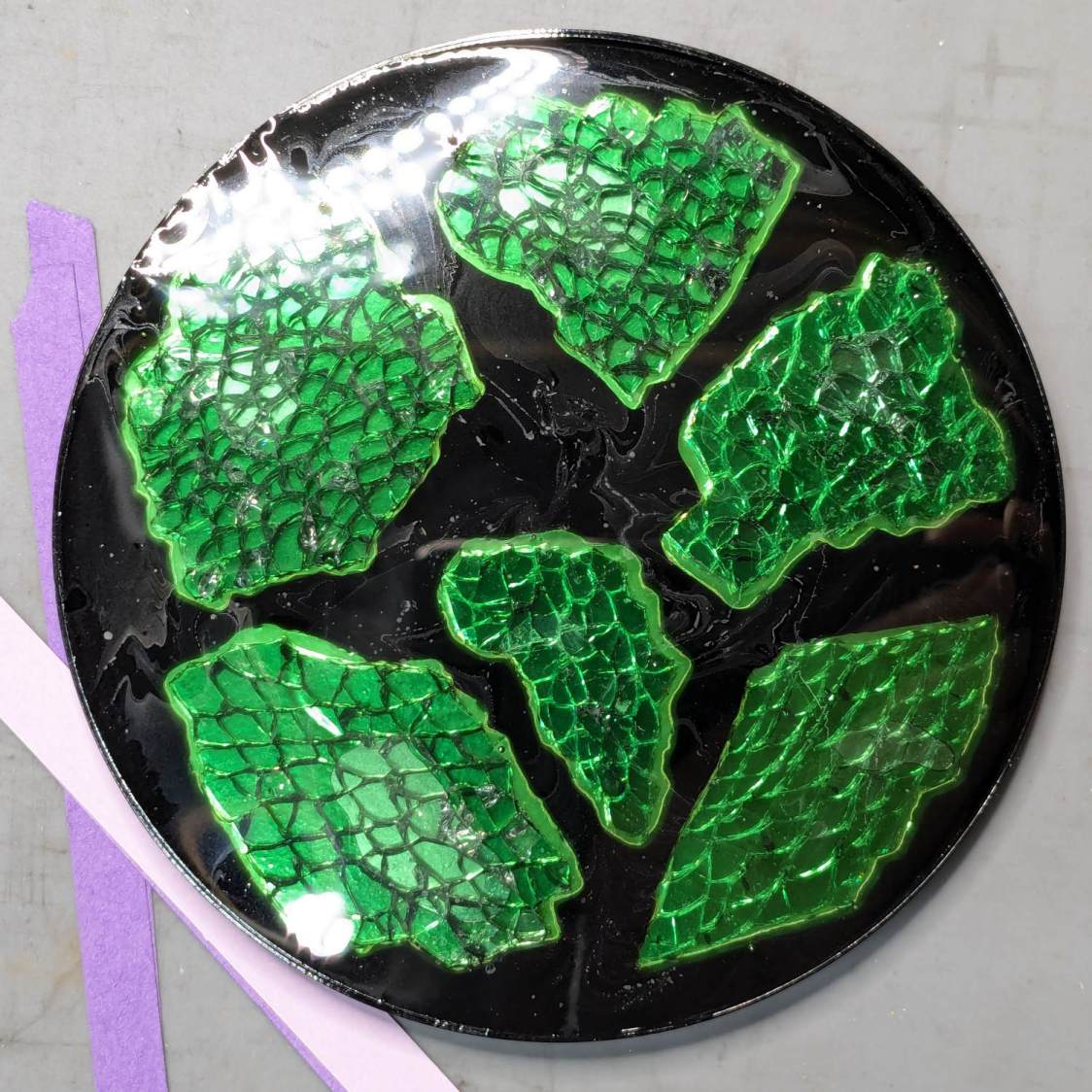
The problem with smooth-top coasters is this:
Printed Coasters – epoxy fill
A slightly sweaty or wet mug can get a firm suction lock on that smooth top, lift the coaster off the table, then drop it into a plate of food.
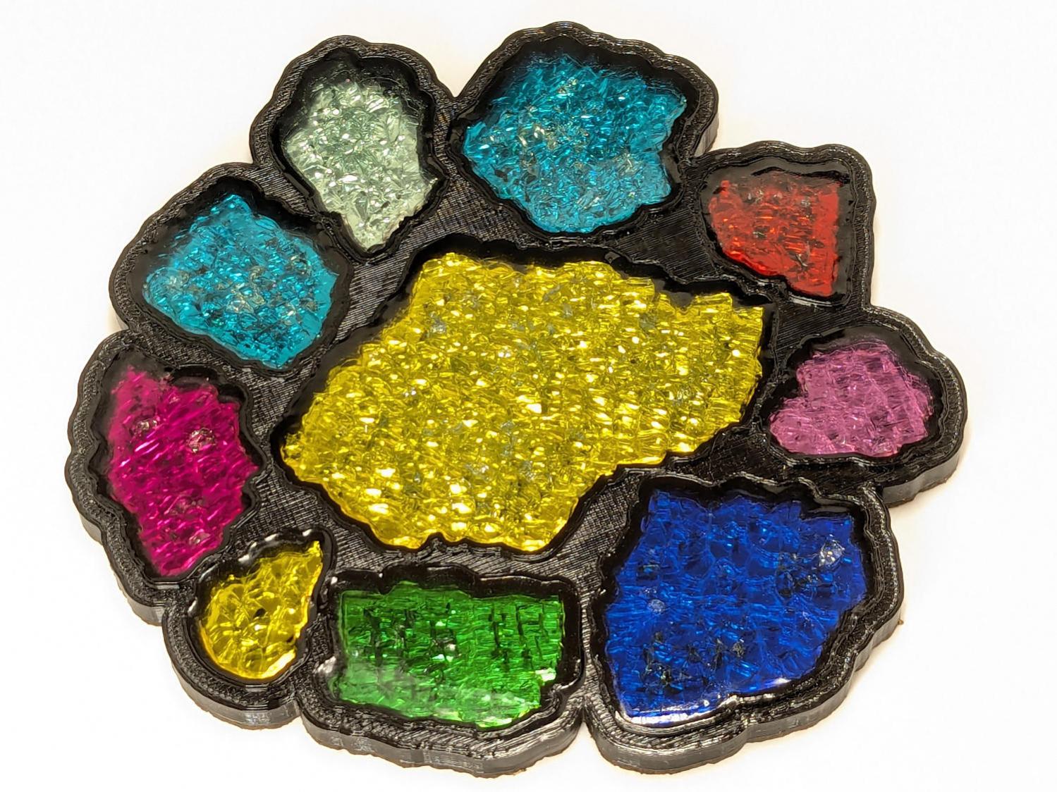
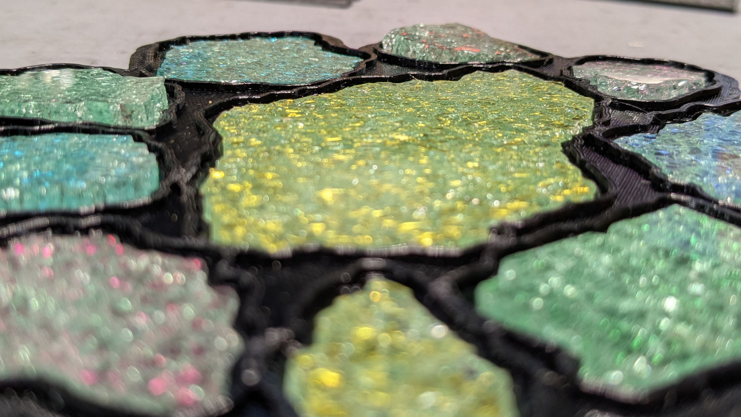
So I put a rim around each fragment to separate the epoxy surfaces and break the suction lock:
Printed Coaster Layout – 5 inch Set B
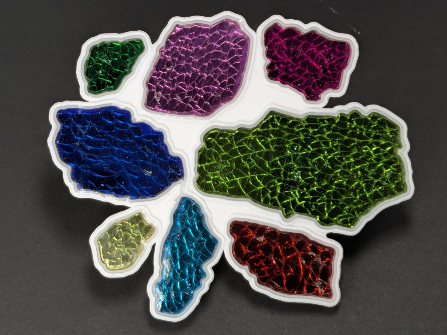
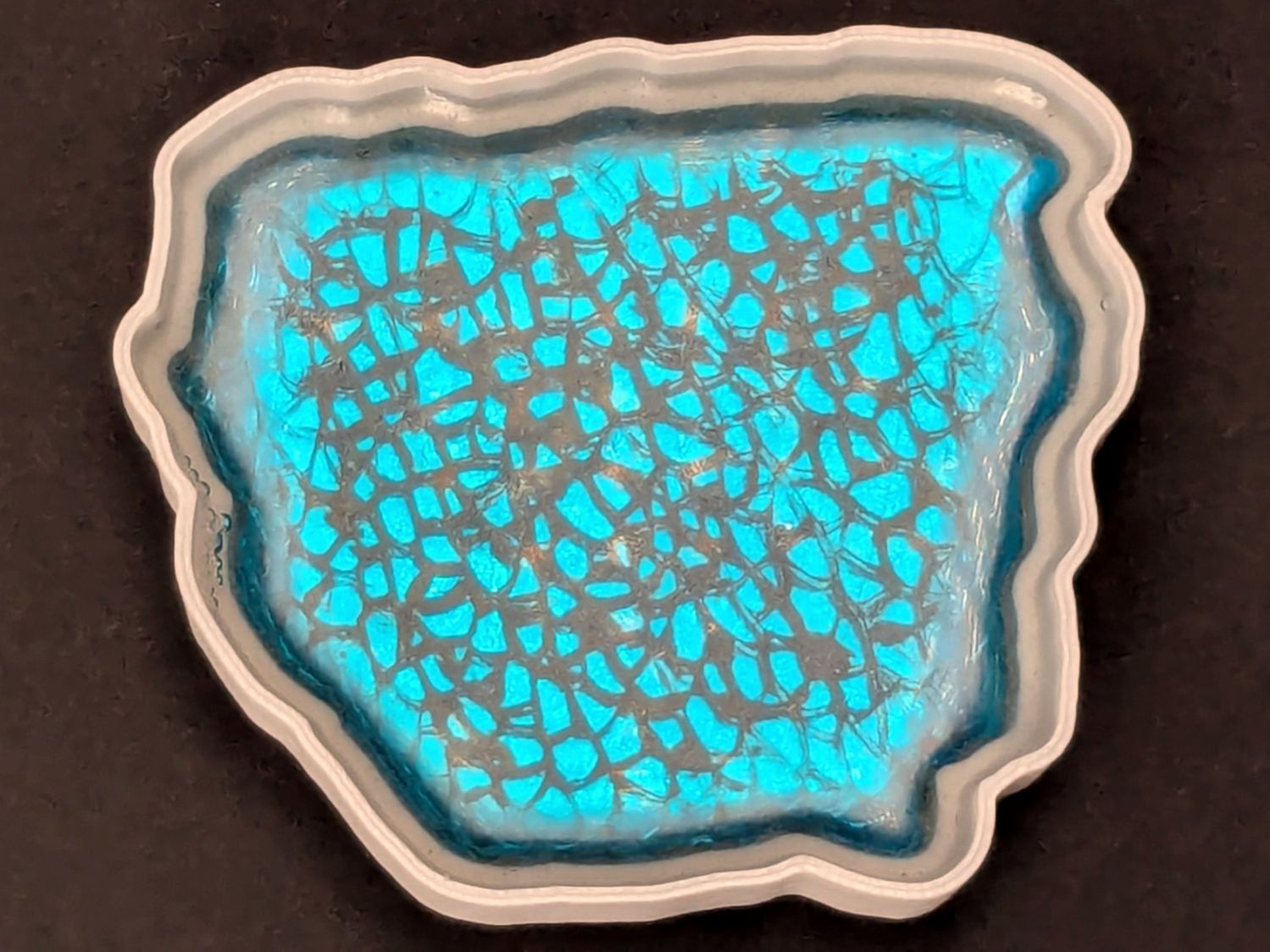
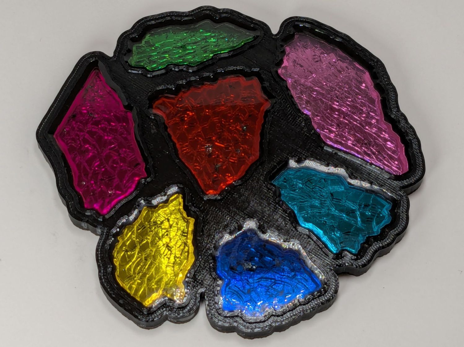
Each recess has a narrow inner lip as a border inside the raised perimeter, which may not be strictly necessary, but IMO nicely sets off the fragments:
Smashed Glass 3D Printed Coaster – Set B
Each fragment must be spaced far enough from its three neighbors to allow for those lips and perimeter walls, which requires more fussing than I’m willing to apply on a regular basis.
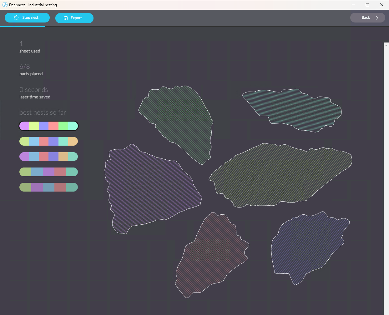
So fetch & install Deepnest to fuss automagically. The program hasn’t been updated in years and the Linux version segfaults on my Manjaro boxen, but the Windows version runs fine on the Mini-PC I use for LightBurn:
Deepnest Fragment Set E – in progress
The Mini-PC runs maxi-hot, though, so at some point I must install Deepnest on the Token Windows Laptop for more grunt.
Deepnest requires a large shape representing the “sheet” in which to arrange the other pieces, so:
Import the fragments outlines into LightBurn
Create a suitable circle
Export circle + fragments as an SVG file
Import into Deepnest
Set 5 mm spacing & other suitable parameters
Let it grind until a nice arrangement pops out
Save as Yet Another SVG file
The output SVG has the fragment outlines arranged to fit within the circle, but does not include the circle. That’s fine, because the next step involves creating a conformal perimeter around the entire group of fragments and preparing it for input to OpenSCAD to create a solid model:
Printed Coaster Layout – 5 inch Set C – solid model
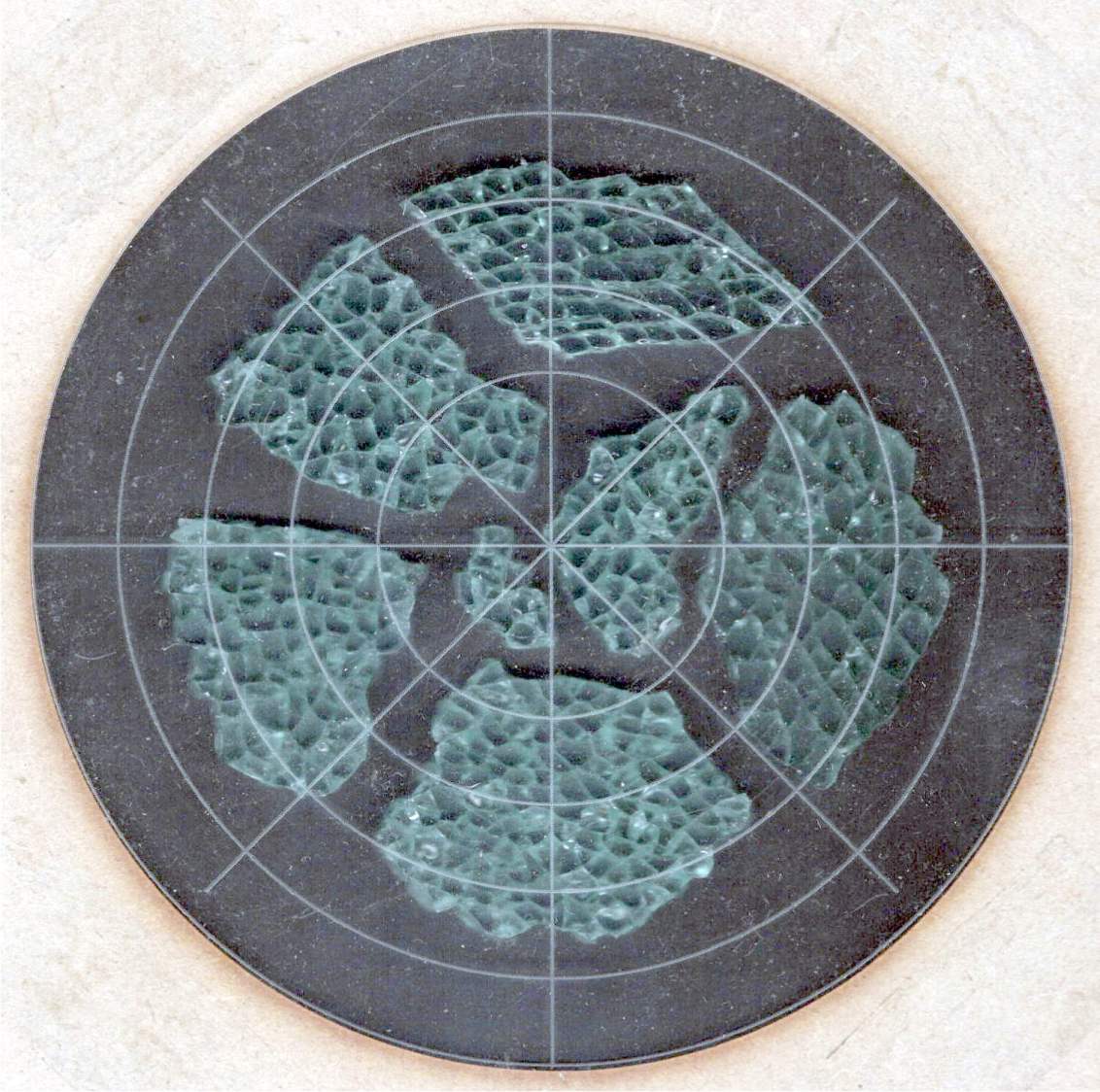
Because all smashed glass fragments are different, the problem boils down to locating their borders in order to create recesses to hold them.
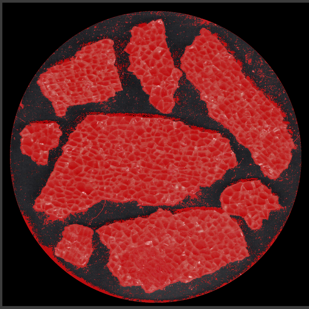
The fragments, being slightly green-tinted glass, have very low contrast against any background color. This picture shows the result of applying GIMP’s Select by color tool with a reasonable color tolerance:
Printed Fragment Coaster – 5 inch – GIMP mask
Fiddling with the tolerance trades off more trash outside the fragments with less accurate selection inside them. While it’s possible to clean up the ensuing mess, it’s incredibly tedious and more trouble than just tracing the edges manually using a stylus and graphic tablet. For the record, a white background produces similar results.
I began tracing the fragments with meticulous attention to following their exact outline, which certainly produced angular shapes:
Smashed Glass paths – quick mask
It also takes approximately forever and is way tedious.
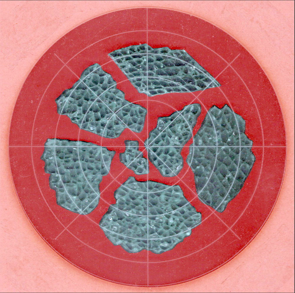
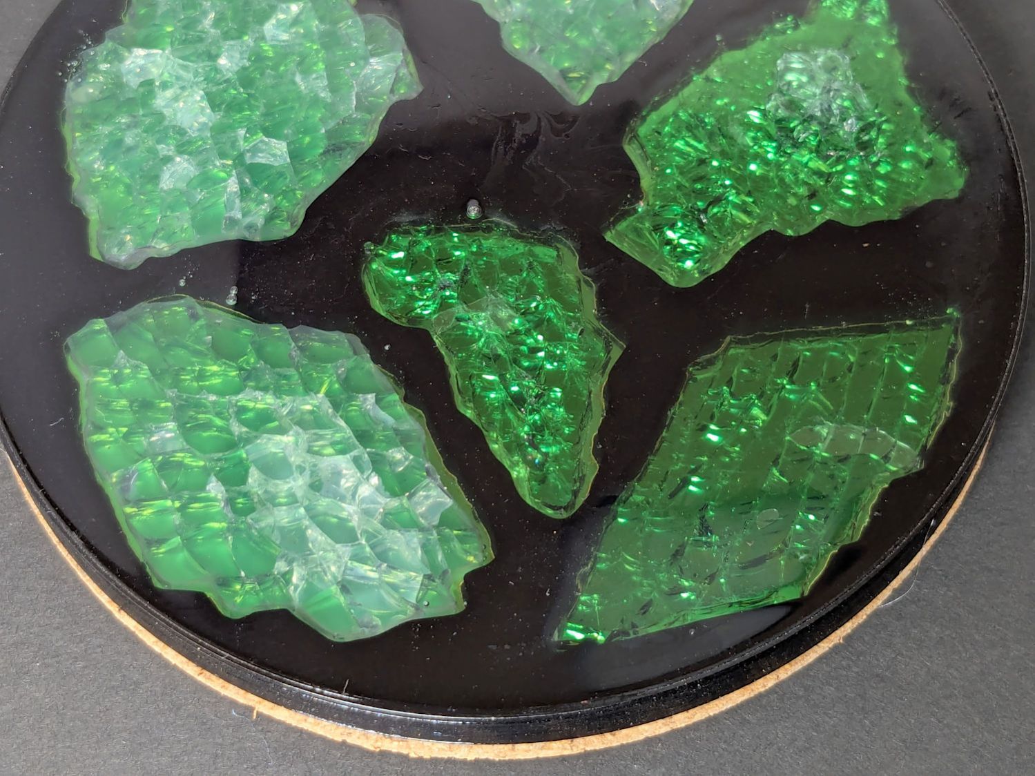
The intent was to apply a uniform offset to those outlines in OpenSCAD, but it turned out the fragment edges aren’t exactly perpendicular to the scanner platform and the protruding glass extends beyond any reasonable offset; determining how unreasonable the offset must be requires cutting a fitting template:
Printed Coasters – fit test
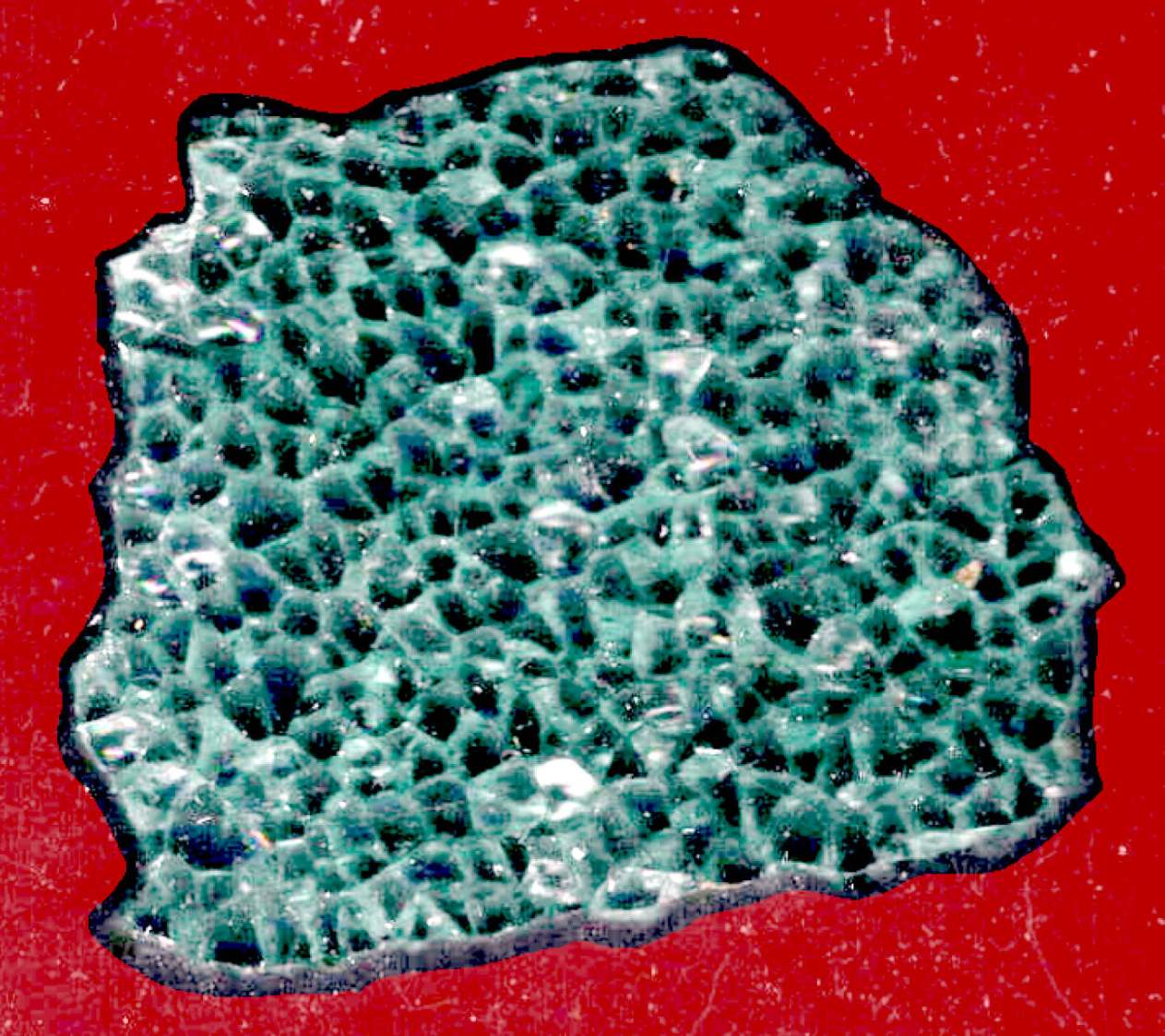
Incidentally, the dark smudge in the bottom fragment isn’t dirt, it’s the Ford logo above the identification numbers for that particular window:
Printed Coasters – glass fragment logo
You’ll note the rather sloppy fit inside the template.
However, the little glass shard sticking out on the upper right side does not match a corresponding template notch. You’re looking at the top of the fragment, but the scanner was looking at the bottom and that shard angles outward toward the top, where it was out of focus and I didn’t notice it.
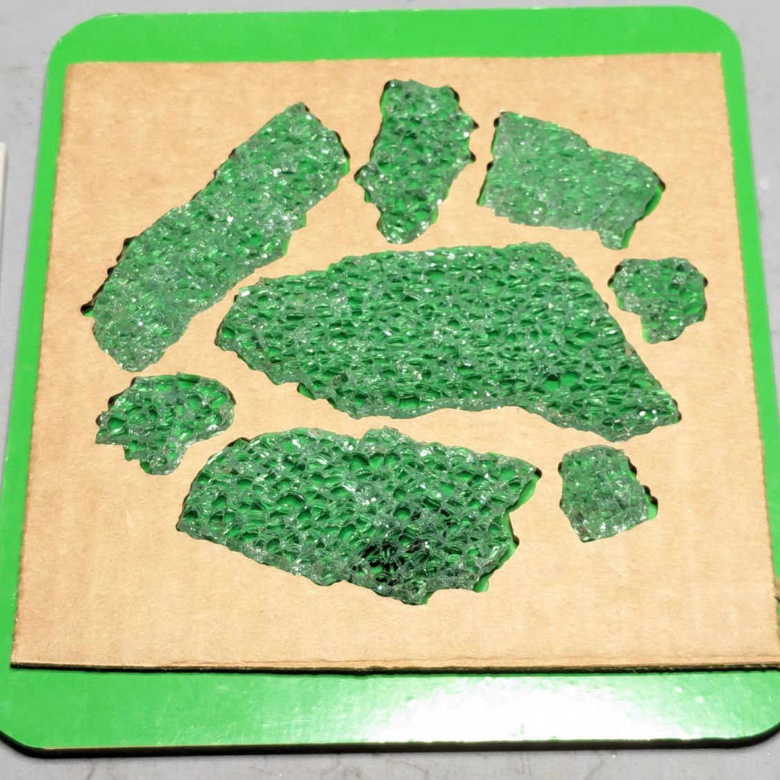
Although that fragment fit its recess, such things eventually cause problems:
Printed Coasters – fragment misalignment
The chipboard template isn’t as tall as the printed recess, which means some of those protruding shards can wiggle through.
Protip: Avoid the temptation to just press a fragment into its ill-fitting recess, as shattered glass doesn’t have much strength. AFAICT, only air pressure holds the shards in place (they’re not windshields and not laminated), so you must handle them like they’re made of ahem glass.
The scans produce 300 DPI images, so each pixel is 0.085 mm across and half a millimeter is about 6 pixels wide. I tried tracing the fragments with the center of a 12 pixel circular GIMP brush, so the outer edge of the brush painted a 0.5 mm margin around the fragment, but keeping the middle of the brush on the edge was entirely too fussy.
I eventually settled on a 6 pixel brush, painted it just outside the margin, and paid more attention to shadows that might be shards protruding toward the top:
Printed Clutter Collector – fragment GIMP selection
That works out well with the fragments on the desk to resolve any issues.
The garish red in those screenshots is GIMP’s Quick Mask mode allowing you (well, me) to paint the selection with either black or white to mask or select the pixels.
After painting the entire perimeter of the fragment, use the Bucket Fill tool to pour white into the interior and select the entire fragment. This is much easier than scribbling over the fragment, which is what I did until I realized I was working too hard.
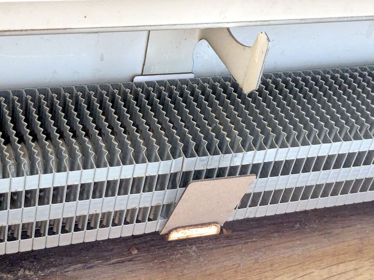
Cleaning the baseboard radiator fins before moving the houseplants back to their winter abode by the living room window made sense, so I took the trim covers off and vacuumed a remarkable accumulation of fuzz off the top and out from between the fins. The covers had an equally remarkable accumulation of sawdust along their bottom edge, apparently deposited when the previous owners had the floor sanded before they moved in a decade ago.
If you happen to live in a house with baseboard radiators, I’m guessing you never looked inside, because nobody (else) does.
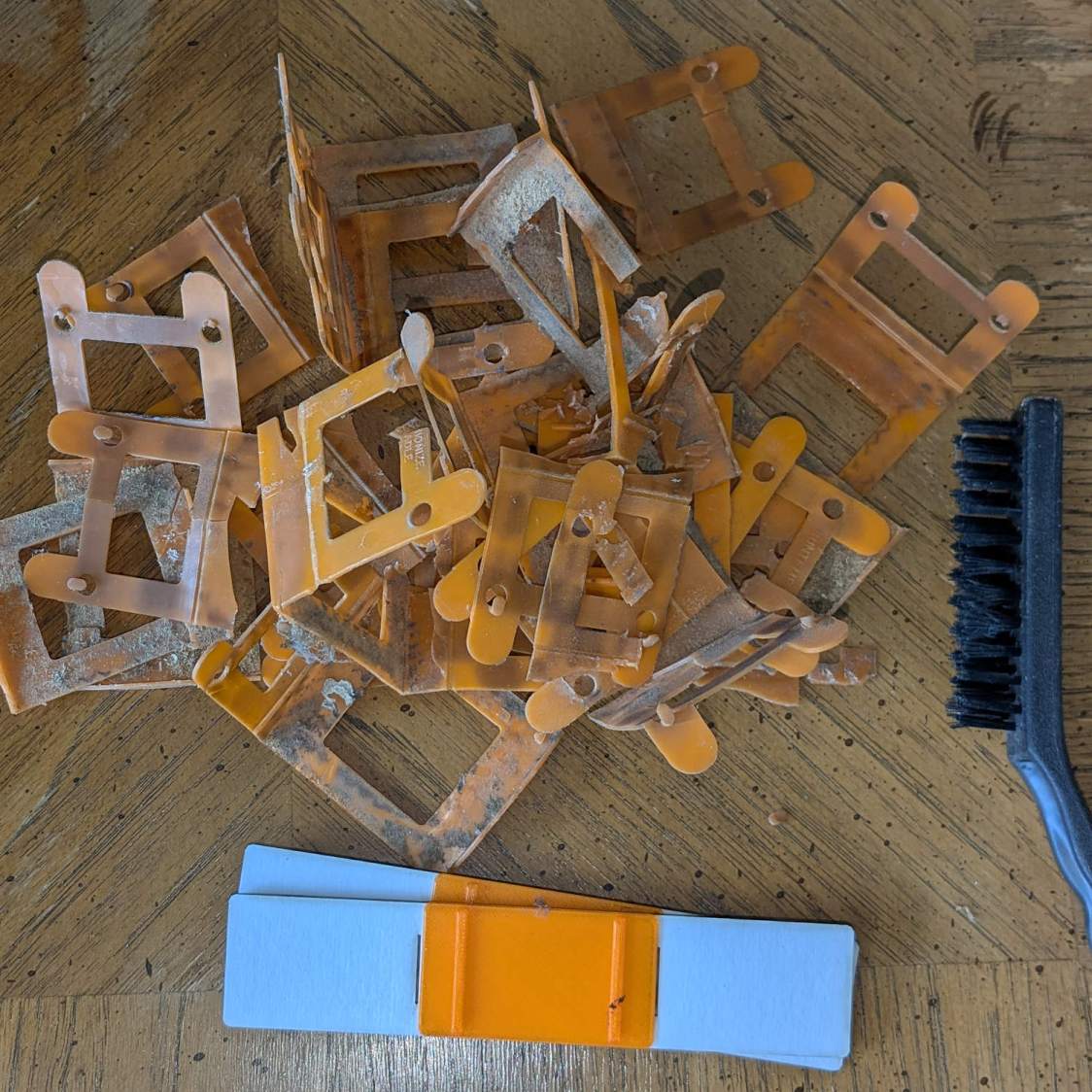
Anyhow, the radiator fins should rest on plastic carriers atop the bent-metal struts also supporting the trim covers, so that they slide noiselessly when the copper pipe expands & contracts during the heating cycle. Over the last six decades, however, the plastic deteriorated and most of the carriers were either missing or broken to the point of uselessness:
Baseboard Radiator Sled – old vs new
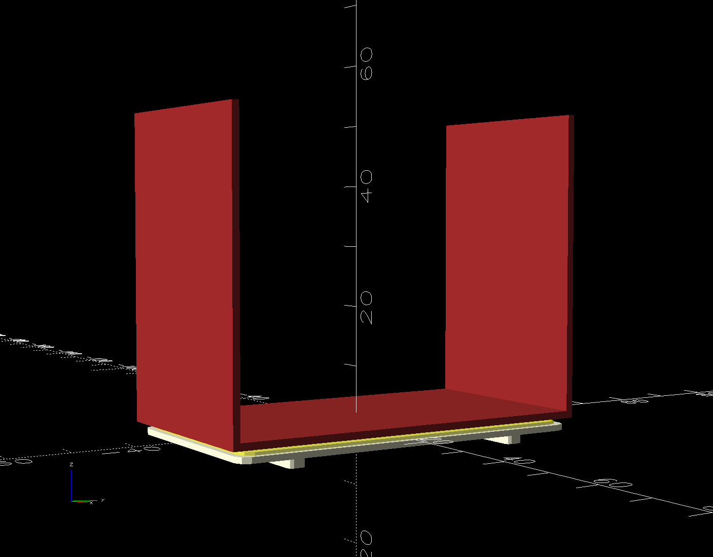
The shapes on the bottom are replacements made with a 3D printed base (“sled”) and a chipboard wrap around the radiator preventing the fins from contacting the strut:
Baseboard Radiator Sled – OpenSCAD show
Although it was tempting to 3D print the whole thing, because plastic, I figured there was little point in finesse: chipboard would work just as well, was much faster to produce, and I need not orient the shapes to keep the printed threads in the right direction.
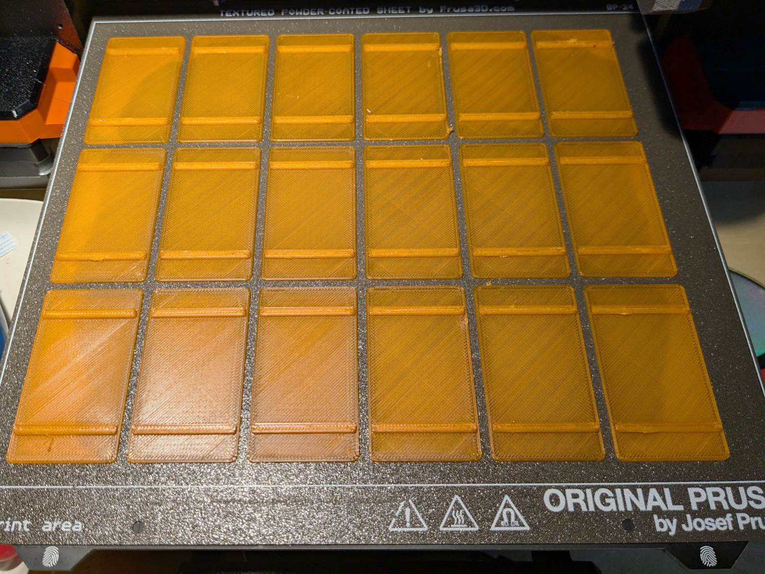
The Prusa MK4 platform was just big enough for the number of sleds I needed:
Baseboard Radiator Sled – printed
The sleds along the left and right edges lost traction as the printing progressed, but everything came out all right.
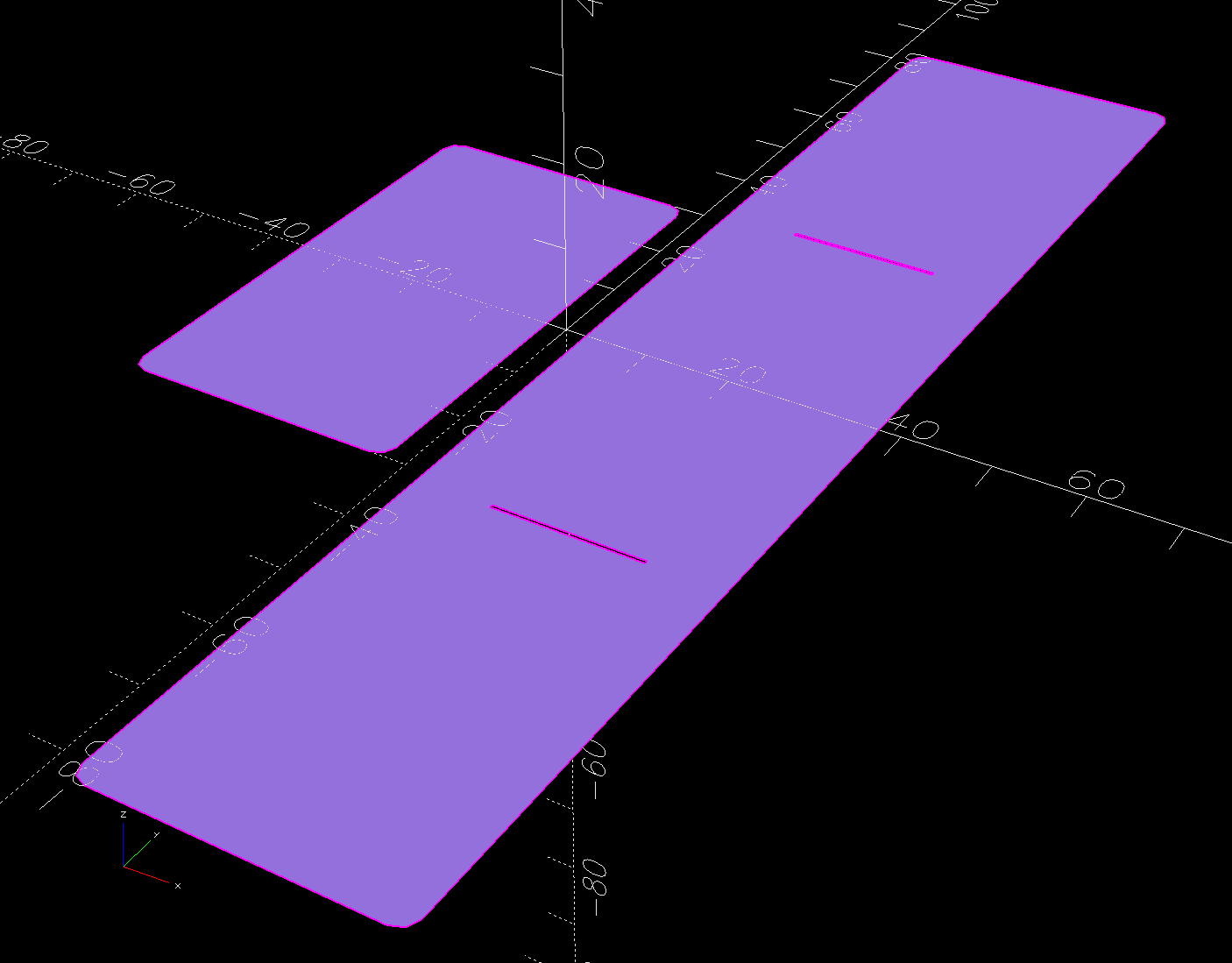
The OpenSCAD program also produces 2D SVG shapes for the chipboard wraps and adhesive rectangles sticking them to the sleds:
Baseboard Radiator Sled – OpenSCAD SVGs
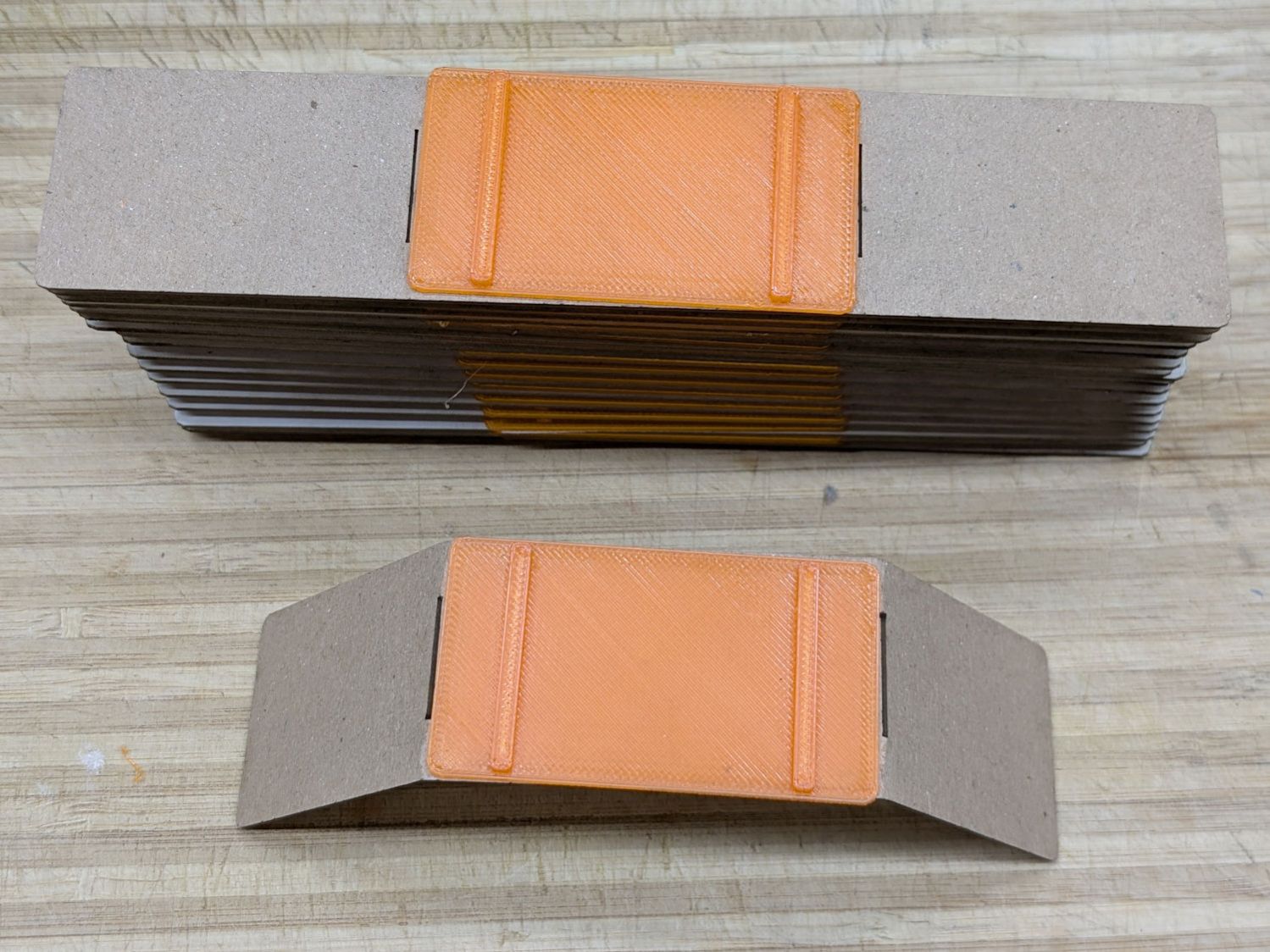
Import those into LightBurn, duplicate using the Grid Array, Fire The Laser, then assemble:
Baseboard Radiator Sled – assembly
The slits encourage the chipboard to bend in the right direction at the right place, so I didn’t need any fancy tooling to get a decent result.
A few rather unpleasant hours crawling around on the floor got the struts bent back into shape and the sleds installed under the fins:
Baseboard Radiator Sled – installed
Protip: Gloves aren’t just a good idea, they’re essential.
The trim cover presses the angled chipboard where it should go against the fins. The covers carry shadows of the plastic carriers, suggesting the clearance was tighter than it should have been and thermal cycling put more stress on the plastic than expected. We’ll never know.
Although I’ll make more for the other baseboards as the occasion arises, I hope to never see these again …
This file contains hidden or bidirectional Unicode text that may be interpreted or compiled differently than what appears below. To review, open the file in an editor that reveals hidden Unicode characters.
Learn more about bidirectional Unicode characters