Ed Nisley's Blog: Shop notes, electronics, firmware, machinery, 3D printing, laser cuttery, and curiosities. Contents: 100% human thinking, 0% AI slop.
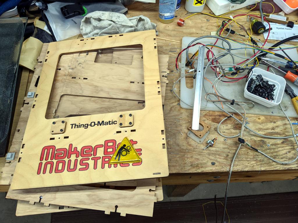
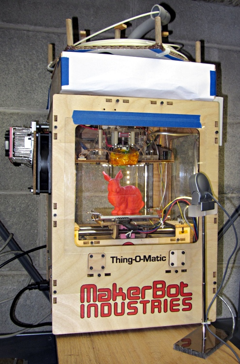
The Thing-O-Matic got me started in 3D printing (and blogging!), provided an education in many useful subjects, and has long since outlived its usefulness.
The recesses in cheap 1/4-inch shank nut drivers aren’t much deeper than the nuts, which means a screw sticking out of the nut by more than a few threads defeats the entire purpose.
Well, I can fix that:
Drilling 5.5 mm socket
That’s a 5.5 mm socket for M3×0.5 machine screw nuts, getting a screw clearance hole drilled into it with a #28 drill (0.1405 inch = 3.5 mm). The sockets are allegedly “forged and hardened”, but an ordinary HSS drill bit cuts like they’re butter, so I’m thinking somebody skipped the hardening step.
Over the next several days, I’ll be screwing around with trying out different blog themes, because WordPress has “deprecated” the theme I’ve been using since about 2011; it no longer works well with their most recent infrastructure. There being no way to tell how any given theme will look, how difficult creating posts may be, or (in truth) anything about a theme without actually running it, I’ll be doing live-fire exercises while posting odds-n-ends projects from the shop.
Some themes strongly suggest require a logo, so you’ll see this monstrosity until something better comes along:
Logo – Isolated 0D3
Speaking of themes, you’re looking at a “free” blog on wordpress.com, not something I’ve conjured by installing the open-source blog infrastructure from wordpress.org on a server, which means few things you (think you) know about a “WordPress blog” apply. In particular, free blogs on wordpress.com lack access to the universe of themes & plugins applicable to a DIY FOSS installation.
(I think) I’d be perfectly happy to compose posts in Markdown (or some such) and slam them into a static site generator (Hugo / Gatsby / whatever), rather than slog through WP’s GUI editor, but I think my usual post-a-day pace conflicts with the fundamental assumptions of a “static site” generator.
I value blog comments from real people (you all know who you are and I thank you!), but blogspam presents a clear & present danger. Right now, Akismet kills nearly all the hundreds of spam comments per day; it’s obvious any blog comment system must include robust spam filtering. The alternative of, say, running a separate email list for comments seems far more trouble than it’s worth.
I absolutely do not want to sysop my very own blog configuration on a rented server / VPS / Digital Ocean Droplet / whatever. Things like WPengine.com would be attractive, except that this blog’s very long tail generates enough traffic to come very close to the 25 k visit/month upper limit of their “startup” plan; I’m reluctant to pay $100/month for the 100 k visit/month “growth” plan just to host my shop notes.
The open cells on the back side show the wasps don’t waste any effort on putting mud where it’s not needed:
Organ Pipe Wasp Nest – wall side
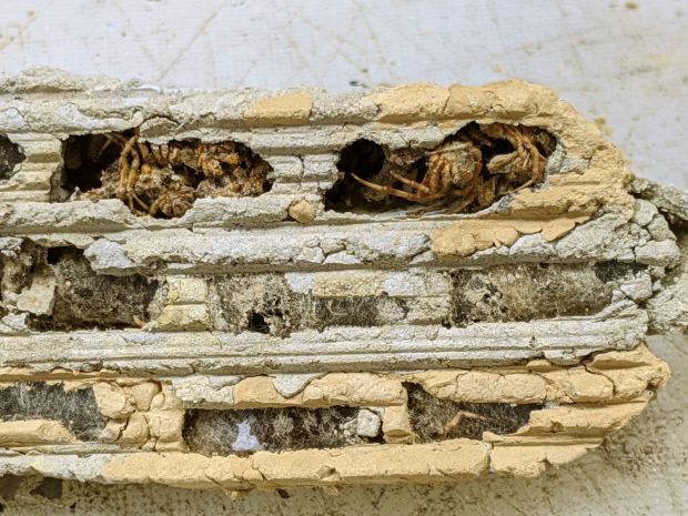
Cracking it in half shows the rugged walls between the cell columns:
Organ Pipe Wasp Nest – cross section
Several cells contained three or four (thoroughly dead!) spiders apiece, evidently the result of un-hatched eggs:
Organ Pipe Wasp Nest – failed egg – spiders
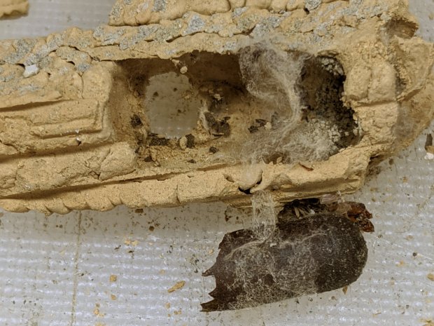
Each successful cell contained a brittle capsule wrapped in a thin cocoon, surrounded by fragments of what used to be spiders, with an exit hole chewed in the side:
Organ Pipe Wasp Nest – capsule detail
I regret not weighing the whole affair, as all that mud represents an astonishing amount of heavy hauling and careful work by one or two little wasps!
No surprise, as the car completely shattered the utility pole.
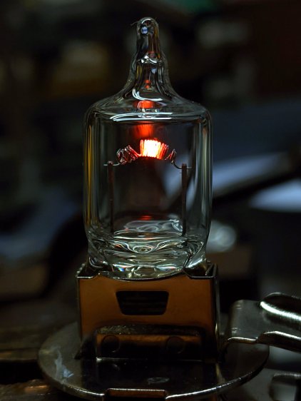
The glow draws 1.5 A from a bench supply at 1 V, just to show the filament isn’t lighting up evenly across those gaps. The bulb runs at 55 W from 12 V and would be, I’m sure, blindingly bright, although the heat concentrated in those few coils suggests it’d burn out fairly quickly.
By LED standards, though, you don’t get much light for your 1.5 W …
An underexposed version highlights the filament, just for pretty:
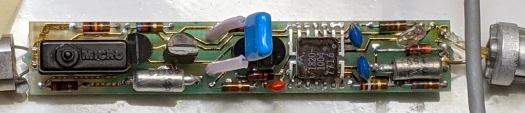
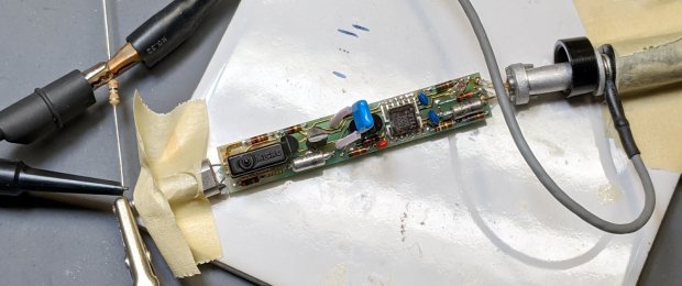
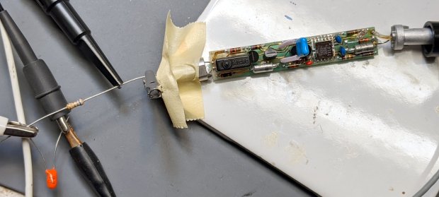
When I re-capped the HP 10525T Logic Probe, I expected the matching HP 10526T Logic Pulser would require the same treatment. Having finally gotten a Round Tuit, I preemptively pulled it apart to see what was going on inside:
The IC is a Motorola SN7404 Hex Inverter sporting an HP house number in a ceramic flatpack: pin 1 in the upper right, VCC on pin 4, and common on pin 11. The 7716 datecode suggests the chip first saw daylight shortly after single-chip microcontrollers became a nontrivial thing.
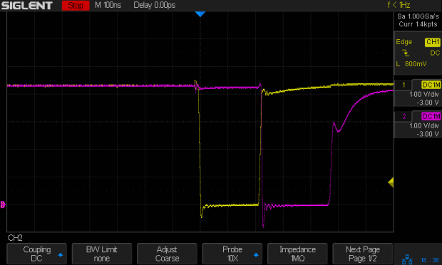
The pushbutton switch triggers the expected pulses at pins 10 (purple) and 12 (yellow), with timings controlled by the RC networks:
U1.12 U1.10
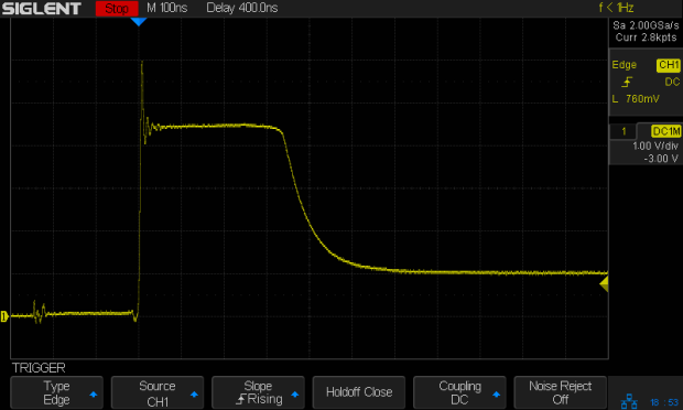
The collector output of Q2 is a robust 73 mA pulse through its 62 Ω resistor:
Q2.c
Q1 dumps 15 mA into its 300 Ω resistor:
Q1.C
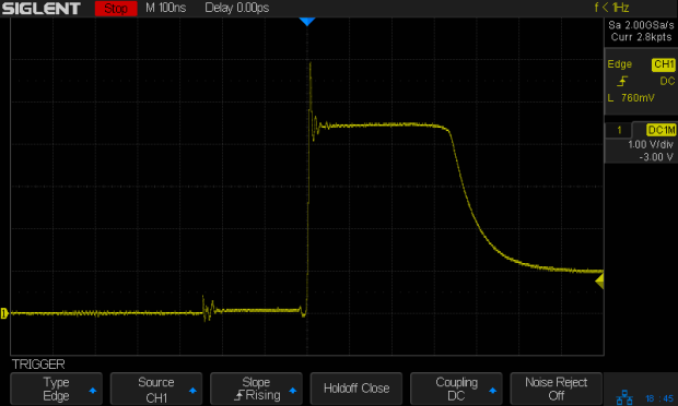
The push-pull output at the emitter of Q3 and the collector of Q4 looks similar (albeit with some delay cranked in to show the tidy exponential tail):
Q3.e – Q4.c
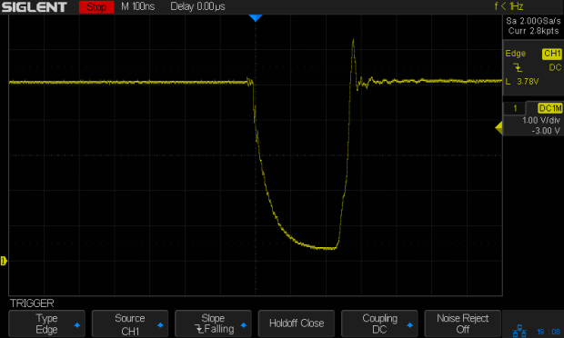
The manual specifies a 3.0 Ω resistor to ground for Test A, thusly:
HP 10526T Logic Pulser – Test A setup
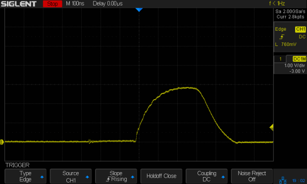
The output peaks at nearly 3 V to drive a robust 1 A (!) pulse:
Test A pulse
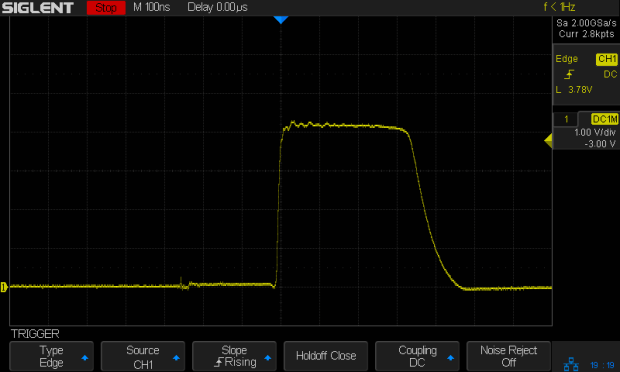
Test B requires a 6.2 Ω resistor driven from 5 V, but a 6.8 Ω resistor came to hand:
HP 10526T Logic Pulser – Test B setup
The downward pulse doesn’t quite reach 0 V (because saturation voltage, etc), so it’s a mere 725 mA:
Test B pulse
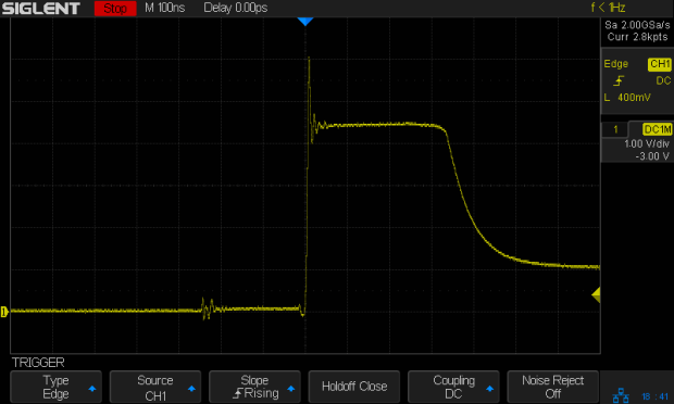
HP’s formal setup for Test C requires a totalizing counter to show the pulser produces exactly one pulse for each button push. I just wired up a 47 Ω resistor and eyeballed a few pulses:
Test C pulse – 47 ohm
The lighter 85 mA load through the resistor allows a more rectangular pulse than the 3 Ω resistor. Yup, looks clean to me.
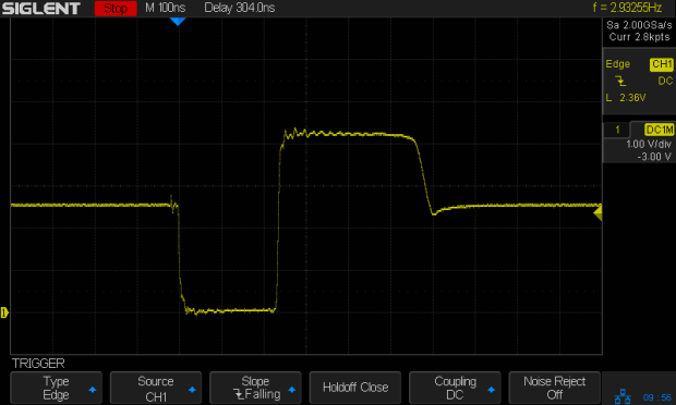
Because the pulser drives its output both low and high with great authority, it doesn’t care what state the external net wants. Here’s what happens with the 47 Ω resistor connected to a 2.5 V supply:
Bipolar pulse – 47 ohm 2.5 V
No matter where the logic family’s threshold might be, the net will experience one downward and one upward transition through it: with the pulser delivering nigh onto an amp, the net’s driver doesn’t stand a chance.
However, the pulser was designed for TTL and DTL (remember DTL?) circuitry, so hammering a 3.3 V microcontroller pin probably isn’t a Good Idea. The notion of keeping a pulser around Just In Case may have reached its end times.
Oh, and about the re-capping. Turns out HP used solid tantalum capacitors and they’re still doing fine after four decades, thankyouverymuch. I put it back together and expect it will continue working forevermore.
For reasons not relevant here, I made another clamp for a magnifying desk lamp and mailed it off in a small box. A few measurements suggested all such lamps share a common design and similar parts, so I duplicated my previous attempt, with some improvements.
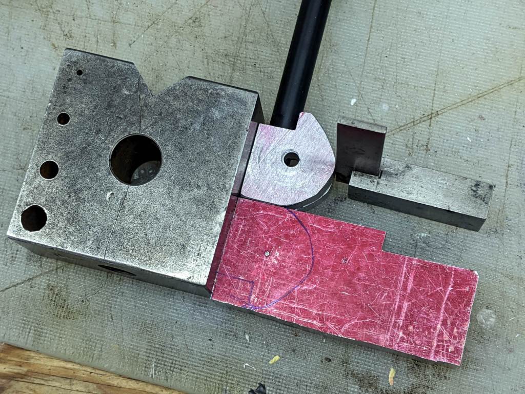
On the upside, the same scrap of aluminum plate I used for the previous clamp emerged from the stockpile and, after a session with Mr Disk Sander, sported two square & reasonably perpendicular sides:
Magnifying Lamp Clamp – squaring stock
Rather than rely on my original dimension scribble, I transfer-punched the hole location from my as-built clamp to the stock:
Magnifying Lamp Clamp – locating stem hole
That’s a reenactment based on a true story: the actual punching happened on the bench vise’s anvil surface, with too many moving pieces supported & aligned by an insufficient number of hands.
Drilling the 5/16 inch hole required mounting the Greater Chuck on an MT1 taper adapter for the Sherline:
Magnifying Lamp Clamp – drilling stem clamp
It’s normally on an MT2 adapter for the mini-lathe tailstock, where it handles drills up to 3/8 inch. For the record, the Sherline’s Lesser Check tops out at 1/4 inch and the Least Chuck at 5/32 inch.
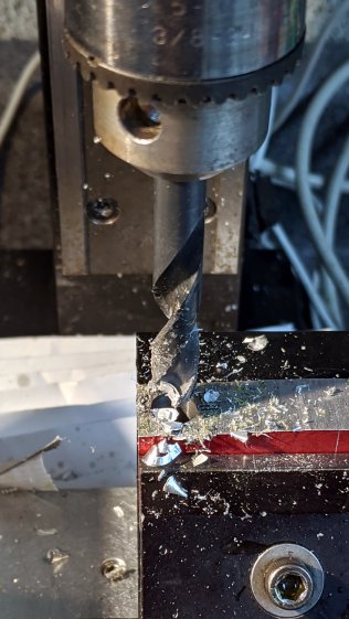
Punch & drill the 4 mm cross hole for the clamping screw:
Magnifying Lamp Clamp – drill cross hole
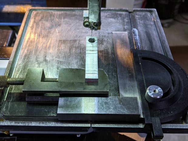
Grab the plate in a toolmaker’s vise, set up some casual guidance, and bandsaw right down the middle:
Magnifying Lamp Clamp – sawing clamp halves
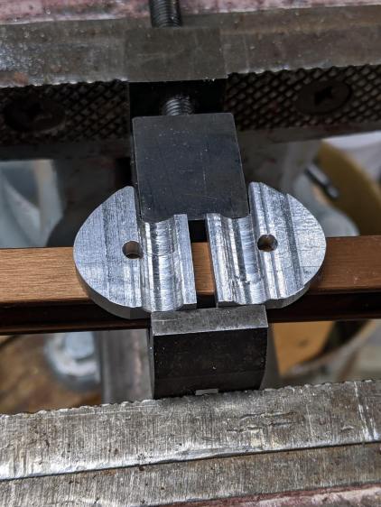
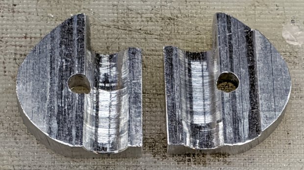
Bandsaw the outline to free the two halves from the stock, then clean up their perimeter:
Magnifying Lamp Clamp – rounded
Saw the clamp clearance almost all the way through to leave a protrusion, then file the scarred kerf more-or-less flat:
Magnifying Lamp Clamp – filing interior
Do a trial fit in my lamp, which lacks the fancy brushed-metal finish of the remote one:
Magnifying Lamp Clamp – trial fit
It holds tight and rotates well, so break the edges and shine up the outside to a used-car finish (“high polish over deep scratches”):
Magnifying Lamp Clamp – surface finish
The inside remains gritty to improve traction on the lamp stem: