Ed Nisley's Blog: Shop notes, electronics, firmware, machinery, 3D printing, laser cuttery, and curiosities. Contents: 100% human thinking, 0% AI slop.
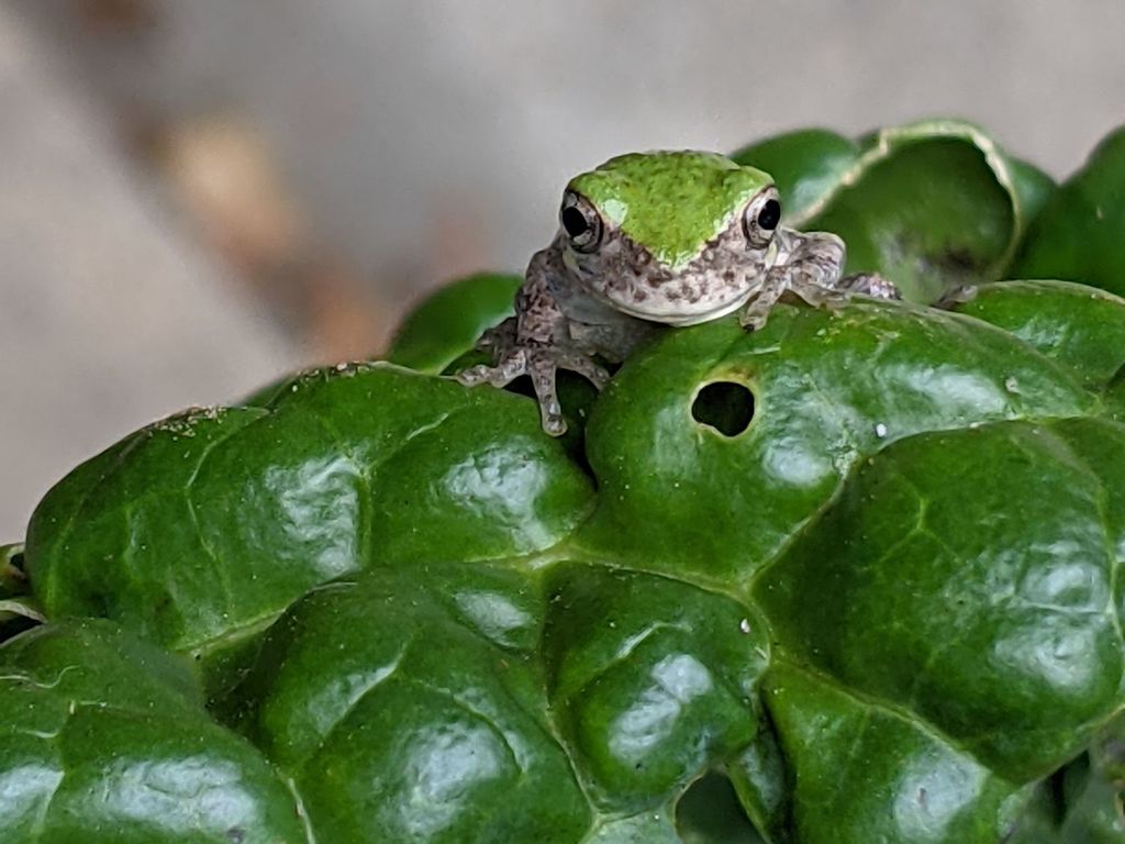
Mary found another tree frog while picking Savoy lettuce for breakfast:
Tree frog on Savoy cabbage
They’re much better camouflaged in their (more or less) natural surroundings, so I didn’t spot it at first, either.
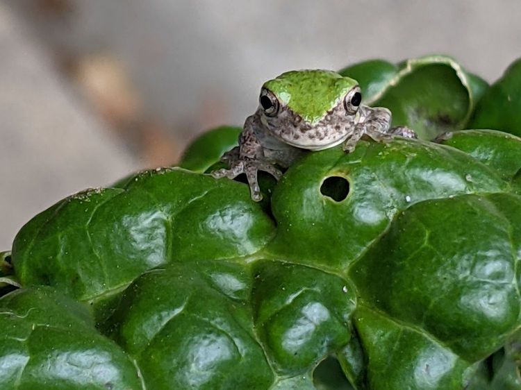
They really are cute little gadgets:
Tree frog on Savoy cabbage – detail
This is only the fourth tree frog she’s seen in the last two decades, but the second one in a month. It may be the same frog as before, although the garden now has a rather husky resident snake who seems to be eating well.
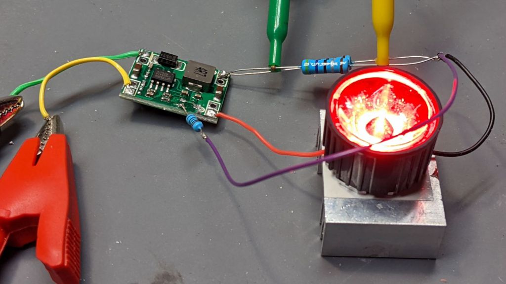
MP1584 buck regulator – current feedback – red LED
I started with the same 1.65 Ω sense resistor and got the same 484 mA current, with the LED forward drop at a surprisingly high 3.3 V = 1.6 W. Ouch.
Adding a 1 Ω series resistor to get 2.65 Ω lowered the current to 300 mA with a forward drop of 2.45 V = 740 mW.
Running the numbers suggested a 2.3 Ω sense resistor made from a pair of parallel 4.7 Ω resistors, which produced 346 mA and an LED drop of 2.66 V = 920 mW. The resistor dissipates 280 mW.
The bench supply provides 6.3 V @ 200 mA = 1.26 W, so the overall efficiency is 94% and the LED burns 73% of the input.
The PCB is the generic MP1584 buck regulator, as seen before in its normal voltage feedback mode, rewired to get feedback based on the LED current, so that it adjusts the output voltage to maintain a constant LED current, regardless of LED forward drop variations.
Pin 4 normally sees the output voltage divided down to the 0.8 V error comparator reference voltage:
MP1584 – buck regulator – voltage feedback
Yes, the MP1584 is “not recommended for new designs”, which surely accounts for the myriad cheap regulators built around it. Somebody picked up a great deal on a vast pile of obsolete ICs and is passing the savings along to us; there are exactly zero hits for MP2338 buck regulators.
Putting the ballast resistor on the low side of the LED turns it into a current sensor:
MP1584 – buck regulator – LED current feedback
Pick R to drop 0.8 V at the desired LED current and It Just Works™.
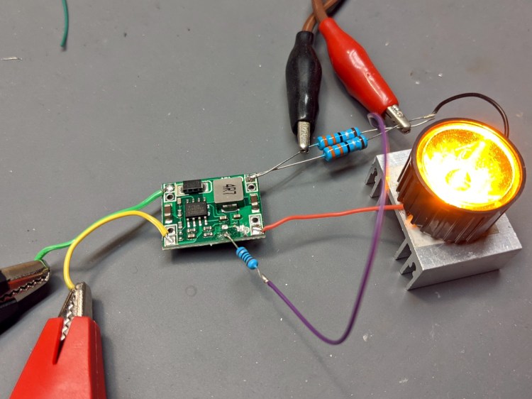
The two 3.3 Ω resistors in the top photo produce a 1.65 Ω sense resistor to set the LED current at:
485 mA = 800 mV / 1.65 Ω
It actually works out to a bit higher than that, because I stuck a 100 Ω resistor in series with the feedback input. The PCB still has the 8.2 kΩ resistor from the original voltage divider, so the error amp sees only 99% of the sense voltage, but it’s close enough.
With 6.3 V and 0.28 A = 1.76 W from the bench supply over on the left, the regulator puts 490 mA through the LED. The LED drops 2.54 V = 1.24 W and the resistor drops 0.809 V (that 1% thing) = 0.4 W for a total of 3.35 V and 1.64 W. The regulator is 93% efficient, although the resistor burns a quarter of the energy.
One could use a Hall effect current sensor and an op amp circuit to deliver the proper feedback voltage without resistive loss, but I think burning half a watt is Good Enough for the purpose.
One could add parallel resistors with MOSFET switches to set the LED current. An unswitched resistor would set the lowest current, with switched parallel resistors lowering the resistance, raising the current, and brightening the LED.
The PCB leaves the Enable input floating with an internal pullup. Grounding the pin shuts off the LED as you’d expect, so I can blink the LED without any further hassle.
One could imagine simultaneously blinking and brightening the LED as needed.
Photo from the Pixel 3a, zoomed all the way, and showing why digital zooming isn’t the way to get nice pictures. On the other paw, it’s the camera I always have with me.
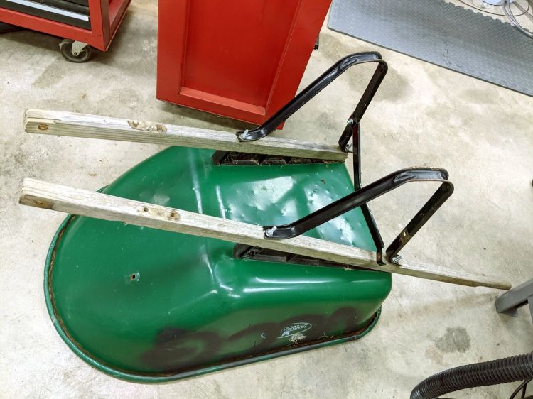
For reasons that should be obvious by now, I volunteered to rebuild a wheelbarrow used at the Vassar Community Garden plots. It spent all its time outdoors and one of the handles eventually broke off:
Wheelbarrow rebuild – old handles
I’d already removed the wheel and front strap, which were in good condition.
The new handles were undrilled, so I marked and drilled them with a nice brad-point bit to get clean holes:
Wheelbarrow rebuild – handle drilling
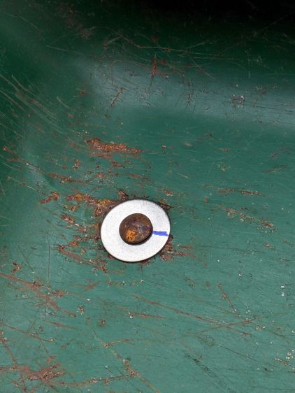
The metal “barrow” had cracked around the carriage bolts holding it to the frame, so I filed a quartet of fender washers to fit the square section under the heads:
Wheelbarrow rebuild – fender washer holes
After a false start, I marked the bolt heads and washers to line them up properly while tightening the nuts on the other end:
Wheelbarrow rebuild – fender washer installed
One front strut had gone missing, so I replaced it with a mashed-and-drilled section of ski pole:
Wheelbarrow rebuild – front strut
All in all, a few hours of Quality Shop Time interspersed with a few pleasant bike rides to various local stores, wherein I learned who doesn’t stock the necessary hardware.
Protip: Home Depot has the highest-entropy hardware assortment.
For the record, all the bolts have a 5/16-18 thread.
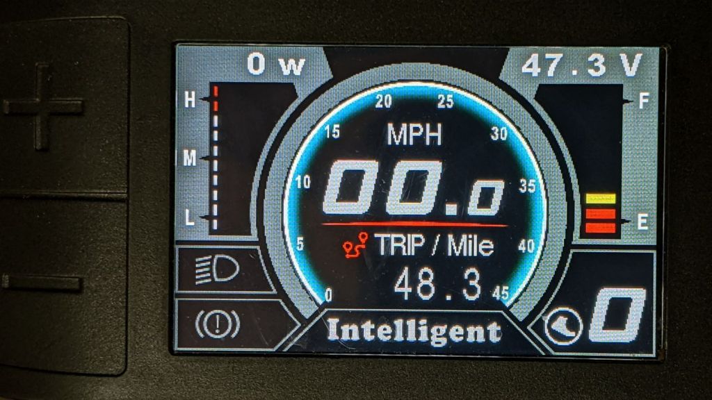
After a few days of riding, the Bafang 500C display on Mary’s bike gives the battery status:
Bafang 500C display – 48 mi 30 pct
The thermometer scale on the right shows 30% remaining battery capacity after 48.3 miles of riding, with the 11.6 A·h battery at 47.3 V.
For our type of riding, each 10% increment of battery charge delivers about 7 miles of range. Although we could probably get 70 miles between charges, recharging the battery at 20 to 30% makes more sense; the bike is in the garage, so why not?
Our typical 10 to 15 mile rides now average 12+ mph, with some level sections ticking along at 18 mph (giving me some serious exercise), which isn’t much by pro rider standards.
Computing the lithium battery charge state by measuring its voltage isn’t particularly accurate, but it’s about as good as you’re going to get.