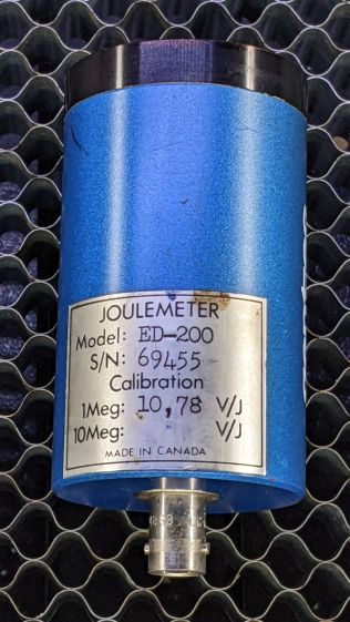
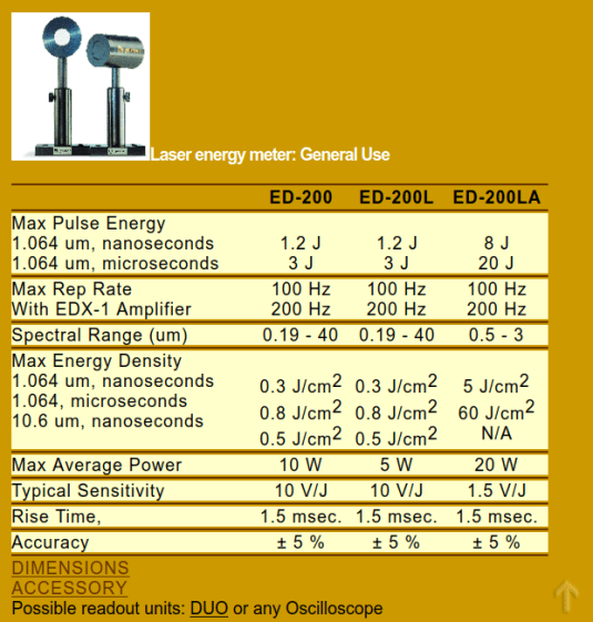
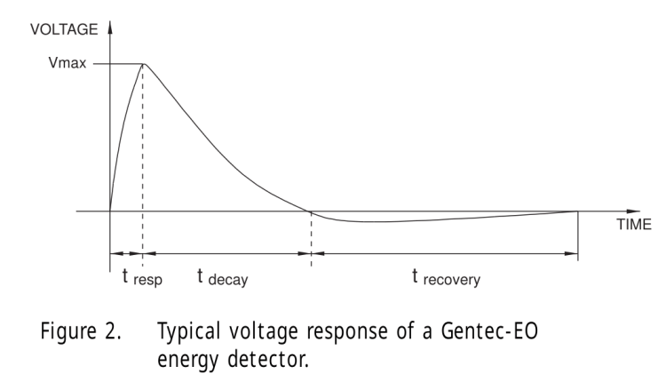
The Gentec ED-200 Joulemeter is severely underqualified to measure the OMTech 60 W laser’s beam power, because the laser’s 1 ms minimum manual pulse width isn’t much shorter than the sensor’s 1.5 ms risetime and the maximum beam power is far too high for the sensor’s health. With that in mind, I set the PWM power to 50% = 30 W (grossly too high) and looked at the peak output voltage for a series of (far too long) pulse widths:
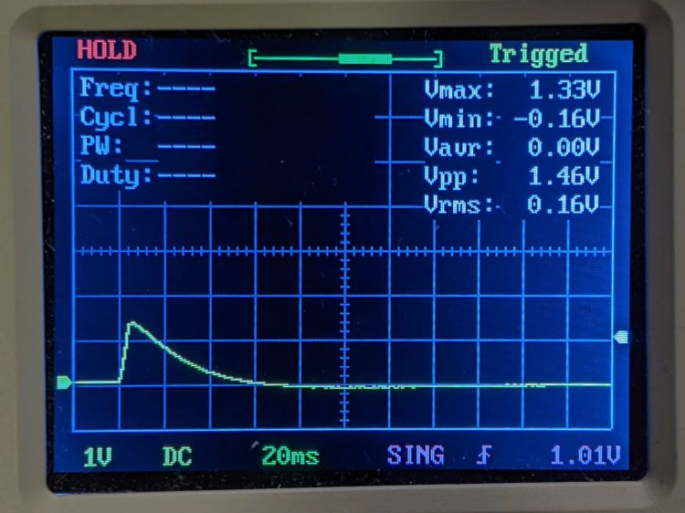
Rounding the detector sensitivity to 11 V/J says the 1.3 V peak at 5 ms corresponds to 120 mJ and 24 W:
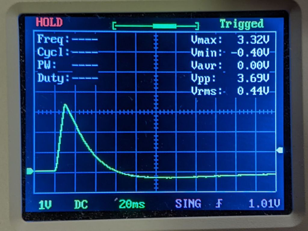
The 3.3 V peak at 10 ms is 300 mJ and 30 W:

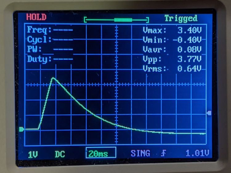
The 3.4 V peak at 15 ms is 310 mJ and 21 W suggests the PWM power output is not nearly as constant as one might expect, although the pulse width looks fine:
The 6 V peak at 20 ms is 550 mJ and 27 W, although the on-screen display obscures the top:
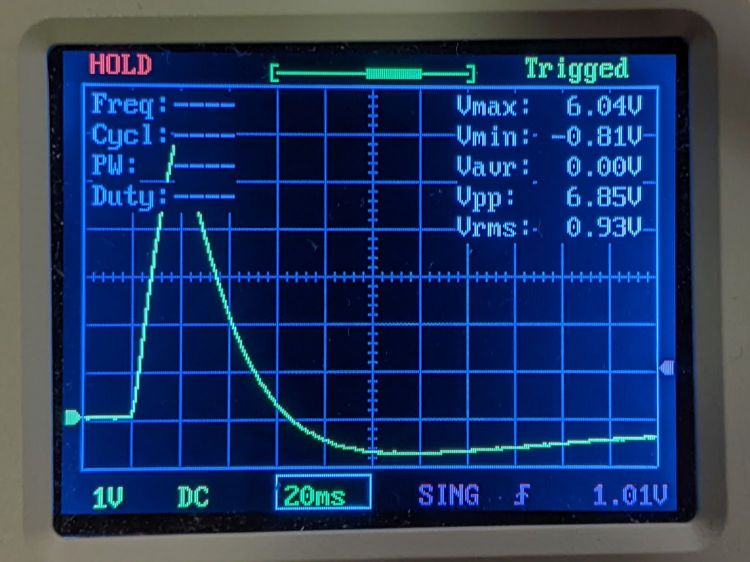
Another 20 ms pulse without the OSD produces a peak eyballometrically close to 6.4 V for 580 mJ and 29 W:

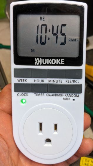
The KT332N controller in the OMTech 60 W laser has a pulse duration setting showing tenths of a millisecond, but (based on some additional measurements) the beam power can vary by 25% for successive pulses in the low millisecond range, so the pulse width resolution doesn’t seem to provide useful control.
Despite the over-long pulses, the calculated power corresponds surprisingly well with the nominal laser output power.
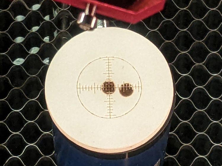
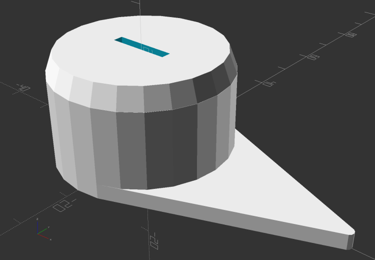
The 1 ms pulses used in LightBurn’s Dot Mode are consistent enough to punch essentially identical 0.2(-ish) mm holes in manila paper to mark the graticule:
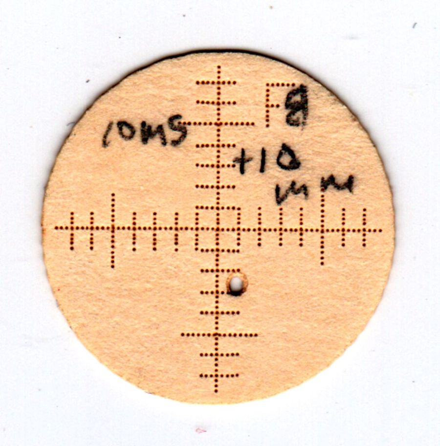
They’re on 0.25 mm centers, with slight variations showing the difference between stepper resolution and positioning accuracy. The shorter graticule lines have three holes on one side of the center lines and four on the other, despite the design’s 1 mm length on both sides; I think there’s a missing dot on the side where the head starts the line, perhaps due to a picket-fence error.
The large beam hole came from two 10 ms pulses, one at the focal point and another 10 mm lower.


