The Smell of Molten Projects in the Morning

Ed Nisley's Blog: Shop notes, electronics, firmware, machinery, 3D printing, laser cuttery, and curiosities. Contents: 100% human thinking, 0% AI slop.

Author: Ed

  • Dremel Flex Shaft Oiling

    Dremel Flex Shaft Oiling

    While using a Dremel cutoff wheel to shape a lathe bit, the flexible shaft sounded not quite noisy, if slightly less smooth than before, so easing some oil into the drive shaft might be a Good Idea. The springy shaft slides out of the motor end without disassembly, but, just for completeness, I took a look inside the handpiece:

    Dremel flex shaft - handpiece internals
    Dremel flex shaft – handpiece internals

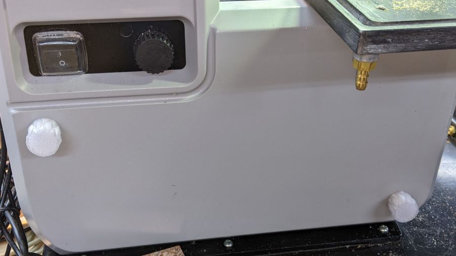
    Before removing the two obvious screws holding the handpiece together, remember to remove the steel ring at each end. The tail ring is obvious:

    Dremel flex shaft - tail ring
    Dremel flex shaft – tail ring

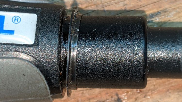
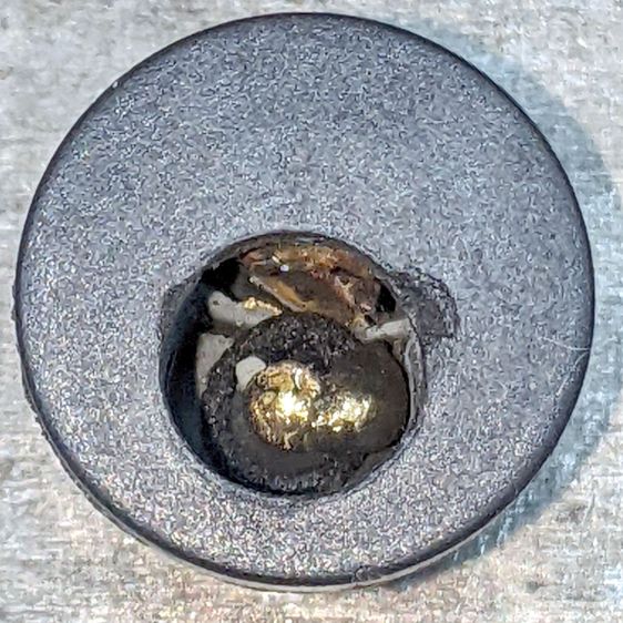
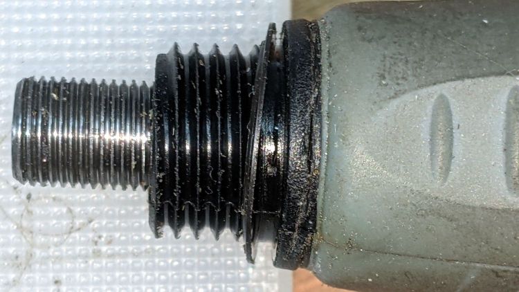
    The nose ring wasn’t where I expected it, but released easily after the obvious mistake revealed itself:

    Dremel flex shaft - nose ring
    Dremel flex shaft – nose ring

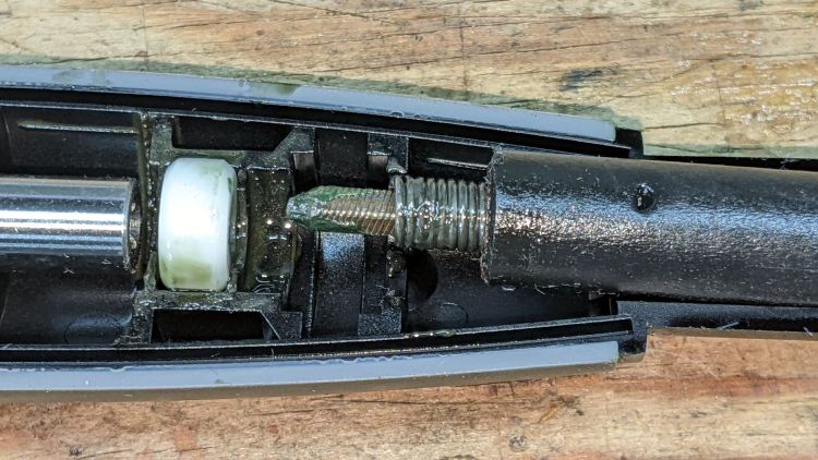
    The steel shaft spun freely in its bearings and the matching end of the flex drive shaft had plenty of grease:

    Dremel flex shaft - drive detail
    Dremel flex shaft – drive detail

    So I just reassembled everything in reverse order. The trick is to line up the existing indentations in the outer sheath with the bumps inside the handpiece shell:

    Dremel flex shaft - housing detail
    Dremel flex shaft – housing detail

    After all that, spreading a few drops of high-speed spindle oil along the spring drive shaft seemed appropriate.

    Didn’t make the least bit of difference to the sound, but I feel better.

  • MicroMark Bandsaw Cover Screw Knobs

    MicroMark Bandsaw Cover Screw Knobs

    These descend directly from the LMS Mini-Lathe cover knobs:

    Micro-Mark bandsaw cover screw knob
    Micro-Mark bandsaw cover screw knob

    The top pair of screw heads aren’t quite flush with the cover, so the knobs have 1 mm extensions:

    Micromark Bandsaw - cover screw knobs - upper
    Micromark Bandsaw – cover screw knobs – upper

    The bottom pair sit inside 4 mm recesses, so those knobs get matching extensions:

    Micromark Bandsaw - cover screw knobs - lower
    Micromark Bandsaw – cover screw knobs – lower

    Attacking an anonymous 5 mm hex wrench with a Dremel cutoff wheel produced a quartet of 12 mm shafts and reduced drawer clutter by one unit.

    In retrospect, I should have dismantled the cover, grabbed the screws in a vise with their shafts vertical, and epoxied all the knobs with perfect alignment. Next time, maybe.

  • Tektronix AM503: Adjustment

    Tektronix AM503: Adjustment

    Having put the Tek AM503 with the 4 MHz oscillation (B075593) on the shelf pending arrival of what might be the world’s last remaining NOS 2625 op amp in the “screened and tested” 156-0317-03 grade, I figured I might as well go through the adjustment procedure on one of the bench units (B064098) to reset the gain and reduce the peaky leading edges (green trace):

    Tek AM503 - B031510 B064098 - 10mA-div
    Tek AM503 – B031510 B064098 – 10mA-div

    I conjured a low-budget Special Adapter to feed signals into the front-panel connector:

    Tektronix AM503 Special Adapter
    Tektronix AM503 Special Adapter

    I also used a somewhat smaller resistor in place of the required 3 Ω 3 W wire-wound unit:

    Tek AM503 - 3 ohm test resistor
    Tek AM503 – 3 ohm test resistor

    It need only soak up a few seconds of the degaussing signal and never even got warm, so it’s all good.

    To my surprise, the square-wave output of the JDS6600 Function Generator meets the 10 ns risetime requirement:

    JDS6600 Fn Gen - risetime 50 ohm
    JDS6600 Fn Gen – risetime 50 ohm

    Perhaps half an hour of adapter shuffling and trimmer twiddling later, the AM503 output looked better:

    Tek AM503 - compensation adj
    Tek AM503 – compensation adj

    The (purple) input comes from the function generator output through a BNC tee and an unterminated foot of coax, so the leading edge ringing is perfectly normal.

    With the scope input now providing the 50 Ω termination and the Hall probe clamped around one wire of a clip-to-clip pair of BNC-to-alligator-clip adapters, we’re still not talking RF-grade interconnection quality:

    Tek AM503 - 1 MHz square
    Tek AM503 – 1 MHz square

    Even through it’s not factory spec, the output tracks the input well enough for my simple needs.

    Good old Tek instruments: gotta love ’em!

  • Tektronix AM503: Balance Pot Bushing

    Tektronix AM503: Balance Pot Bushing

    One of the Tekronix AM503 current probe amplifiers arrived without the panel bushing for the Balance trim pot. Back in the day, you could presumably order part number 350-0301-02 and have it delivered (most likely) by your local Tek representative:

    Balance pot panel bushing - Tek part listing
    Balance pot panel bushing – Tek part listing

    Those days are over.

    A few minutes produced a doodle with pretty-close measurements:

    Balance pot panel bushing - dimension doodle
    Balance pot panel bushing – dimension doodle

    The as-built bushing turned out just a smidge too long, so make yours a scant eighth of an inch. Maybe the Tek dimension is the overall length?

    An SLA resin printer might crank out such a thing, but it’s well below the looks-good / fits-well resolution limit of an ordinary fused-filament printer.

    Applying the mini-lathe to a 1/4 inch white acrylic rod produced a reasonable facsimile:

    Tek AM503 Balance pot bushing - front
    Tek AM503 Balance pot bushing – front

    The side view:

    Tek AM503 Balance pot bushing - side
    Tek AM503 Balance pot bushing – side

    Acrylic is definitely the wrong material for the job, but it came readily to hand while pondering the Shelf o’ Rods. Acetal would be better, as you could easily trim off the aforementioned excess length with a knife.

    All’s well that ends well:

    Tek AM503 Balance pot bushing - installed
    Tek AM503 Balance pot bushing – installed

    A dab of white acrylic adhesive around the raw opening holds the bushing in place and it looks good enough to me.

    The motivation for this boils down to having the bushing center the pot twiddler required to set the balance, which I must do every time I fire up the amps, even after waiting for the half-hour required to stabilize them at their operating temperature.

  • Bafang Battery Charge Port: Autopsy

    Bafang Battery Charge Port: Autopsy

    My friends in Raleigh sent a small box with the various tools I made, along with the scorched Bafang battery charge port. As it turned out, none of the tools were useful and the real fix required opening the battery cover enough to remove and replace the charge connector.

    A view looking straight into the connector, with the side contact on the top of the image:

    Bafang Battery Charge Port - damage overview
    Bafang Battery Charge Port – damage overview

    Gutting the connector shows why my homebrew shell drill wasn’t going to work:

    Bafang Battery Charge Port - components
    Bafang Battery Charge Port – components

    There’s not much left of the central pin: the nugget hanging on its side is much larger than I expected. Most of the pin melted into that nugget, with a bonus droplet on the near side.

    The rectangular chunk (upper right) is the switch terminal, with the tab from the side contact (on the right) welded to it.

    Fortunately, none of the mayhem (including a few small sparks during the connector replacement) damaged the battery management circuitry or triggered a shutdown, so the reset tool wasn’t needed.

    It’ll make a great 3D printing show-n-tell exhibit, in the unlikely event I ever do an in-person talk

  • Verizon FiOS Battery Replacement

    Verizon FiOS Battery Replacement

    Being that type of guy, a red LED glowing in the far corner of the basement attracts my attention:

    Verizon FiOS - replace battery
    Verizon FiOS – replace battery

    Back in the day, Verizon didn’t make it obvious that the customer is responsible for replacing the battery keeping the ONT alive during power failures. I expect VZ would eventually let me know the battery was dead, remind me I was on the hook for the replacement, then offer to send a tech around with a Genuine VZ Battery to maintain reliable service.

    It’s an ordinary 12 V 8 A·hr sealed lead acid battery and, yes, it’s been in there for a while:

    Verizon FiOS - OEM battery date
    Verizon FiOS – OEM battery date

    However, being that type of guy, I just happen to have a box of not-dead-yet SLA batteries waiting for recycling:

    UPS SLA 2021-10-22
    UPS SLA 2021-10-22

    They’re three years younger than the VZ battery …

  • Headband LED Light: Cell Isolation

    Headband LED Light: Cell Isolation

    In preparation for the next time a task puts my head in a dark place, I got a cheap headband LED light:

    Headband LED - overview
    Headband LED – overview

    Unlike most of the others you’ll find, this one has a pair of 18650 lithium cells in the box on the back of the headband:

    Headband LED - isolated cell
    Headband LED – isolated cell

    Contrary to what you might think, the cells are in parallel, with shorting plates connecting the battery compartment terminals. This works well for perfectly matched cells, which is not what arrives in the package.

    The 3200 mA·hr capacity claimed (in one line of the product description) doesn’t match the 2200 mA·hr capacity (claimed in another line and) printed on the cells. As expected, both claims far exceed the actual 1500 mA·hr measured capacity.

    LED Headband Light - 2022-01-12
    LED Headband Light – 2022-01-12

    The 1 A load is somewhat more than the 800 mA I measured at full brightness, but makes for easy comparisons.

    I think they put the cells in parallel to reach the claimed 4-6 hours of run time, but in practice the connection discharges the better cell to match the weaker one with no assurance of equal load sharing thereafter.

    So I conjured an insulator from the Box o’ Retail Clamshells:

    Headband LED - cell isolator
    Headband LED – cell isolator

    In the unlikely event my head must remain stuck in a dark spot for longer than one cell lasts, I can move the insulator to the dead cell and continue the mission. Charging alternate cells isn’t much of a burden, either.

    For unknown reasons, the (anonymous) manufacturer soldered the LED package at a jaunty angle inside the frame:

    Headband LED - SMD alignment
    Headband LED – SMD alignment

    The lens pulls in-and-out to zoom the focus. The tightest setting (all the way out) projects a bright tilted square out in front, which is somewhat unsettling.

    The whole affair cost less than a pair of known-good 18650 cells from a reputable supplier, so ya get what ya get.