Ed Nisley's Blog: Shop notes, electronics, firmware, machinery, 3D printing, laser cuttery, and curiosities. Contents: 100% human thinking, 0% AI slop.
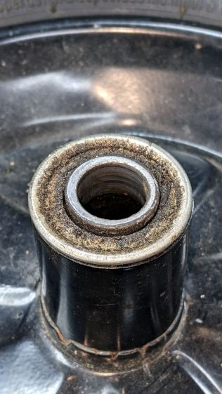
The rubber in pneumatic tires / tubes rots when left out in the open for a year or three, so I volunteered to replace the dead-flat tire (on the wheelbarrow I rebuilt last year) with the “flat free” solid foam tire+wheel harvested from an irreparably damaged wheelbarrow. Which, as it turned out, had lost one bearing and the remaining bearing wasn’t in good shape:
Wheelbarrow Wheel – victim bearing
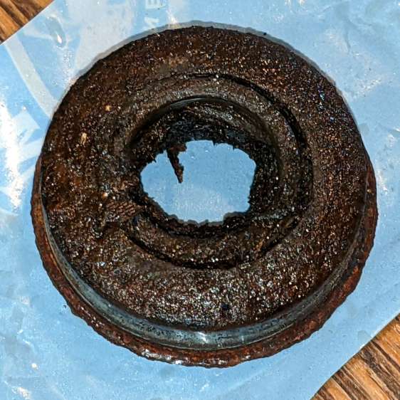
The bearings in the pneumatic wheel were in comparatively good shape:
Wheelbarrow Wheel – donor bearing
So I knocked the good bearings out, cleaned up / re-lubed them with squirts from my lifetime supply of genuine Mobil Vactra No. 2Sticky Way Oil, and hammered tapped them into the solid-tire wheel.
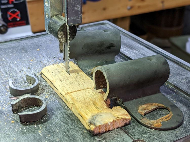
Whereupon I discovered the two wheels have different hub lengths and, unfortunately, the axle clamps in the recipient wheelbarrow lacked enough adjustment range.
Well, I can fix that:
Wheelbarrow Wheel – axle clamp cutting
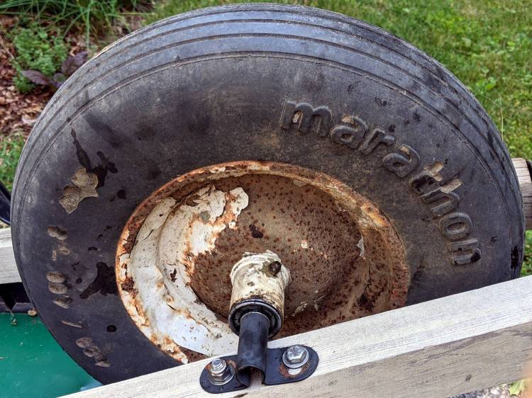
I briefly considered cleaning and repainting the wheel, but came to my senses when I considered the tire’s condition:
Wheelbarrow Wheel – transplanted
I suppose when the tread flakes off, the interior foam will rapidly erode, but we’ll burn that bridge when we encounter it.
The alert reader will have immediately noted the grease fitting on that rusty wheel: you’re supposed to periodically fill the entire hub with sufficient grease to push the crud out of the bearings. IMO, that’s so deep in silk purse territory as to be irrelevant.
The remaining useful parts from the defunct wheelbarrow will, most likely, come to good use next year …
Before trying to make decorative coasters from colorful acrylic, I figured a few practice sessions in chipboard would be in order:
Chipboard coasters
They’re colored with wide tip Sharpies of various ages and, as the yellow and uncolored sections show, chipboard never gets very bright. On the other paw, chipboard is also known as “beer mat”, so at least I have the right general idea.
The patterns come from a GCMC program producing SVG figures for LightBurn to apply kerf compensation:
Chipboard coasters – cut and color
It’s obviously too late to have me color within the lines.
The overall frame in the upper left and the base plate in the upper right get the kerf compensation, which (for chipboard) turns out to be +0.15 mm outward (thus making the holes smaller and the diameter larger). If I were doing marquetry, I’d want to arrange each piece on a separate wood veneer sheet with proper grain orientation and similar fussiness, but that’s not the point right now.
Without compensation, the pieces have a drop-in fit with an obvious gap:
Coaster – chipboard – no kerf comp
Adding a mere 0.15 mm on each side produces a very snug fit:
Coaster – chipboard – frame 0.15 out
In fact, the pieces go in from the back and require hammering gentle tapping to persuade all the corners into place.
Protip: putting a dark color on the frame and around the edges conceals many flaws.
Increasing the compensation to +0.20 mm means the pieces no longer fit and, when eventually battered into the frame, the surface becomes a concave-upward dish.
With the (colored) pieces in the frame, I covered the base plate with a thin layer of good old Elmer’s Yellow Wood Glue, dropped the top over it with some attention to good alignment on all sides, and clamped the assembly between two planks for a while. Obviously, you’d want to make more than one at a time, but they’re rather labor intensive.
The GCMC program produces the patterns from the coaster’s dimensions:
Outer diameter
Number of leaves around the center
Center spot diameter
Sash width (it’s really a muntin, but quilters say sash)
Leaf aspect ratio (max width / overall length)
Due to the relentless symmetry, finding the points describing half a leaf and half the sector between two leaves suffices to generate the entire coaster by various rotations around the center. The code performs no error checking whatsoever, so some dimensions emit a hard crash rather than a coaster.
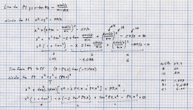
A geometry doodle with some incorrect values:
Coaster Geometry doodle
Poinr P1 (where the leaf snugs against the circular sash around the center spot) sits at the intersection of a line and a circle, so the code solves a quadratic equation with grisly coefficients:
  a = 1 + pow(tan(LeafStemHA),2);
  b = -2 * tan(LeafStemHA) * (Sash/2) / cos(LeafStemHA);
  c = pow((Sash/2) / cos(LeafStemHA),2) - pow(LeafID/2,2);
  xp = (-b + sqrt(pow(b,2) - 4*a*c))/(2*a);
  xn = (-b - sqrt(pow(b,2) - 4*a*c))/(2*a);
  y = xp*tan(LeafStemHA) - (Sash/2) / cos(LeafStemHA);
  P1 = [xp,y];
Given the geometry, the “plus” root is always the one to use.
A doodle working out that intersection, as well as for P5 out at the widest part of the leaf, carrying some errors from the geometry doodle:
Coaster Geometry equations
Both of those doodles have errors; the GCMC source code remains the final arbiter of coaster correctness.
This file contains hidden or bidirectional Unicode text that may be interpreted or compiled differently than what appears below. To review, open the file in an editor that reveals hidden Unicode characters.
Learn more about bidirectional Unicode characters
This file contains hidden or bidirectional Unicode text that may be interpreted or compiled differently than what appears below. To review, open the file in an editor that reveals hidden Unicode characters.
Learn more about bidirectional Unicode characters
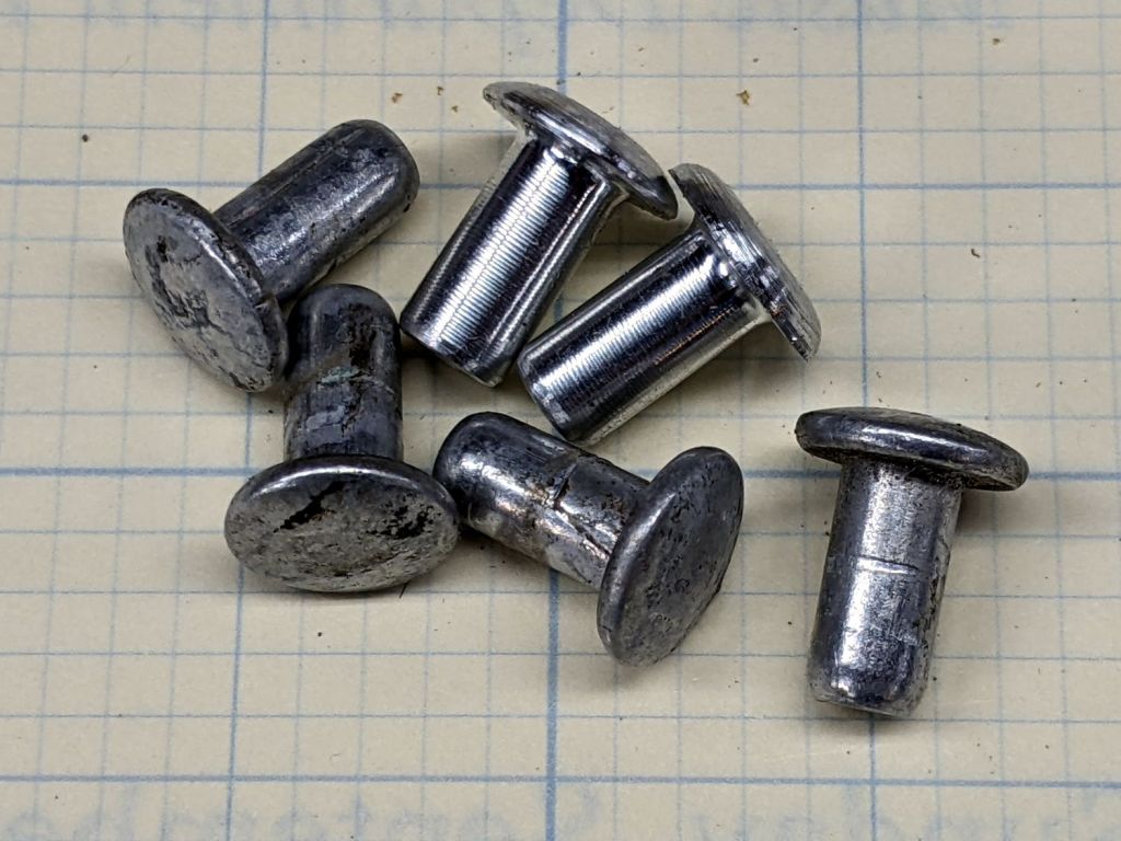
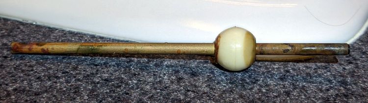
I planned to replace the vinyl straps on our set of (salvaged) lawn / patio chairs and made a pair of rivets for one long-missing strap:
Lawn chair strap rivets
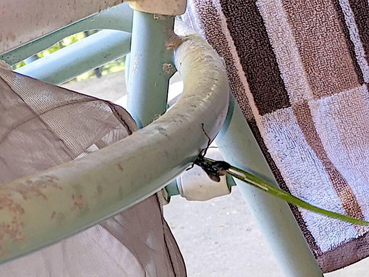
The overall project is on indefinite hold, as a Steel-blue Cricket Hunter (*) has decided at least one of the chairs is an ideal place to start a family:
Lawn chair – wasp nest under construction
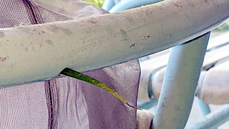
The patio under the chair is littered with blades of grass and twigs that didn’t quite fit through the 5 mm vent hole in the tube, but that long stem went in just fine:
Lawn chair – wasp nest grass stem
We have seen the wasp airlifting crickets near the chair, so provisioning has begun. The cricket seemed not only larger than the hole, but also larger than the wasp; we assume the wasp knows what she’s doing.
The new wasp will hatch this year, pupate over the winter, then hatch and emerge next summer, but I plan to replace the straps after the construction season ends.
I have no idea how to clean out whatever’s accumulating in there …
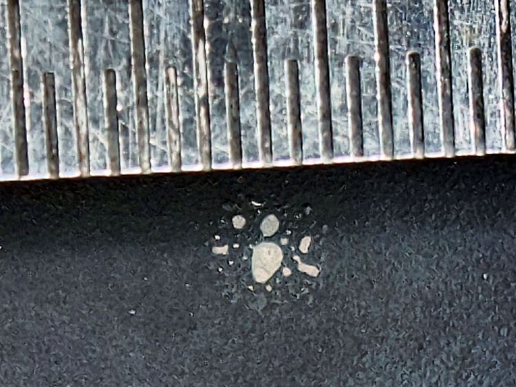
(*) I learned them as Steel-blue Cricket Killer, but the crickets are just paralyzed, not completely dead.
The 0.5 mm scale suggests the damage came from a defocused 2 mm beam or the hot central part of a larger beam, but I obviously wasn’t paying enough attention at the time.
The rest of the surface seems undamaged, so this may have been one of those inadvertent long-duration pulses or several shorter shots in one spot.
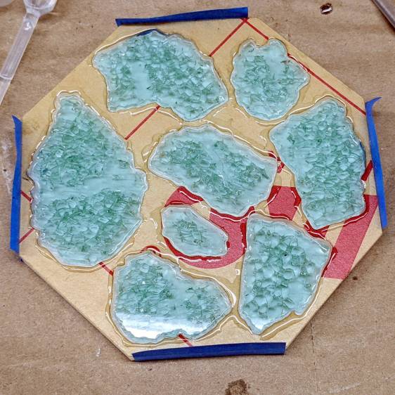
So, back to the Basement Shop, where a laser-cut and -engraved layout guide helps arrange and carry some suitable fragments:
Glass Coaster – Layout tray
As before, scan the bottom of the fragments and wrap selections around them:
Coaster Layout – selected fragments
Apply the usual operations to get a suitable mask:
Coaster Layout – fragment masks
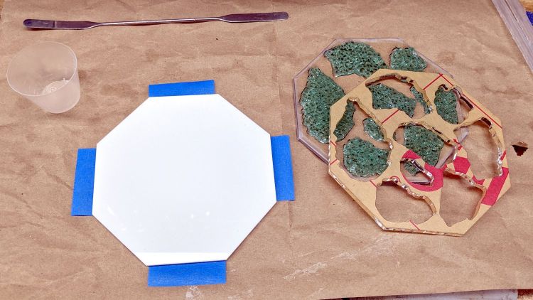
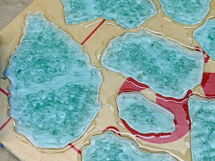
Fire the laser to cut the chipboard test template holding the fragments, then a white octagonal acrylic base plate and a transparent acrylic layer surrounding the fragments, and:
Glass Coaster – base epoxy setup
Mix up some pourable epoxy, smooth it over the base plate, squish the transparent layer atop it, use the tape (sticky side up) to hold the two layers in alignment, and gently insert the fragments:
Glass Coaster – fragment epoxy
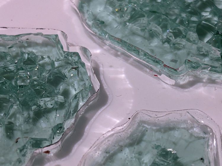
I eased some epoxy around the perimeter of each fragment with a pipette in an attempt to reduce the glass-sliver hazard:
Glass Coaster – fragment epoxy detail
Yes, that’s on top of the protective paper, because then I can whisk the paper off to reveal the pristine surface around each fragment:
Glass Coaster – fracture filling
As with the smaller coaster, the epoxy penetrates the fractures and reduces the shattered appearance. Mary suggests tinted epoxy would produce an interesting effect and I’ll try that the next time around.
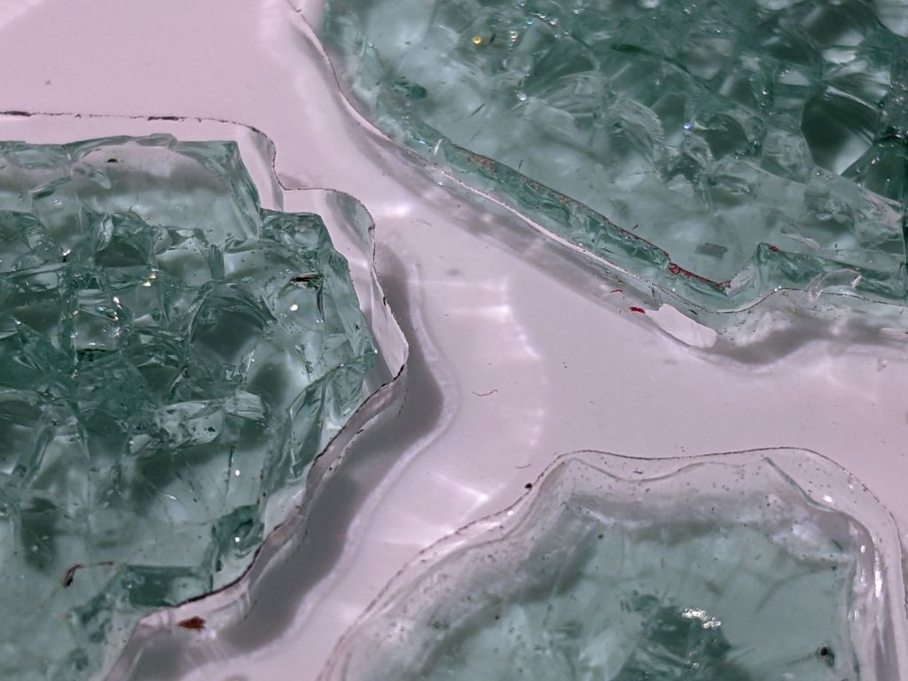
Seen through the edge of the coaster, the uneven surface of the epoxy fill around the fragments shows up clearly:
Glass Coaster – fragment edge profile
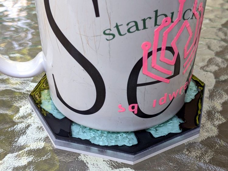
The top of the glass stands half a millimeter above the transparent acrylic. I knew that would happen and wanted to see how the bottom of the mug interacted with the epoxy-coated sides:
Glass Coaster – first test
As it turned out, the epoxy coating wasn’t quite good enough to prevent tiny slivers from chipping off and, in the cold light of day, the pale-green-ish tinted glass didn’t stand out well against the white background.
So I taped up the perimeter, leveled the base, mixed up another batch of epoxy, added two drops of opaque black dye, and poured just enough to level the surface with the glass:
Glass Coaster – black epoxy pour
Introducing the meniscus to Mr Belt Sander put a bevel around the edge and finished it off well enough:
Glass Coaster – second test
The Squidwrench logo looks a bit battered after three and a half years of trips through the dishwasher, although I didn’t expect it to last nearly this long.
There’s still a slight upward tilt around the perimeter, but it meets my simple requirements and the fragments definitely look better in black. The white base sets off the fragments, but a clear plate takes advantage of their transparency; a mirror sheet might be even more interesting.
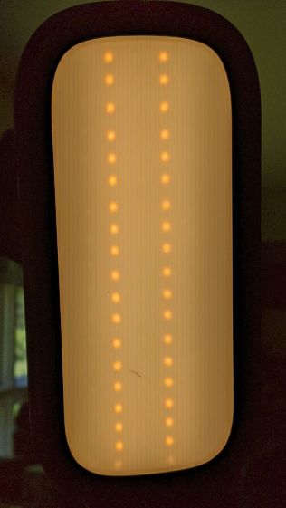
The only LED floor lamp I bought which didn’t require extensive hackery to lower the business end to suit Mary’s preferences failed after two years. The warm white LEDs continued to work fine:
Miroco LED Floor Lamp – warm white LEDs
But the cool white LEDs were permanently on at a very low level and did not respond to any of the brightness controls:
Miroco LED Floor Lamp – cool white LEDs
You can’t tell, but the cool whites are on in the first picture, too.
The symptoms suggested the driver transistor for the cool whites has failed partially on, although I’d expect it to be either a dead short or completely open.
The lamp being a year or more out of warranty and having come from one of the myriad Amazon sellers banned during the Great Paid Review Purge, there’s nothing to do but remove the four screws from the back of the control lump and see what’s inside:
Miroco LED Floor Lamp – PCB packing
How this was assembled I cannot say, because the three wires going to the LED head (on the far right) have less than an inch of slack. Maybe they pulled wire into the head while screwing things together?
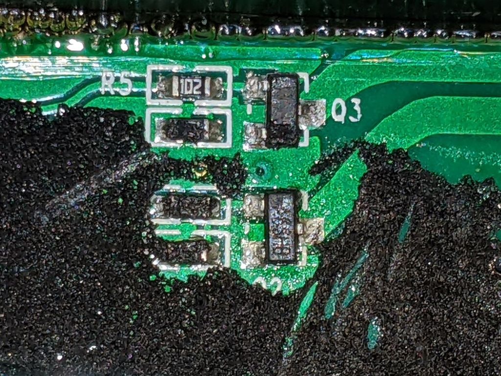
I think the HC8T1212 microcontroller sticking out of the foam is a distant descendant of the Motorola (remember Motorola?) MC68HC05 family. I’m mildly surprised they didn’t use a 32-bit ARM / MIPS / whatever micro, with WiFi capability and a strong desire to siphon my private bits.
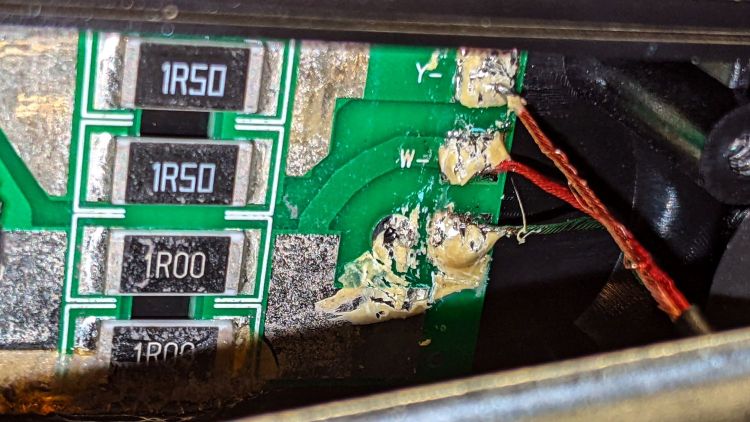
The two pieces of closed-cell foam seemed firmly glued to the PCB, but eventually yielded to brute force. Scraping brittle yellowish goo off the right end revealed the LED ballast resistors and the wire labels:
Miroco LED Floor Lamp – ballast resistors – LED wiring
Note the bar-taut Y- wire going to the warm-white (“yellow”?) LEDs.
The black foam left a mess over most of the PCB, but diligent scraping eventually revealed the driver transistors:
Miroco LED Floor Lamp – A6SHB MOSFETs
You can’t read it, but the topmarks were A6SHB: an old Siliconix (remember Siliconix?) SI2306 30 V / 3 A MOSFET. Turns out you can get new-production SI2306 transistors from the usual Asian foundries through eBay, which I did.
It’s not the neatest soldering job ever, but it’ll suffice:
Miroco LED Floor Lamp – A6SHB MOSFET replaced
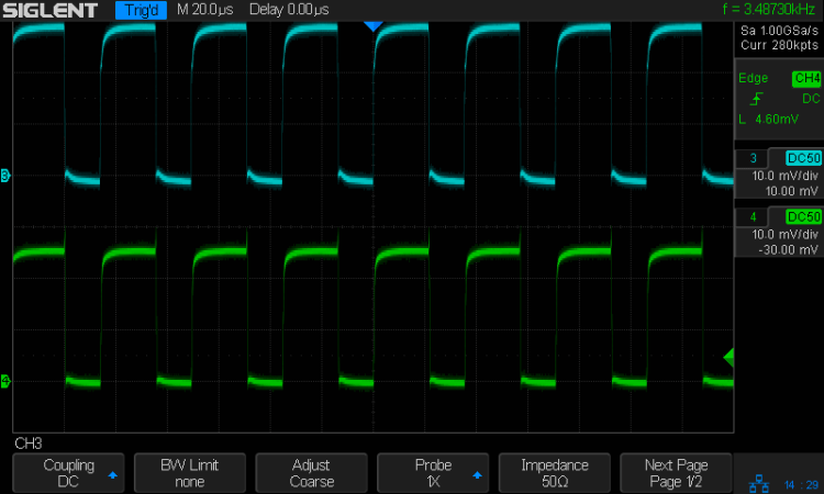
The colorful wires over on the right added enough length for a pair of Tek current probes:
Miroco LED Floor Lamp – 200 mA-div
The top (cyan) trace is the (repaired) cool LEDs, drawing 600 mA from the 10 V supply, so the 0.5 Ω ballast dissipates 180 mW. The bottom (green) trace is the warm LEDs at 500 mA through a 0.75 Ω ballast for 190 mW. That end of the control lump does feel a bit warm after a while, but nothing out of the ordinary.
Stuff the foam back in place, tuck the longer wires around the edges, snap the cover in place, reinstall the screws, and the lamp is at least as good as new.