Ed Nisley's Blog: Shop notes, electronics, firmware, machinery, 3D printing, laser cuttery, and curiosities. Contents: 100% human thinking, 0% AI slop.
For reasons not relevant here, a new medication has entered the house, accompanied by its Drug Fact Sheet (blurred because you do not have a Need To Know):
Drug Fact Sheet
The background squares are a scant one foot across.
The other side of the sheet is equally dense.
One should review this with each refill to check for new or changed information. Of course, there are no change bars or similar hints.
It might kill ya or cure ya, but you’ll never figure it out from that torrent of verbiage: just like software EULAs, nobody can possibly read and comprehend that stuff.
It’s easy to find the two front screws holding the top in place, although you’ll need either a bendy or offset screwdriver to remove them:
Sears Progressive Vacuum – front case screws
Pull up hard on the cord retraction plunger to remove it, revealing the two rear screws:
Sears Progressive Vacuum – rear case screws
Extract the wires and motor control PCB from their niches:
Sears Progressive Vacuum – motor assembly overview
Prying the latch in the middle of the rear panel (over on the right) releases the motor assembly, which you can then wiggle-n-jiggle upward and out:
Sears Progressive Vacuum – extracting motor assembly
Disconnect the wires, peel off various foam bits, and extract the motor from its carapace. Measure the blower diameter and cut a suitable plywood clamp for the bench vise:
Sears Progressive Vacuum – custom motor clamp
I loves me some good laser cutter action, even when the plywood crate the laser came in doesn’t have much to recommend it:
Sears Progressive Vacuum – failed plywood clamp
I vaguely recall reading the purple tinge comes from the bromine vapor used to dis-insect the wood during manufacturing, before shipping it halfway around the planet.
One area of the commutator looks like it’s in bad shape:
Sears Progressive Vacuum – as-found commutator
Clean the commutator bars in the desperate hope it’s just random crud, even though that seems unlikely, then connect a widowmaker cord to the motor terminals:
Sears Progressive Vacuum – widowmaker line cord
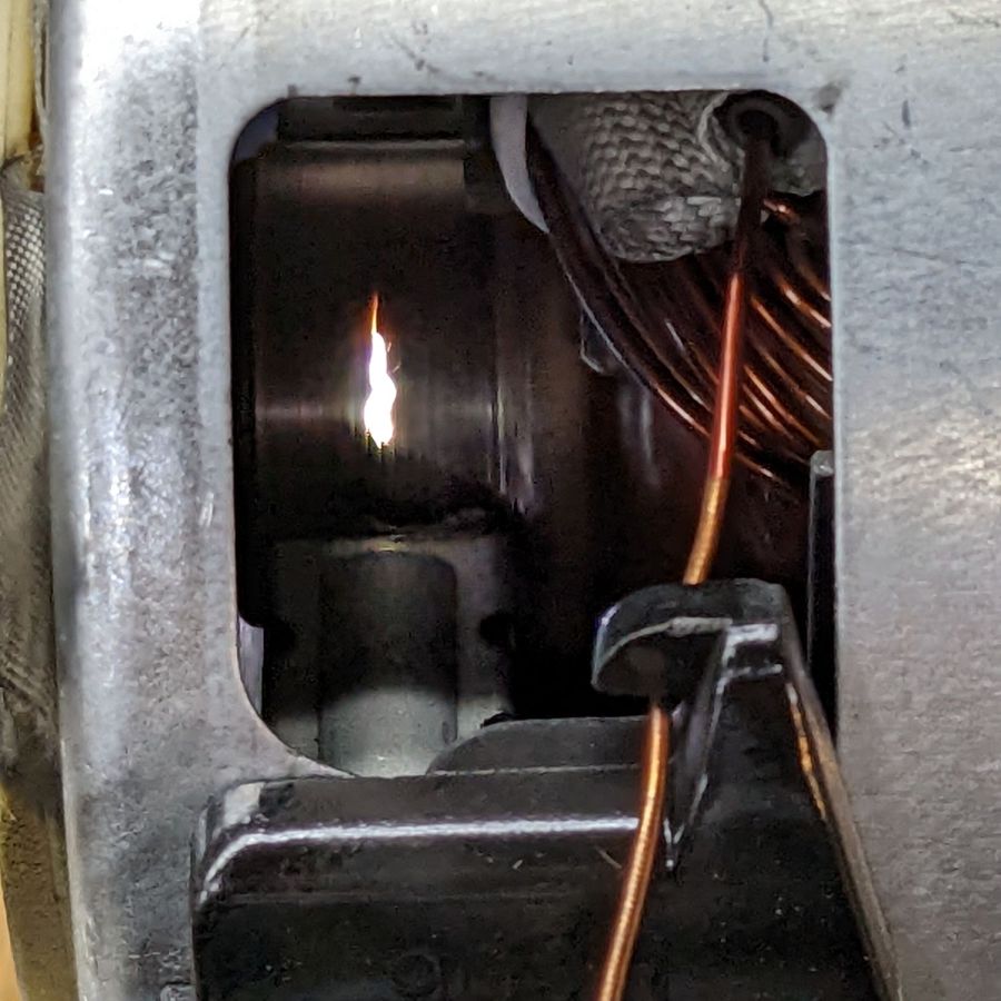
Use a Variac to spin the motor at a (relatively) low speed while watching the brushes and commutator:
Sears Progressive Vacuum – commutator sparking
Now, that is not a nominal outcome.
The cleaned commutator again shows signs of distress:
Sears Progressive Vacuum – scarred commutator
Indeed, measuring the resistance across the line cord terminals shows a shorted winding: 0.0 Ω with the brushes aligned on the bars just antispinward of the scars.
So the motor is definitely, irretrievably dead.
Extracting the brushes shows the arcs have eroded their spinward edges:
Sears Progressive Vacuum – eroded motor brushes
The dark smudge on the windings seems due to internal problems, rather than just the arcs, because the wiring crossing between the commutator and the smudge remains clean:
Sears Progressive Vacuum – charred motor windings
One can buy a used motor assembly on eBay for about $40, with no assurance it doesn’t also have a shorted winding.
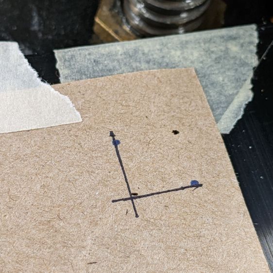
Burn some holes and draw lines 10 mm in from the physical corners, like this:
LB Camera Cal – corner target
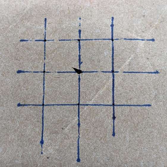
Burn holes and lay in a 10 mm grid at the center point:
LB Camera Cal – center grid
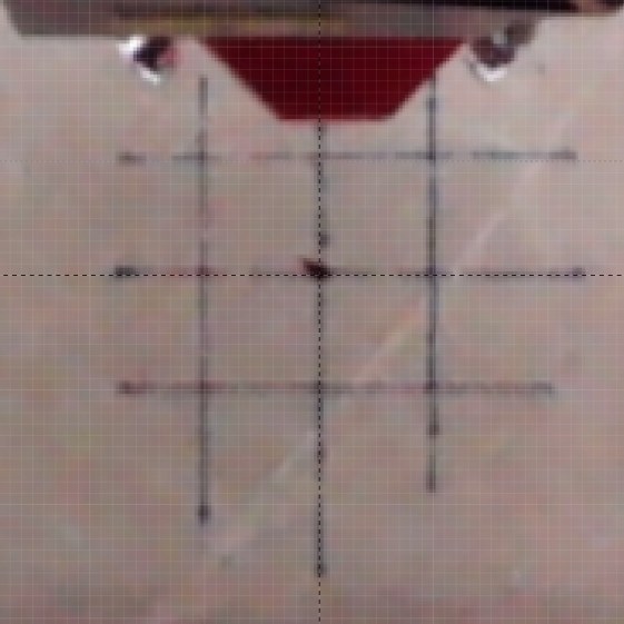
The center grid as seen through the camera:
LB Camera Cal – center grid overlay
That’s after adjusting the X and Y offset to align the center of the imaged grid with the center of the design grid. That’s using the non-faded image to make the target lines more visible.
The corner markers don’t quite line up with the grid, but they’re not off by much (using the faded image to make the grid more visible):
You could, of course, split the difference among all five sites, but I think having the middle of the platform be more accurate than the far corners makes more sense.
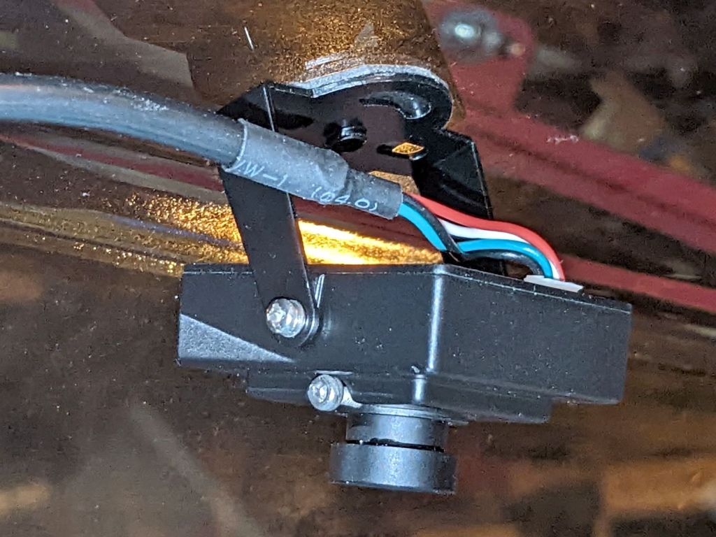
Early on, I stuck a camera to the lid of my OMTech 60 W laser:
OMTech Laser – camera mount
The uncorrected view from the camera (through VLC):
LB Uncorrected Camera View
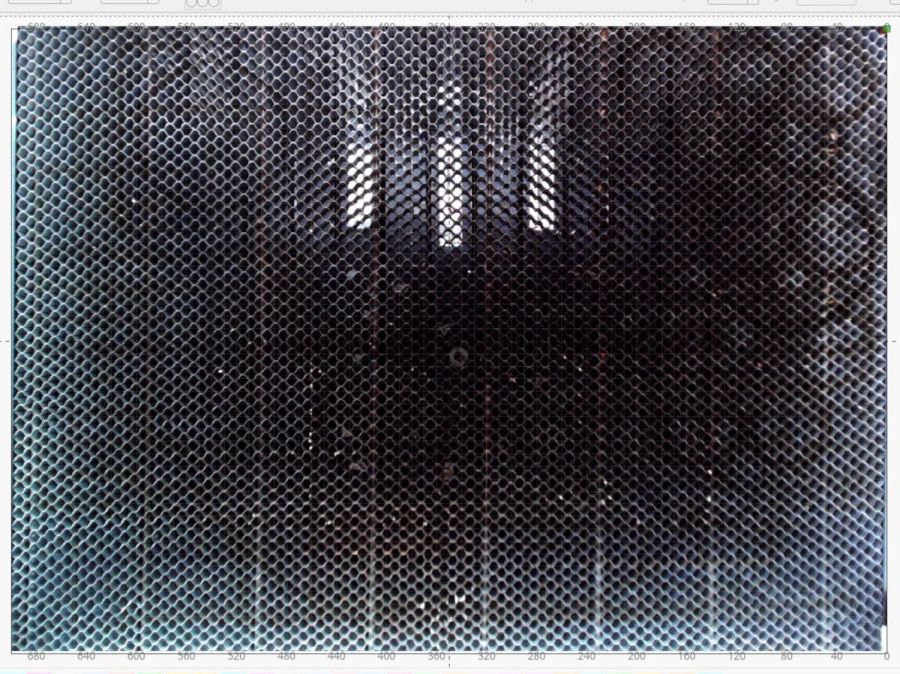
After calibration and alignment, LightBurn underlays this view of the platform behind the workspace:
LB Corrected Camera View
The correction depends critically on the camera maintaining its position / orientation / focus, which turns out to be a bad assumption for the camera I’ve been using, because the (metal) focus locking screw binds directly on the (metal) lens threads. This works, until vibrations slightly loosen the screw and the lens shifts ever so slightly.
After noticing the focus had shifted again, I tucked a snippet of silicone insulation from some 30 AWG hookup wire into the screw hole to compress against the lens thread, then re-did the entire sequence with some attention to detail.
Pulsing the laser in each corner produced pinholes exactly 700×500 mm apart. One diagonal is 859.0 mm and the other is 861.5 mm, pretty close to the ideal 860.2 mm.
Next, to measure the offsets from some known positions …
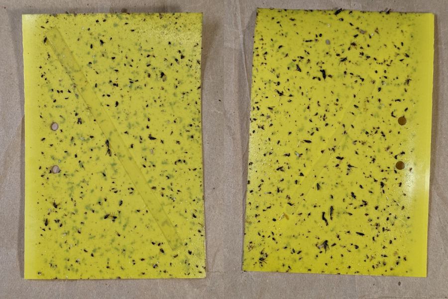
Mary left the sticky card traps in the onion patch until the last onions came out, clustered them around the leeks, and collected them long after the season was over.
I count maybe twenty flies that might be onion maggot flies or cabbage maggot flies.
The cards protected the onion crop, failed miserably for the leeks, and did nothing for the nearby cabbages. Deploying the cards while planting worked very well, refreshing them after a month continued the protection, but the main fly season seems to end shortly thereafter.
All the sticky cards as a slideshow, starting with the three along the border fence:
VCCG Onion Card – fence A – 2022-11
VCCG Onion Card – fence B – 2022-11
VCCG Onion Card – fence C – 2022-11
VCCG Onion Card – plot A – 2022-11
VCCG Onion Card – plot B – 2022-11
VCCG Onion Card – plot C – 2022-11
VCCG Onion Card – plot D – 2022-11
The cards remain sticky to my fingers, but an adroit fly could skate over the debris field and emerge unscathed.
The Hakko FX-888 soldering iron perched on the corner of my bench has a little red LED that lights up when it’s heating and goes off when it’s not. Unfortunately, while shutting down after fixing something, I sometimes glance at the thing while the LED is off, whereupon it will patiently keep the iron hot, sometimes for days, until I return.
A recent Squidwrench session gave me the opportunity to yoink that nuisance off the to-do pile where it has been pending since about ten minutes after I unboxed the iron a decade ago.
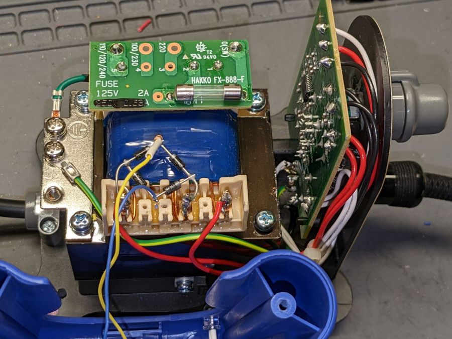
Some concerted rummaging failed to turn up the stash of bridge rectifiers, so I air-wired one from a quartet of discrete diodes:
Hakko 888 Soldering Iron pilot – bridge rectifier
Remember: the bigger the blob, the better the job.
For the record, the transformer produces 28 VAC, with the center tap 26 VAC from the left end and 2 VAC from the right end.
A 10 kΩ resistor stands upright at the far corner of the bridge, limiting the LED current to a few milliamps and making it bright enough for the purpose.
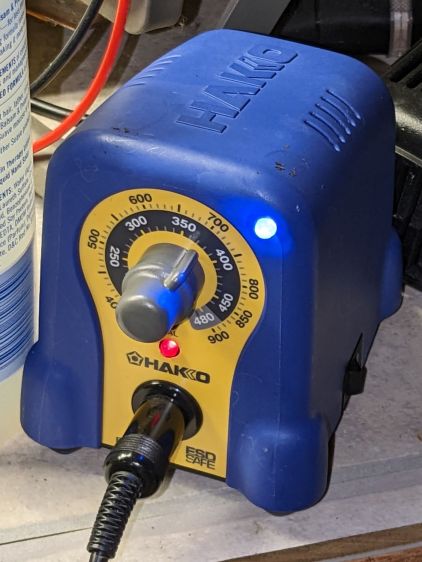
The front of the case has plenty of vacant space in its upper corners, so I drilled a hole and poked a blue LED:
Hakko 888 Soldering Iron pilot – heating
That’s shown with the iron heating.
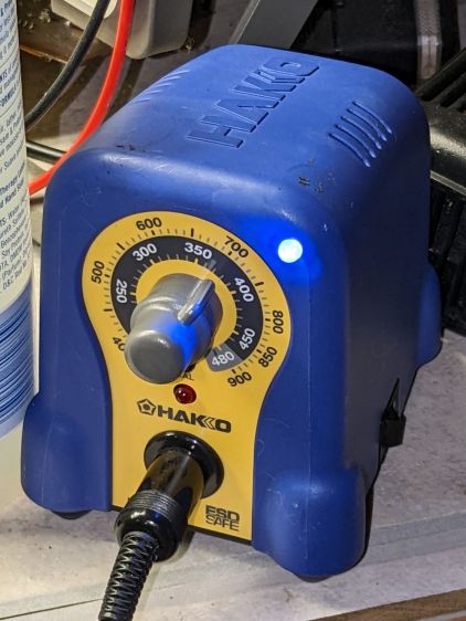
Here’s an action shot with the temperature at the setpoint:
Hakko 888 Soldering Iron pilot – stable
Nowadays all soldering irons have digital readouts with no need for a pilot light.
Of course, two days later I found the bridge rectifier stash, but there’s no point in opening the patient again.
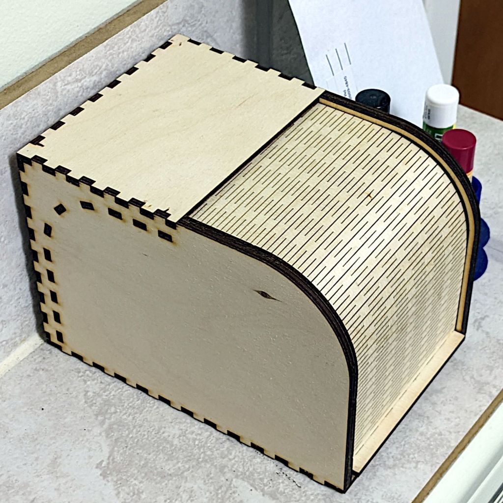
It’s actually the sample Bread Box, sized just about right for a cupcake or two:
Rolltop cupcake box – closed
Even if I have a soft spot for cupcakes, it’s also the right size to corral the batteries we use on the bikes:
Rolltop cupcake box – open
I’d never done anything with flexible plywood sheets, so I started by cutting the door all by itself. Turns out 3 mm plywood flexes wonderfully well, which led to cutting the rest of the box.
The zit on the left side is a knot on the “bad” side of the plywood, visible due to not reversing that piece to put its “good” side downward. I also had to re-cut the curved door guides along the front edge (using the paper support) after they fell through the stock (up on spikes) and got torched during subsequent cuts:
Rolltop cupcake box – cutting guides
The instructions recommend applying wax to the sliding surfaces and that’s a very good idea; although I used cutting wax, paraffin should work. In addition, I filed off the projecting edges of the guide plates around the interior curve, if only to be sure the door couldn’t possibly catch after it was permanently assembled.
I glued it in about five stages to keep everything aligned, starting with the right rear corner stabilized by the bench block and eventually coaxing the left side over all those fingers.