This should have been trivially easy and turned into a nightmare.
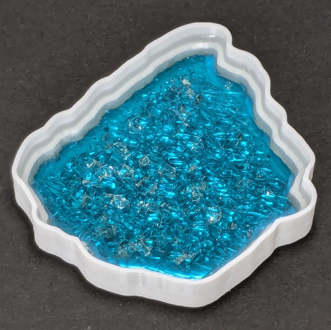
The problem to be solved is generating paths around fragments for the various recesses / reflectors / lips / rims / whatever. This clutter collector was a test piece:
The corresponding paths:
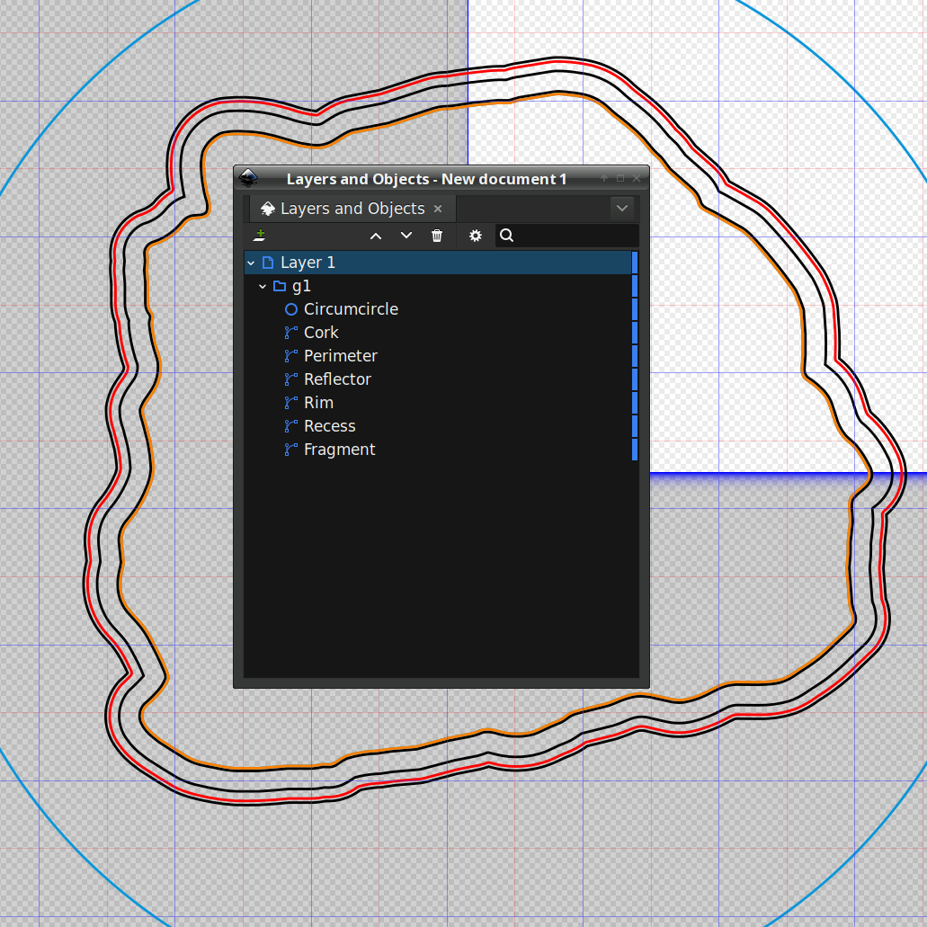
Which was how I convinced myself I didn’t need all those paths to make the thing, but that’s why it’s a test piece.
Anyhow, Inkscape has a remarkably complex and fiddly way of generating precise offsets:
- Select a path
- Hit
Ctrl-Jto create aDynamic Offsetpath - Drag the offset path away from the original in any direction for any distance
- Hit
Ctrl-Shift-xto fire up the XML editor (!) - Change the offset path’s
inkscape:radiusproperty to the desired offset
During the course of working that out, I discovered Inkscape 1.4.2 is incredibly crashy when creating and dealing with offsets, to the point that I simply gave up trying to do that.
LightBurn has no trouble creating a path at a specific offset from another path and can export the result as an SVG file. You then use Inkscape to set the path IDs so that OpenSCAD can import them by name for a specific use. Although Inkscape isn’t entirely stable doing even that seemingly trivial task, it’s usable.
For reasons I do not profess to understand, setting the name of a path sometimes does not set its ID property, which is required by OpenSCAD to extract it from the SVG file. Instead, you must verify / set the ID using the path’s Object Properties window:
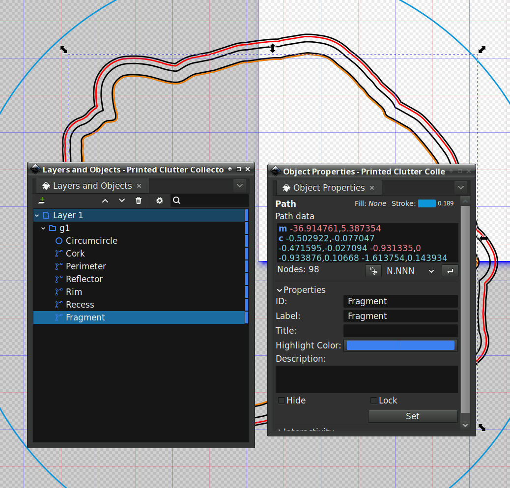
I also set the Label property, because … why not?
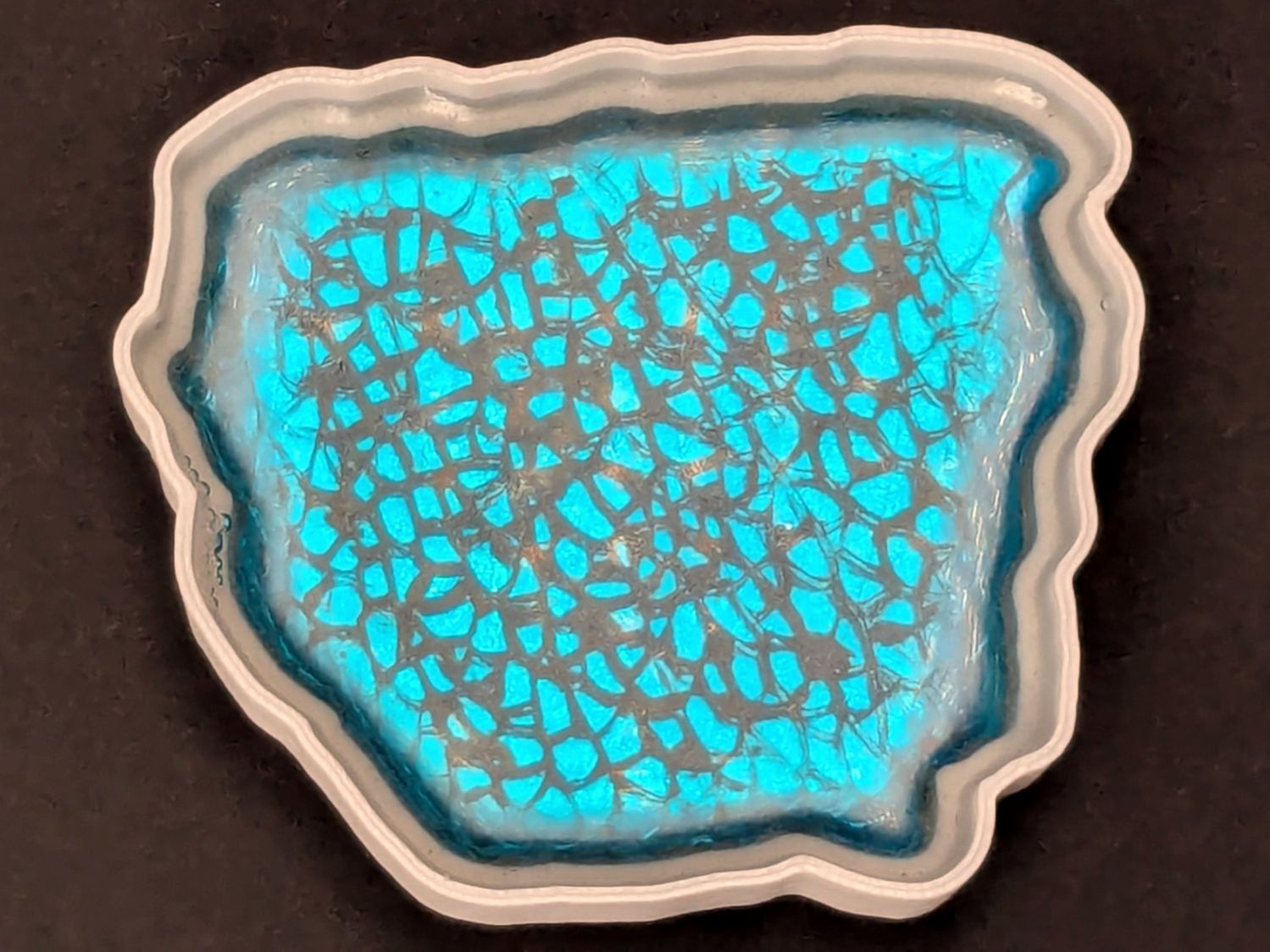
A top view shows how the various paths look in real life:
The OpenSCAD program generating the solid model from those paths:
include <BOSL2/std.scad>

fn = "Printed Clutter Collector - Inkscape layers.svg";

FragmentThick = 5.0;

BaseThick = 1.0;
RimHeight = 7.0;

union() {
  linear_extrude(h=BaseThick)
    import(fn,id="Perimeter");

  linear_extrude(h=BaseThick + FragmentThick + RimHeight)
    difference() {
      import(fn,id="Perimeter");
      import(fn,id="Rim");
    }

  up(BaseThick - 0.05)
    linear_extrude(h=FragmentThick)
      difference() {
        import(fn,id="Perimeter");
        import(fn,id="Recess");
      }

}
Which becomes this:
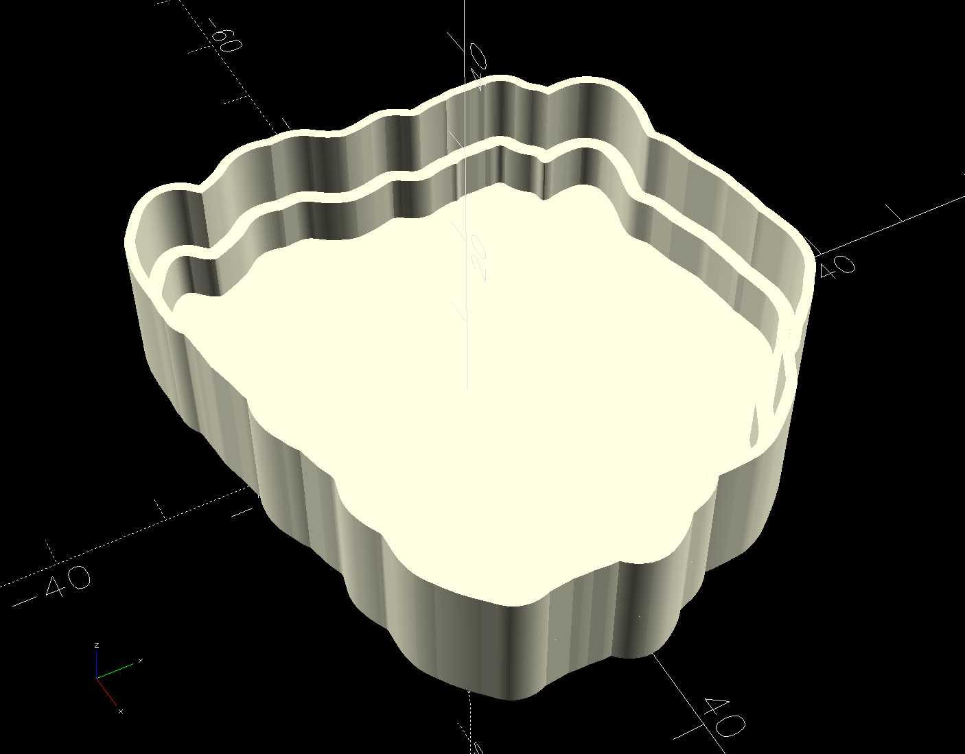
Save that, import it into PrusaSlicer, pick the filament, and print it out.
While the printer buzzes away, use LightBurn to cut a shiny blue metallized paper reflector and a cork base using the appropriate paths; presumably you set those paths to LightBurn layers corresponding to the various materials. The Inkscape file has those paths with their names, because … why not?
To assemble:
- Cover the bottom of the recess with epoxy
- Squish the reflector in place with epoxy oozing around it on all sides
- Cover the reflector with epoxy
- Squish the fragment atop the reflector with epoxy oozing around it on all sides
- Fill the recess level with the lip inside the perimeter wall
- Pop bubbles as needed
- When it’s cured, stick the cork sheet on the bottom
Note that the OpenSCAD program uses the path geometry without question, so it’s your responsibility to create them with the proper offsets and names.
While all of that to-ing and fro-ing works, in the sense that I did make a rather nice clutter collector, it’s entirely too complicated and fiddly to be useful. Instead, I can now generate a coaster from just the fragment outlines and the coaster’s outer perimeter, a straightforward process which requires a bit more explanation.

Comments
3 responses to “3D Printed Smashed Glass Coasters: Fragment Path Offsets, Complicated Version”
Might it be easier to use offset() in openscad rather than the offsets in inkscape? Then you just have to import the single outline!
Stay tuned! :grin:
I gotta write down all the dead ends so I won’t be tempted to make them ever again …
[…] than use Inkscape or LightBurn to generate all the offsets required to make a solid model, it’s easier to let OpenSCAD handle […]