We don’t know what the proper term might be for this part of the machine, but it looks sorta like a nose and the lights form most of a ring around it, so I’m going with “Nose Ring Lights”:
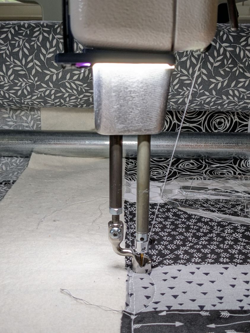
The general idea is to put more light on the quilt than the Chin Light, which looked pretty good until the COB LED strip started flickering as the LEDs failed.
Handi-Quilter sells a ring light for machines manufactured a decade later than ours, but it uses a built-in USB jack this machine lacks.
One of two (apparently) unused M4 holes on the left side of the machine frame suggested a mounting point for a 3D printed bracket:
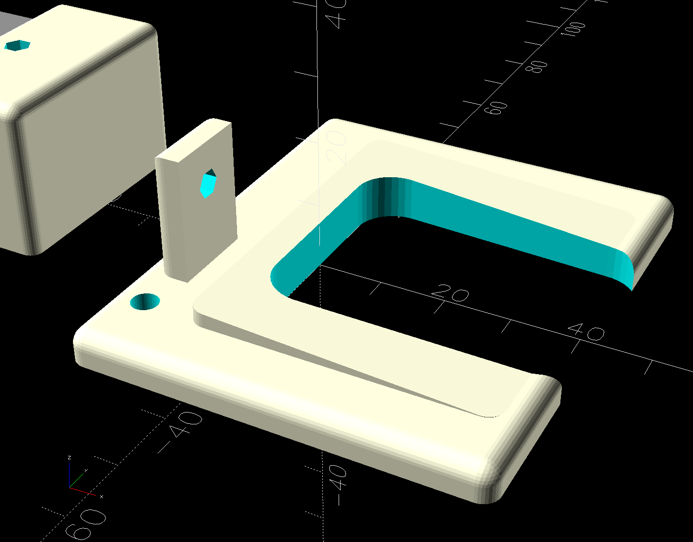
The ramp matches the 3° (-ish) mold draft of the machine frame, which I initially ignored by angling the tab, but a tilted frame looked awful; it’s now aligned with local horizontal..
A few iterations got all the pieces & holes in their proper places:
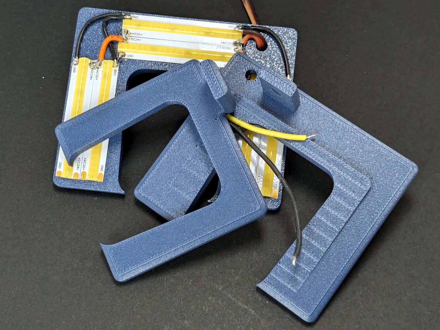
The smaller (rampless) bracket has three LED strips, but a quick test showed more light would be better:
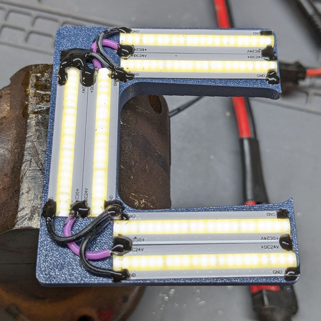
The lack of a transparent-ish cover is obviously unsuitable for a commercial product, but the key design goal is to not interfere with spreading as much light as possible across as much of the quilt as possible. The black JB Weld Plastic Bonder blobs keep the 24 VDC supply out of harm’s way, which is as good as it needs to be for now.
The bracket has three sides, because the right side of the machine has all the thread guide hardware. Putting anything over there seemed likely to interfere with either thread movement or fingers making adjustments.
Fortunately, the wider bracket doesn’t stick out too far beyond the machine frame and the doubled LED strips create a much smoother light pool:
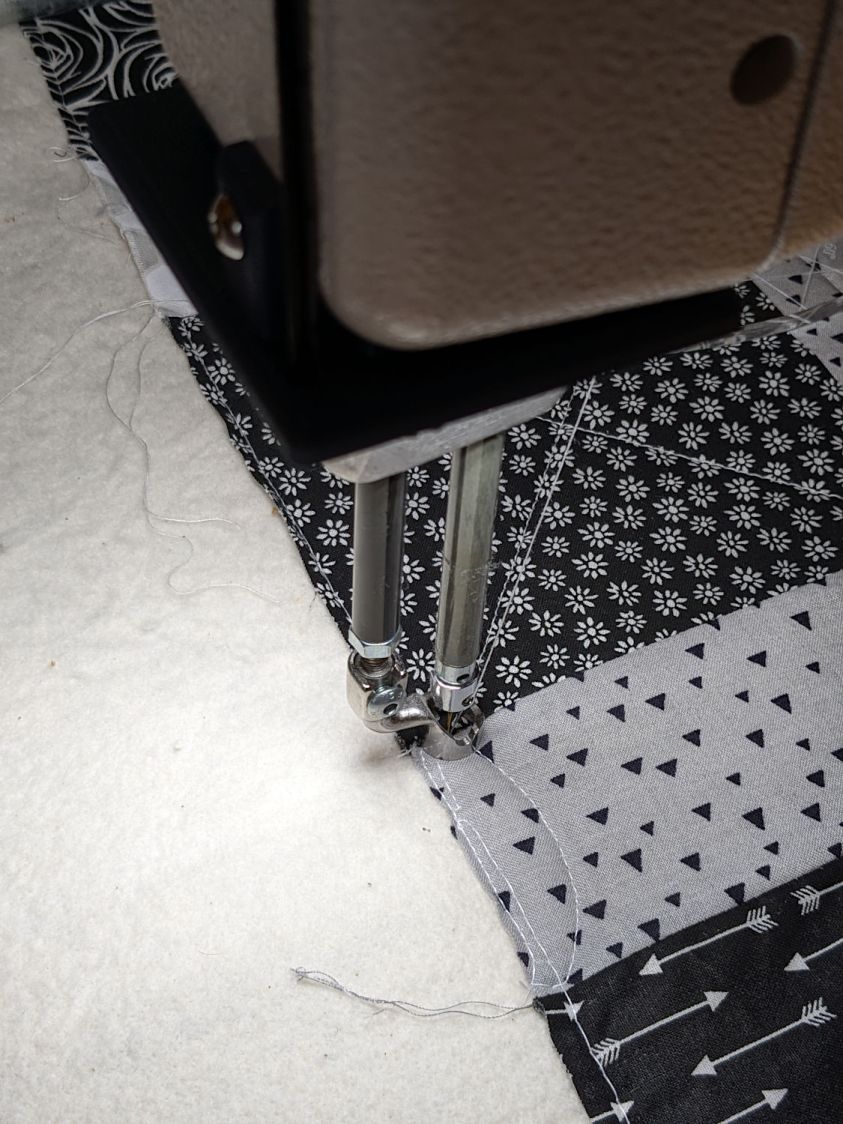
Yes, the quilt is focused and the LED frame is blurred.
The larger light-emitting area reduces the shadow under the left rod (supporting the ruler foot) enough to be unobjectionable.
A 0.2 mm layer thickness transforms the smooth ramp into stair steps:
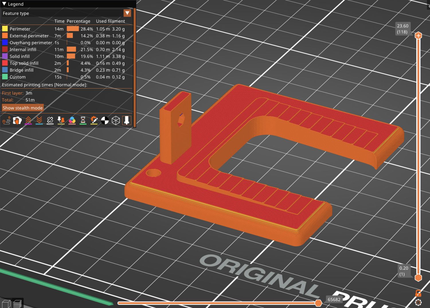
They’re inconspicuous after the bracket is installed.
The Chin Light ran on 12 V and these strips require 24 V, so the OpenSCAD code creates a pair of endcaps for the new supply, which is of course completely different than the old supply. Setting that up must await quilt completion.
The OpenSCAD source code as a GitHub Gist:
| // HQ Sixteen Nose Ring Lights | |
| // Ed Nisley – KE4ZNU | |
| // 2025-05-23 | |
| include <BOSL2/std.scad> | |
| Layout = "Show"; // [Show,Build,NosePlan,PowerCap] | |
| // Number of side-by-side LED strips | |
| Strips = 2; | |
| /* [Hidden] */ | |
| HoleWindage = 0.2; | |
| Protrusion = 0.1; | |
| NumSides = 3*3*4; | |
| $fn=NumSides; | |
| ID = 0; | |
| OD = 1; | |
| LENGTH = 2; | |
| Gap = 5.0; | |
| WallThick = 5.0; // default thickness for things | |
| NoseRadius = 6.0; // corner roundoff | |
| NoseOA = [44.0,36.5]; // overall nose size | |
| NoseAngles = [87,87]; // front & rear inward angles wrt left side | |
| NoseCenters = [ // centers of circles defining the nose corners | |
| [NoseRadius, NoseOA.y/2 – NoseRadius], | |
| [NoseRadius,-(NoseOA.y/2 – NoseRadius)], | |
| [NoseOA.x – NoseRadius, NoseOA.y/2 – NoseRadius – (NoseOA.x – 2*NoseRadius)*tan(90 – NoseAngles[0])], | |
| [NoseOA.x – NoseRadius,-(NoseOA.y/2 – NoseRadius – (NoseOA.x – 2*NoseRadius)*tan(90 – NoseAngles[1]))], | |
| ]; | |
| LEDMargin = 1.0; | |
| LEDStrip = [41.5 + LEDMargin,8.0 + LEDMargin,1.8 + 0.2]; // 24 V COB LED strip unit + windage | |
| LEDBaseOA = [LEDStrip.x + Strips*LEDStrip.y,NoseOA.y + 2*Strips*LEDStrip.y,WallThick]; // LED mount | |
| DraftAngle = 3.0; // angle of frame wrt horizontal at right end of nose | |
| DraftWedge = [NoseOA.x,NoseOA.y + 2*LEDStrip.y,NoseOA.x*tan(DraftAngle)]; | |
| HoleOffset = [-10.0,5.5,DraftWedge.z + 10.0]; // from left front corner of nose | |
| HolePosition = HoleOffset + [0,-NoseOA.y/2,WallThick]; // absolute coordinates from origin | |
| Screw = [4.0 + HoleWindage,9.0,2.0]; // LENGTH=button head | |
| Bracket = [WallThick,Screw[OD] + 4.0,HoleOffset.z + Screw[OD/2] + 2.0 + WallThick]; | |
| Supply = [46.0,30.0,21.0]; // 24 VDC power supply | |
| SupplyScrewOffset = 5.0; // … M4 screw hole from end of supply case | |
| CapWall = 3.0; | |
| CapRadius = CapWall – 1.0; | |
| CapInset = 1.0; | |
| CapOA = [20.0,Supply.y + 2*CapWall,Supply.z + CapWall]; // x & y to cover existing holes | |
| //———- | |
| // Define Shapes | |
| //—– 2D outline of nose piece just under frame casting | |
| module NosePlan() { | |
| hull() | |
| for (p = NoseCenters) | |
| translate(p) circle(r=NoseRadius); | |
| } | |
| //—– LED mounting plate | |
| module Mount() { | |
| union() { | |
| difference() { | |
| union() { | |
| right(LEDBaseOA.x/2 – Strips*LEDStrip.y) | |
| cuboid(LEDBaseOA,rounding=WallThick/2,except=BOTTOM,anchor=BOTTOM); | |
| up(LEDBaseOA.z) left(-HoleOffset.x/2) | |
| yrot(DraftAngle) | |
| cuboid(DraftWedge,rounding=WallThick/2,edges="Z",anchor=LEFT+BOTTOM); | |
| } | |
| down(Protrusion) | |
| linear_extrude(LEDBaseOA.z + DraftWedge.z + Protrusion) | |
| NosePlan(); | |
| if (Strips > 1) | |
| translate([HolePosition.x – Bracket.x/2,HolePosition.y – Bracket.y,-Protrusion]) | |
| cyl(LEDBaseOA.z + 2*Protrusion,d=4.0,anchor=BOTTOM); | |
| } | |
| difference() { | |
| union() { | |
| translate([HolePosition.x,HolePosition.y,(Bracket.x/2)*sin(DraftAngle)]) | |
| left(Bracket.x) | |
| cuboid(Bracket,rounding=WallThick/2,edges=LEFT,anchor=BOTTOM+LEFT); | |
| translate([HolePosition.x – Bracket.x/2,HolePosition.y,0]) // rounding filler | |
| cuboid([LEDStrip.y,Bracket.y,WallThick],anchor=BOTTOM+LEFT); | |
| } | |
| translate(HolePosition) | |
| xrot(180/6) xcyl(l=NoseOA.x,d=Screw[ID],$fn=6); | |
| } | |
| } | |
| } | |
| //—– Endcap for power supply | |
| module EndCap() { | |
| difference() { | |
| cuboid(CapOA,rounding=CapRadius,except=BOTTOM,anchor=LEFT+BOTTOM); | |
| right(CapOA.x – CapWall) down(Protrusion) | |
| cuboid(Supply + [0,0,Protrusion],anchor=RIGHT+BOTTOM); | |
| right(CapInset + SupplyScrewOffset) | |
| zcyl(l=2*CapOA.z,d=Screw[ID],$fn=6,anchor=BOTTOM); | |
| } | |
| } | |
| //———- | |
| // Build things | |
| if (Layout == "NosePlan") { | |
| NosePlan(); | |
| } | |
| if (Layout == "PowerCap") { | |
| EndCap(); | |
| } | |
| if (Layout == "Show") { | |
| Mount(); | |
| ctr = 80; | |
| ofs = Supply.x/2 – CapInset; | |
| left(ctr – ofs) | |
| EndCap(); | |
| left(ctr + ofs) | |
| xflip() | |
| EndCap(); | |
| color("Silver",0.6) | |
| left (ctr) | |
| cuboid(Supply,anchor=BOTTOM); | |
| } | |
| if (Layout == "Build") { | |
| Mount(); | |
| back((LEDBaseOA.y + CapOA.y)/2 + Gap) right(Gap) up(CapOA.z) zflip() | |
| EndCap(); | |
| back((LEDBaseOA.y + CapOA.y)/2 + Gap) left(Gap) zrot(180) up(CapOA.z) zflip() | |
| EndCap(); | |
| } |

Comments
5 responses to “HQ Sixteen: Nose Ring Lights”
To follow current industry practices, you should print proper heat-sink fins on this holder and then paint the whole thing in shiny aluminum color.
(Or black, black color apparently also creates a heat sink.)
Sort of like copper: conducts electrons better than gold when it’s plated on steel …
Ah, the famous magnetic copper!
I ran into that one as well. It is almost a feature. For a few mA over 4 inches it doesn’t matter much, but makes the cable more sturdy.
But the plastic heat sinks? Once you notice the magic plastic heat sinks, you see them everywhere: HDD adapters, bike lights, light bulbs. Even at LED lights they sell in big box stores.
Reminds me of an exchange I head with a Chinese seller:
Me: “Nice sewing, thread, but it isn’t cotton.”
Seller: “It is cotton.”
Me: “I really like the thread, it is perfect for sewing cotton, but you should fix the description.”
Seller: “It is cotton.”
Me: “But when I burn it, it melts.”
Seller: “Why would you do that!”
[…] With the quilt off the HQ Sixteen, I could install the 24 V power supply for the Nose Ring Lights: […]
[…] the nose ring lights in place, I soldered up eight more 24 V LED strips to light the quilt under the HQ Sixteen’s […]