A stack light above the laser cutter makes the controller’s input and output status easily visible:

Which will be especially valuable while I’m bypassing safety interlocks and poking around inside the cabinet.
The light is unavoidably upside-down from the industrial standard, because I can’t don’t want to mount it on the laser cabinet, and my use of color does not match the industrial convention. Neither of which matter for my simple needs.
In order from top to bottom:
- White = high flow assist air turned on
- Blue = chiller running, water flow / temperature good
- Green = controller running a job
- Orange = lid down
- Red = laser beam active
The blue and orange lights turn on when their inputs are active, so they positively show sensor satisfaction, rather than laser-disabling dissatisfaction. The entire stack lights up while the controller runs a job with assist air turned on, which is usually the case.
(See below for a slipstream update.)
The wiring diagram on the case is the only documentation enclosed with the stack light:
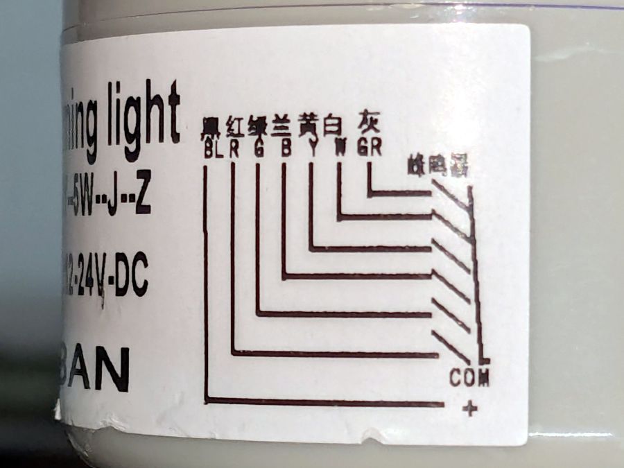
Any power supply between 12 VDC and 24 VDC will work and, contrary to the label, the COM lead can be either polarity: the light works in either common-anode or common-cathode configuration. Because the laser controller inputs and outputs are all low-active, I wired the COM terminal to +24 V, so pulling the other leads to GND turns on their lights.
The overall connection diagram, in order from easy to hard:

Some of the details behind the diagram explain what’s going on.

The water flow sensor is wired in series with the chiller, with a GND connection on the far end pulling the WP controller terminal low when both sensors are happy; the switches can handle another 50 mA of LED current with no problem.

The HV power supply has an internal pullup to +5 V on its L terminal, which means the L-ON output terminal sits at +5 V when the laser tube is off. Connecting the stack light directly to the L-ON terminal dumps the LED current into the 5 V supply through the pullup resistor, producing a somewhat weak glow in the LED when it should be off.
Running the optoisolator input from 5 V solves that problem, as its diode will be off when the L-ON output is high. When it’s low, the diode turns on, the isolator’s output transistors conduct, and the stack light gets the full 24 V it expects.
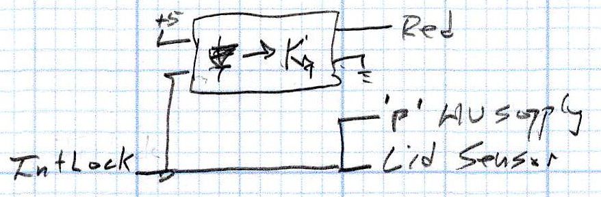
The lid sensor normally goes only to the IntLock controller terminal, but I also ran it to the otherwise unused P terminal on the HV power supply, in the possibly misguided belief it would prevent the supply from firing with the lid up if it failed like the first one. Those two inputs have 5 V pullups, so the optoisolator handles the stack light’s 24 V supply.

When I added the dual-path air assist plumbing, diode D1 turned on the air pump when either the Status or the AuxAir output turned on. When the job calls for assist air, the AuxAir output opens a valve to increase the air flow.
The Status output is active when the controller is running a job and that’s generally the only time the AuxAir output will be active, but the machine console has an Air button that manually activates it, so diode D2 isolates the Status output in that unusual situation.
Slipstream update: I realized swapping the green & orange lights would make more sense:
- White = high flow assist air turned on
- Blue = chiller running, water flow / temperature good
- Green = lid down
- Orange = controller running a job
- Red = laser beam active
Done!

Comments
4 responses to “Stack Light: Controller Wiring”
I was certain, I saw something similar at the dollar store :)
Well, they don’t have it right now, but sure enough, here it is:
https://www.aliexpress.us/item/3256807900408994.html
So many colors!
Laser cuttery / 3D printery / Arduino wiring would surely make it more wonderful! :grin:
Each part can be done more complicated of course: Instead of some simple chip an ESP flashed with tasmota and MQTT connection, instead of regular LEDs some WS2812 either on a strip or as individual 5mm LEDs, instead of normal wiring bare copper wires with LEDs soldered in between.
Just too bad dollartree doesn’t have it right now.
Ah, yes: Arduino is Old School. :grin: