After figuring out the Ruida focus settings, a focus ramp fixture seemed like a good thing to have around:
The solid model shows a bit more detail:

Centering the autofocus “pen” = switch on the peg in the back puts the beam dead-center in the fixture, with the notches as comfort marks. The top of the peg is flush with the center notch, so the machine should be properly focused at that level after a focus operation.
Obviously, your laser has a different pen location, as will this one the next time I fiddle with anything around the nozzle.
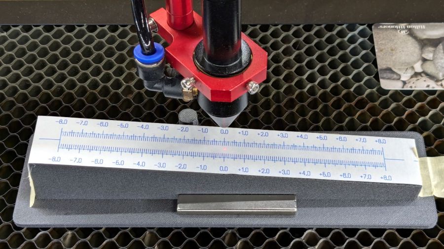
The general idea is to tape a target to the ramp, with some attention to flattening the paper (tape the edges in critical spots as needed) & putting its zero at the center marks, align the fixture to the laser path along the X axis & secure it with a few magnets, then burn a single line at low power along the length of the scale:

The mark will be thinnest in the region with the best focus, which should be centered around the 0.0 mark in the middle. In that photo, the thinnest section runs from about -2.0 to +1.0, although (at least for me) it does take some squinting to be sure.
The ramp has a 1:10 = 5.71° slope to spread 1 mm of vertical focus across 10 mm of horizontal distance. If you’re being finicky, you should rescale the targets to correct the 0.5% cosine error, but IMO it’s irrelevant for this purpose.
A few more tests varying the focus distance by a millimeter:
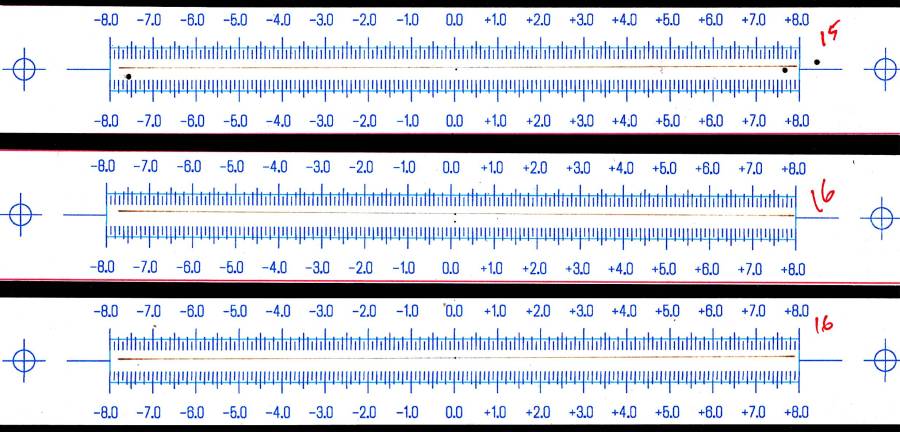
AFAICT, setting the controller’s Focus Distance to 16 mm is about right. That puts the focal point 18 mm below the nozzle, as shown in the earlier post, and is pretty much what I’ve been using all along.
The OpenSCAD code as a GitHub Gist, along with a simplified target layout in SVG format:
| // Laser Cutter Focus Ramp Fixture | |
| // Ed Nisley KE4ZNU | |
| // 2024-10-10 | |
| FocusPenOffset = [-19,23,0]; | |
| FocusPenOD = 10.0; | |
| RampHeight = 16.0; | |
| RampScale = 10; | |
| RampLength = RampScale * RampHeight; | |
| Magnet = [5.0,60.0,10.0]; | |
| NumSides = 3*4; | |
| Protrusion = 0.1; | |
| RampAngle = atan(RampHeight/RampLength); | |
| echo(RampAngle=RampAngle); | |
| Slot = [(RampLength + 2*5.0),10.0,8*RampHeight]; // very tall to cut through everything | |
| Body = [(Slot.x + 2*10.0),30.0,3*RampHeight]; // extend Z to reach baseplate | |
| FocusPillarHeight = (RampHeight/2) + Body.z/3; // match Z at center of body | |
| BasePlate = [(Body.x + 2*Magnet.x + 2*5.0),max(Magnet.y,FocusPenOffset.y + 2*5.0),3.0]; | |
| BaseRound = 5.0; | |
| //—– Build it | |
| difference() { | |
| union() { | |
| translate(FocusPenOffset) | |
| cylinder(d=FocusPenOD,h=FocusPillarHeight,$fn=NumSides); | |
| difference() { | |
| union() { | |
| rotate([0,RampAngle,0]) | |
| cube(Body,center=true); | |
| linear_extrude(height=BasePlate.z) | |
| hull() | |
| for (i=[-1,1], j=[-1,1]) | |
| translate([i*(BasePlate.x/2 – BaseRound),j*(BasePlate.y/2 – BaseRound)]) | |
| circle(r=BaseRound,$fn=NumSides); | |
| } | |
| cube(Slot,center=true); | |
| translate([0,0,FocusPillarHeight]) { | |
| cube([0.5,2*Body.y,1.0],center=true); | |
| rotate([0,RampAngle,0]) | |
| cube([2*Slot.x,0.5,1.0],center=true); | |
| } | |
| } | |
| } | |
| translate([0,0,-Body.z]) | |
| cube(2*[BasePlate.x,BasePlate.y,Body.z],center=true); | |
| } |
Contrary to what you might think, the targets are not laser cut, although you could use the crosshairs for LightBurn’s Print and Cut alignment.

Comments
3 responses to “Laser Cutter: Focus Ramp Fixture”
[…] few ramp tests with various Focus Distance + Home Offset settings as […]
[…] that in mind, though, I built the laser ramp focus fixture shortly after doing the first recalibration and it has no visible ripples on any of its […]
[…] the laser ramp test fixture looked good, Brent wondered what a real test box would reveal about the Prusa MK4’s Input […]