A protracted debugging session on the LightBurn forum produced an interest result, which I must yoink over here so I can recall my thoughts:
The test patterns will require power / speed tweakage to properly mark cardboard on other machines. The vector boxes are about 1.5 mm wide: these are small differences in small patterns.
The setup for both LightBurn 1.7 RC-13 and RDWorks 8.01.65:
- The engraved patterns run at 500 mm/s & 20% power
- The lines & letters run at 100 mm/s & 8% Min – 9% Max power
- All on white cardboard, with image contrast blown out
Scanning offset = 0.2 mm = the usual setting for my machine
In LightBurn:

In RDWorks:
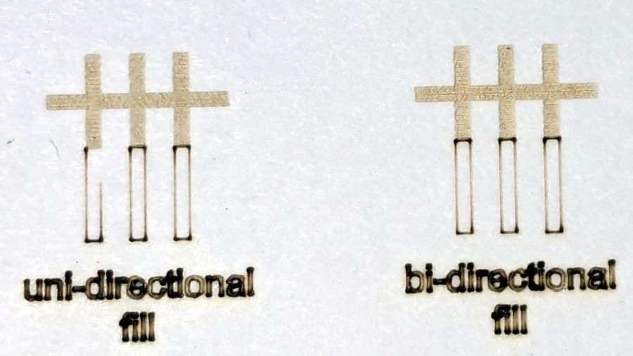
The slight shift to the left in the LightBurn results shows LB does not shift the uni-directional pattern to line up with the vector shape as RDWorks does, which is what started the forum thread.
Scanning offset = 1.0 mm to accentuate the difference, while shredding the bi-direction pattern as expected.
LightBurn’s uni-directional engraved pattern is still in the same slightly leftward-shifted position relative to the vectors, showing the offset value has not been applied:

RDWorks definitely applies the offset in both modes:

I do not know why RDWorks did not output the final “l” over there on the right, but it did so on some (not all) of the patterns while setting things up. The jank is strong with it.
So having LightBurn apply the same offset value for both uni- and bi-directional engravings would fix the (slight) offset in my machine. I think it will also fix the much larger misalignment in [the other] machine in that forum discussion.
The whole problem seems to arise from the response time of the HV power supply / laser tube: the position of the left & right edges of the scanned output line depend critically on the rising and falling edges of the current applied to the tube and its power output.
Being me, of course, makes me want a different offset value applied to the uni-directional case, just for fine tuning. Which would require a duplicate offset-per-speed table and that looks like a UX disaster comin’ on strong.
