The CNC-3018XL drawing the scales on a Tek Circuit Computer disagreed with the MPCNC cutting the perimeter. The Y axis edges looked OK:

But the cut on the X axis edges went too close to the tips:

I conjured a calibration target to help measure the two machines:

The X- side of the plot gives the general idea:

The vertical lines consist of two halves, drawn in order from left to right on the top and right to left on the bottom, meeting in the middle at the Y=0 axis. If they do, in fact, meet in the middle, then there’s no problem with backlash.
The 25 mm distance between adjacent lines verifies the linear calibration; the total distance along the X and Y axes provides more travel for more error accumulation.
The circles provide some reassurance the machine can draw a smooth circle, because they come from GRBL’s (or whatever) G2 G-Code commands, not a linear approximation.
Spoiler: after a considerable amount of drawing, measuring, and muttering, the problem emerged from the CNC-3018XL’s X-axis leadscrew:
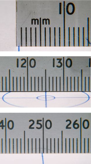
It’s half a millimeter short on each end!
More on this tomorrow …
The GCMC source code as a GitHub Gist:
| (epilog begins) | |
| (bCNC may regard plot as done before this returns) | |
| M2 | |
| (epilog ends) |
| (prolog begins) | |
| G17 (XY plane) | |
| G21 (mm) | |
| G40 (no cutter comp) | |
| G49 (no tool length comp) | |
| G80 (no motion mode) | |
| G90 (abs distance) | |
| G94 (units per minute) | |
| (prolog ends) |
| // Grid pattern to check XY scaling | |
| // Ed Nisley KE4ZNU – 2021-11 | |
| // gcmc -P 4 –pedantic –prolog prolog.gcmc –epilog epilog.gcmc –output 'Scale Grid.ngc' 'Scale Grid.gcmc' | |
| include("engrave.inc.gcmc"); | |
| FALSE = 0; | |
| TRUE = !FALSE; | |
| //—– | |
| // Define useful constants | |
| SafeZ = [-,-,10.0mm]; // above all obstructions | |
| TravelZ = [-,-,2.0mm]; // within engraving / milling area | |
| PenZ = [-,-,-1.0mm]; // depth for good inking | |
| PenSpeed = 2000mm; | |
| //—– | |
| // Overall values | |
| PlotSize = [250mm,200mm,-]; | |
| comment("PlotSize: ",PlotSize); | |
| GridSize = [25mm,25mm,-]; | |
| Margins = [5mm,5mm,-]; | |
| CenterOD = 5.0mm; | |
| TextFont = FONT_HSANS_1_RS; // single stroke stick font | |
| TextSize = 3.0 * [1.0mm,1.0mm]; | |
| //—– | |
| // Draw it | |
| feedrate(PenSpeed); | |
| comment("Draw title info"); | |
| tp = scale(typeset("Scale & Backlash Test Pattern",TextFont),TextSize); | |
| tp += [-PlotSize.x/2 + GridSize.x/2,PlotSize.y/2 – GridSize.y/2,-]; | |
| engrave(tp,TravelZ.z,PenZ.z); | |
| tp = scale(typeset("Grid " + GridSize,TextFont),TextSize); | |
| tp += [-PlotSize.x/2 + GridSize.x/2,PlotSize.y/2 – GridSize.y/2 – 1.5*TextSize.y,-]; | |
| engrave(tp,TravelZ.z,PenZ.z); | |
| tp = scale(typeset("F " + PenSpeed + "/min",TextFont),TextSize); | |
| tp += [-PlotSize.x/2 + GridSize.x/2,PlotSize.y/2 – GridSize.y/2 – 3.0*TextSize.y,-]; | |
| engrave(tp,TravelZ.z,PenZ.z); | |
| tp = scale(typeset("Ed Nisley – KE4ZNU",TextFont),TextSize); | |
| tp += [-PlotSize.x/2 + GridSize.x/2,-(PlotSize.y/2 – GridSize.y/2),-]; | |
| engrave(tp,TravelZ.z,PenZ.z); | |
| tp = scale(typeset("softsolder.com",TextFont),TextSize); | |
| tp += [-PlotSize.x/2 + GridSize.x/2,-(PlotSize.y/2 – GridSize.y/2 + 1.5*TextSize.y),-]; | |
| engrave(tp,TravelZ.z,PenZ.z); | |
| comment("Mark center point"); | |
| goto(SafeZ); | |
| goto([CenterOD/2,0,-]); | |
| move(PenZ); | |
| circle_cw([0,0]); | |
| comment("Label axes"); | |
| tp = scale(typeset("X+",TextFont),TextSize); | |
| tp += [GridSize.x + 0.5*TextSize.x,-TextSize.y/2,-]; | |
| engrave(tp,TravelZ.z,PenZ.z); | |
| tp = scale(typeset("Y+",TextFont),TextSize); | |
| tp += [-TextSize.x/2,GridSize.y + 0.5*TextSize.y,-]; | |
| engrave(tp,TravelZ.z,PenZ.z); | |
| comment("Draw left-to-right"); | |
| tp = scale(typeset("L to R →",TextFont),TextSize); | |
| tp += [-PlotSize.x/2 + GridSize.x/2 – tp[-1].x/2,GridSize.y/2,-]; | |
| engrave(tp,TravelZ.z,PenZ.z); | |
| goto([-(PlotSize.x/2 + Margins.x),GridSize.y,-]); | |
| for (p=[-PlotSize.x/2,GridSize.y,-] ; p.x <= PlotSize.x/2 ; p.x += GridSize.x ) { | |
| comment(" p: ",p); | |
| goto(p); | |
| move(PenZ); | |
| move_r([-,-GridSize.y,-]); | |
| goto(TravelZ); | |
| } | |
| comment("Draw right-to-left"); | |
| tp = scale(typeset("R to L ←",TextFont),TextSize); | |
| tp += [PlotSize.x/2 – GridSize.x/2 – tp[-1].x/2,-GridSize.y/2,-]; | |
| engrave(tp,TravelZ.z,PenZ.z); | |
| goto([(PlotSize.x/2 + Margins.x),-GridSize.y,-]); | |
| for (p=[PlotSize.x/2,-GridSize.y,-] ; p.x >= -PlotSize.x/2 ; p.x -= GridSize.x ) { | |
| comment(" p: ",p); | |
| goto(p); | |
| move(PenZ); | |
| move_r([-,GridSize.y,-]); | |
| goto(TravelZ); | |
| } | |
| comment("Draw bottom-to-top"); | |
| tp = scale(typeset("B to T ↑",TextFont),TextSize); | |
| tp += [-GridSize.x/2 – tp[-1].x/2,-(PlotSize.y/2 – TextSize.y),-]; | |
| engrave(tp,TravelZ.z,PenZ.z); | |
| goto([-GridSize.x,-(PlotSize.y/2 + Margins.y),-]); | |
| for (p=[-GridSize.x,-PlotSize.y/2,-] ; p.y <= PlotSize.y/2 ; p.y += GridSize.y ) { | |
| comment(" p: ",p); | |
| goto(p); | |
| move(PenZ); | |
| move_r([GridSize.x,-,-]); | |
| goto(TravelZ); | |
| } | |
| comment("Draw top-to-bottom"); | |
| tp = scale(typeset("T to B ↓",TextFont),TextSize); | |
| tp += [GridSize.x/2 – tp[-1].x/2,(PlotSize.y/2 – 1.5*TextSize.y),-]; | |
| engrave(tp,TravelZ.z,PenZ.z); | |
| goto([GridSize.x,(PlotSize.y/2 + Margins.y),-]); | |
| for (p=[GridSize.x,PlotSize.y/2,-] ; p.y >= -PlotSize.y/2 ; p.y -= GridSize.y ) { | |
| comment(" p: ",p); | |
| goto(p); | |
| move(PenZ); | |
| move_r([-GridSize.x,-,-]); | |
| goto(TravelZ); | |
| } | |
| comment("Draw circles"); | |
| maxr = (PlotSize.x < PlotSize.y) ? PlotSize.x/2 : PlotSize.y/2; | |
| for (r=GridSize.x/2 ; r <= maxr ; r += GridSize.x) { | |
| comment(" r: ",r); | |
| goto([-r,0,-]); | |
| move(PenZ); | |
| circle_cw([0,0,-]); | |
| goto(TravelZ); | |
| } | |
| goto(SafeZ); | |
| goto([0,0,-]); |

Comments
One response to “GCMC XY Axis Calibration Target”
[…] the backlash / calibration target on both the CNC-3018XL and the MPCNC quickly showed, contrary to what I expected, the MPCNC was […]