I set up an orthotic shoe insert on the MPCNC and unleashed the Z-Axis height probe on it:
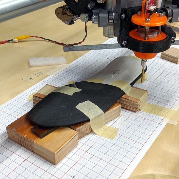
In principle, the grid keeps the object aligned with the machine axes and the blocks put the upper surface more-or-less parallel with the platform. The XY origin, at the G28 location I’ve been using for tool changes, is on the midline of the sole, with Z touched off by probing the platform beside the sole.
The only interesting part of the orthotic is the rigid white plastic plate, which extends about 20 mm into a pocket in the black foam, so the probe area excludes the bendy part.
I’m abusing the bCNC Auto-level probe routine to get the height map, because it produces a tidy file of XYZ coordinates with three header lines describing the overall probe area:
-50 140 39
-50 50 21
-2 35 500

-50 -50 0.11
-45 -50 0.06
-40 -50 0.005
The first two lines give the X and Y coordinate ranges and number of samples. The third line is the Z axis range and probe speed (?). After that, it’s just probed XYZ coordinates, all the way down.
Meshlab can import ASC files consisting of XYZ coordinates, with the ability to skip a specific number of header lines:

If you don’t skip those three lines, then you get three additional points, far off in XYZ space, that will confuse the next step.
Checking the Grid Triangulation box (the default) produces a nicely lofted sheet:
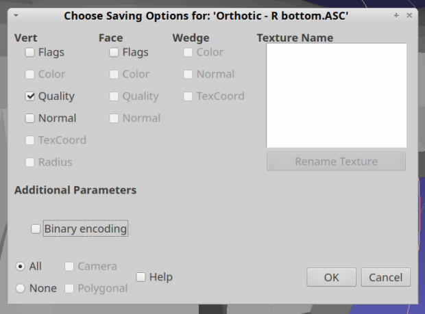
It is, however, a single-sided sheet, not a manifold 3D object. After a few days of screwing around, I’m unable to find any (automatic, reliable, non-manual) way to solidify the thing in Meshlab, so just save it as a PLY file in ASCII format:
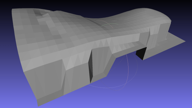
Import it into Meshmixer, Ctrl-A to select the whole thing, click (Select →) Edit → Extrude, pick Y-Axis and Flat EndType, then extrude a convenient base in the negative direction:

For whatever reason, some 3D programs show machine-tool coordinates with Z pointing upward and others aim the Z axis at your face. Both must have made sense at the time, because Meshmixer defaults to swapping the Y and Z coordinates on import / export.
The Density slider controls the number of generated faces in the extruded section, so tune for best results.
I have no idea what Harden does.
Accept the result and you have a solid object suitable for further modeling.

Comments
2 responses to “MPCNC: Z-Axis Probed Height Map to Solid Model”
At the risk of teaching my grandmother to suck eggs, both did make sense at the time: half the software is descended via “3d modeling” from computer graphics / drawing where x and y are obviously the x and y of your monitor, leaving z as the view direction; the other half are descended via CAM from the ideal of a virtual machine tool, where x and y are obviously the bed and z is the tool direction, most canonically in the bridgeport vertical mill style.
Then there’s a top left XY origin with Y increasing down the screen, so you’re looking toward +Z from -Z for a right-handed coordinate system.
I should just not use programs with different assumptions … [heavy sigh]