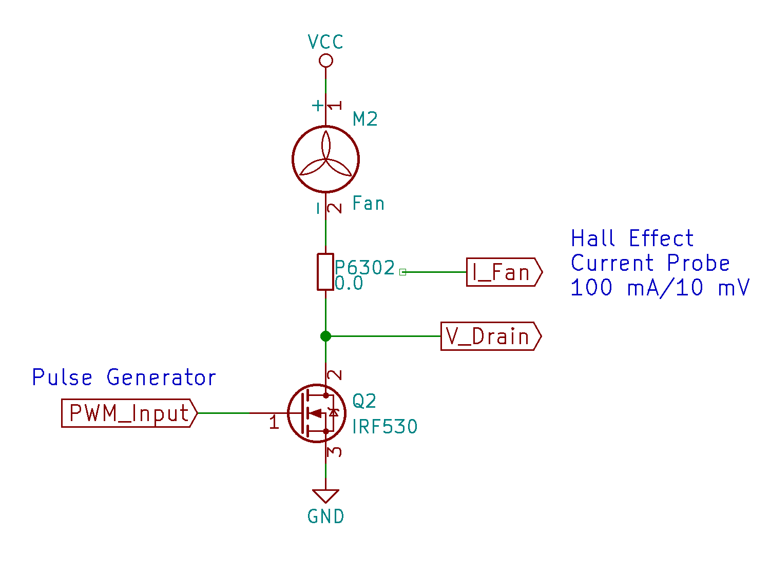
A simpleminded MOSFET circuit provides PWM drive for the BLDC blower:
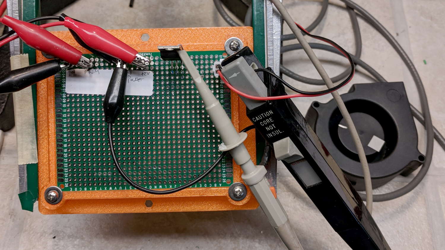
The Tek P6302 current probe looms much larger in real life than in the schematic:
A quick dataset shows the RPM variation against PWM duty cycle:
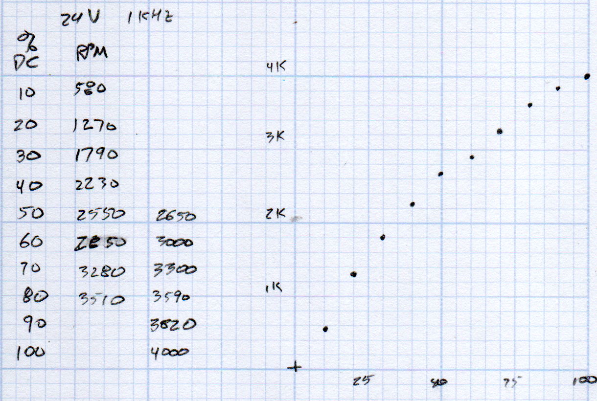
Unsurprisingly, the RPM curve resembles the earlier results against a variable DC supply voltage:

Capturing the current waveform is stalled behind another project, but it has exactly the voltage spikes you’d expect from forcibly switching an inductive load.

Comments
One response to “BLDC Fan RPM vs. PWM Duty Cycle”
[…] 50% PWM at 1 kHz into the simpleminded 24 V BLDC driver produces the results you’d […]