Spoiler alert: having spent a while trying to fit the DDS calculations into fixed-point numbers stuffed into a single 32 bit unsigned long value, it’s just a whole bunch of nope.
The basic problem, as alluded to earlier, comes from calculations on numbers near 32768.0 and 60000.0 Hz, which require at least 6 significant digits. Indeed, 0.1 Hz at 60 kHz works out to 1.7 ppm, so anything around 0.05 Hz requires seven digits.
The motivation for fixed-point arithmetic, as alluded to earlier, comes from the amount of program memory and RAM blotted up by the BigNumber arbitrary precision arithmetic library, which seems like a much bigger hammer than necessary for this problem.
So, we begin.
Because the basic tuning increment works out to 0.0291 Hz, you can’t adjust the output frequency in nice, clean 0.01 Hz clicks. That doesn’t matter, as long as you know the actual frequency with some accuracy.
Setting up the DDS requires calculations involving numbers near 125.000000 MHz and 2³², both of which sport nine or ten significant figures, depending on how fussy you are about calibrating the actual oscillator frequency and how you go about doing it. Based on a sample of one AD8950 DDS board, the 125 MHz oscillator runs 300 to 400 Hz below its nominal 125 MHz: about 3 ppm low, with a -2.3 Hz/°C tempco responding to a breath. It’s obviously not stable enough for precise calibration, but even 1 ppm = 125 Hz chunks seem awkwardly large.
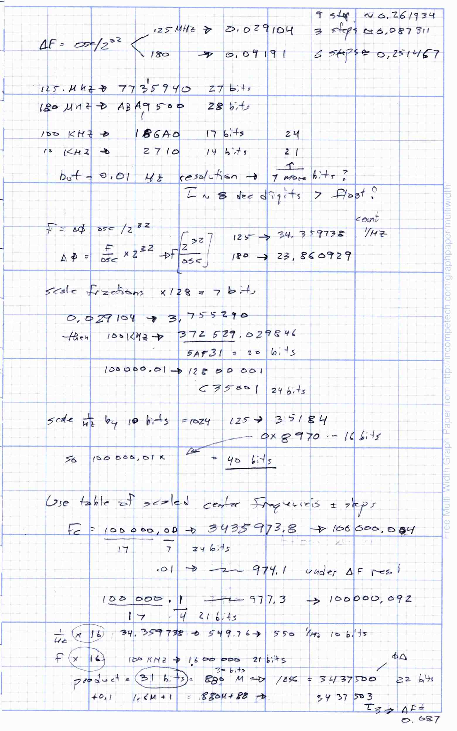
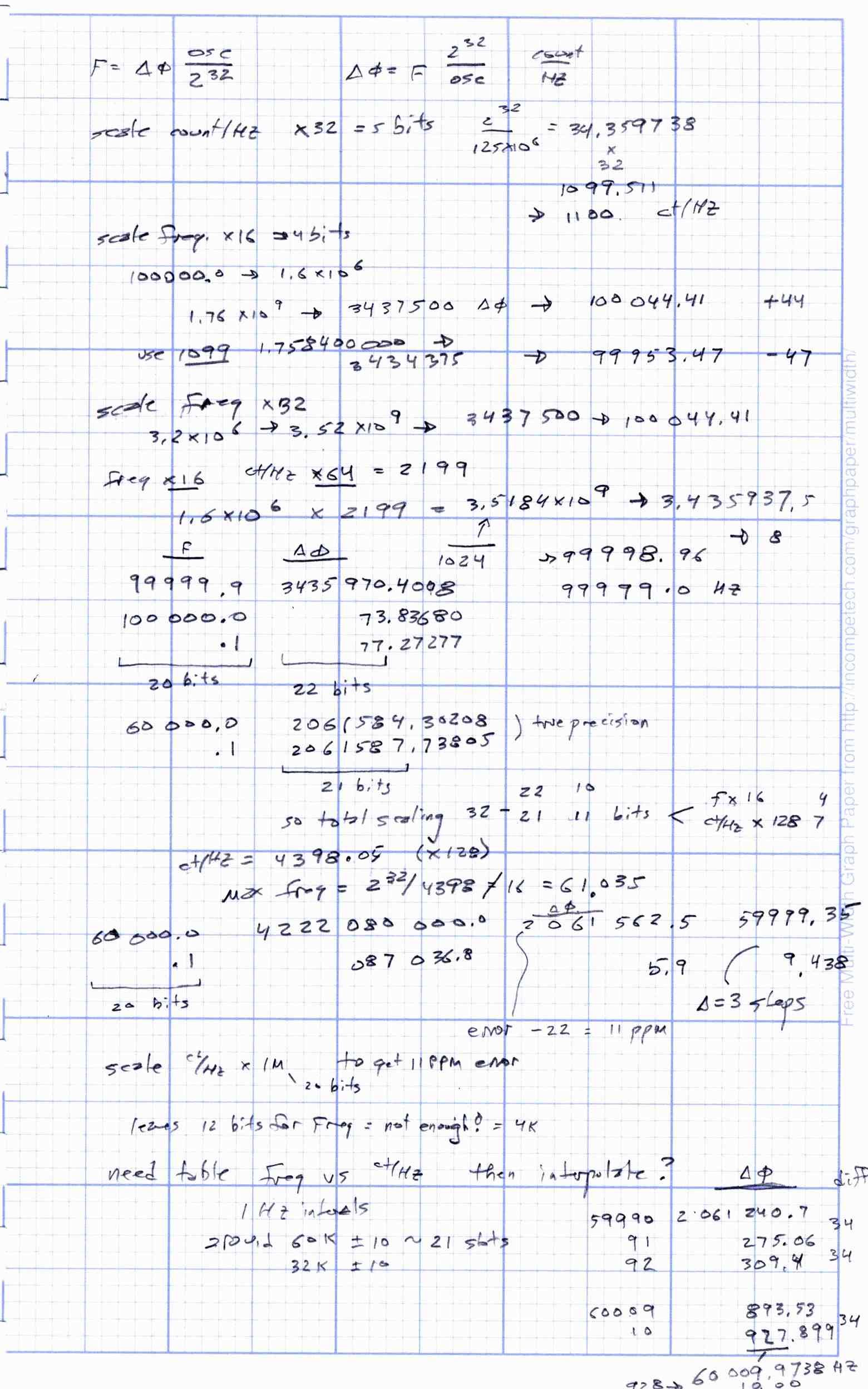
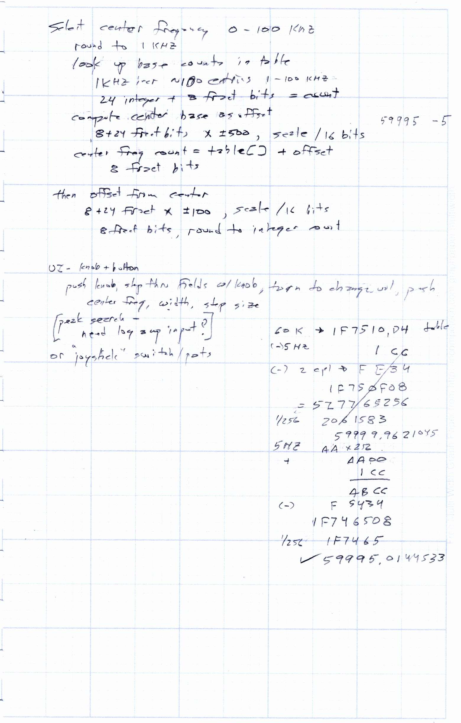
Many of the doodles below explore various ways to fit integer values up to 125 MHz and fractions down to 0.0291 Hz/count into fixed point numbers with 24 integer bits + 8 fraction bits, perhaps squeezed a few bits either way. Fairly obviously, at least in retrospect, it can’t possibly work: 125×10⁶ requires 28 bits. Worse, 8 fraction bits yield steps of 0.0039, so you start with crappy resolution.
The DDS tuning word is about 2×10⁶ for outputs around 60 kHz, barely covered by 21 bits. You really need at least seven significant figures = 0.1 ppm for those computations, which means the 125 MHz / 2³² ratio must carry seven significant figures, which means eight decimal places: 0.02910383 and not a digit less.
En passant, it’s disturbing how many Arduino DDS libraries declare all their variables as double and move on as if the quantities were thereby encoded in 64 bit floating point numbers. Were that the case, I’d agree 125e6 / pow(2.0,32) actually meant something, but it ain’t so.
The original non-linear doodles, which, despite containing some values useful in later computations, probably aren’t worth your scrutiny:


Comments
12 responses to “DDS Musings: Arithmetic with 32-bit Fixed Point Numbers”
Um, I must be missing something here (as is usually the case!). But…what about replacing the 125MHz oscillator with your own 455kHz ceramic resonator clock? Doesn’t this give you ‘adequate’ resolution with the 32-bit word for the 60kHz output and adequate protection from unwanted alias products?
OK, now everyone that’s laughing at me can explain using small words why this ain’t the way to go.
Nope, you’re spot on: a good choice of frequency can make up for nearly everything else.
Turns out the AD9850 requires an actual clock input, either a full logic-level square wave or a sinusoid centered on VCC/2, so a simple crystal or ceramic resonator won’t do. I should swap in a 4.096 MHz clock-in-a-can for 1 mHz frequency resolution, although the only ones I’ve seen run at 3.3 V and would require level shifters for the control lines.
The justification for all this software flailing around is working with what’s cheap & readily available for an upcoming Circuit Cellar column. That might not be enough justification … [grin]
No, the word “clock” in that sentence should have suggested I meant an external circuit of some sort. My suggestion would be the Jim Williams one transistor diode-temp-compensated oscillator (in his oscillator app note) which works like gang-busters, and gives a tidy TTL input into the AD9850. 4.096MHz is not a great choice compared with 455kHz IMHO. The resolution around 60kHz (if that really matters) is 10 times worse than the readily available 455kHz version (Got an old TV remote handy) and that frequency doesn’t give integer advantages in the math. Plus, the current consumption of the AD9850, awful at the best of times, drops still further. Heck, what’s not to like?
Gotcha! I saw “resonator” and jumped to the wrong conclusion.
I think you need a much higher DDS clock to push the images farther away from the 60 kHz (-ish) output. With a 455 kHz clock, the 395 kHz image would be less than three octaves up, the 515 kHz image barely over three, and the reconstruction filter would get fugly.
FWIW, I just saw some 4.096 MHz oscillators in a surplus listing and barely fought myself to a standstill. [sigh]
Perhaps it’s time to try an ARM-based board. The Teensy 3.2 is well-respected, works in the Arduino environment, and it implements the standard IEEE 754 “double” (though it does so through software; like the Arduino it does not have an FPU, but it does have a hardware multiplier and barrel shifter as well as a much faster instruction clock, all of which make for faster FP emulation). It’s around $20 qty1 shipping from the USA.
(The teensy 3.6 with its M4F-family CPU has an FPU that implements “float” but not “double” as I understand it, so it won’t offer a performance advantage for “double”s)
Alternately, avr-libc documentation implies that int64_t / uint64_t support is available, perhaps you want to re-try your doodles with 64-bit values. (but the internet suggests these are not terribly efficient on code size or runtime)
Aye, I keep thinking I should stock up on a few of those for more complex projects; the $20-ish sticker price is the only real disadvantage compared to the disposable Arduino knockoffs.
In this case, though, I really needed only a couple of extended-precision multiplications and, seeing as how I hadn’t thought through fixed-point notation in a while, it all seemed like an interesting topic. I have the DDS running from 64-bit = uint64_t fixed point numbers, without soaking up a ton of Flash or RAM; it’s less awful that it sounds.
The next few posts will document the whole mess, which should have the same abstract fascination as driving past a really nasty automobile collision …
Well, there are 32 bit arduino knockoffs, ultra cheap STM32F103 “blue pill” boards at ~$2 can run STM32duino, https://github.com/rogerclarkmelbourne/Arduino_STM32 They are most likely fake ST chips (GD32) but seems to work pretty good.
You can also buy real ST chips for cheap ($9-13 dev boards that include a SWD debugger) but the software tools provided by ST are pretty rough so i’d probably recommend against.
Proof of concept tuning with 64-bit integers: https://gist.github.com/jepler/b6eb51bf8cca7ddb1c86e800370d5a4e
Includes a version which takes f_osc and f_tune as integer Hz values, and a version which takes an additional f_tune_millihz value so it can e.g., tune 60000.123Hz if you want. It’s of dubious utility given the assumed accuracy of the oscillator, but perhaps if you’re creating frequency sweeps you’d want it.
In a half billion or so arbitrary test cases, the greatest mistuning compared to the double-precision FP version is 1 tuning count.
Only tested on desktop, not in Arduino/AVR, so caveat emptor.
The program works on an old duemilanove I have sitting around, and the integer-algorithm gives the same reasults as on a desktop OS. Instead of finding problems due to rounding in integer division, though, it finds problems due to the ‘float’ precision, for all the reasons already noted in this blog.
I’m using a commandline gcc workflow, so the sizes of things probably differ from what you get in the Arduino environment. My minimal program weighs in at 342 bytes of code, the integer Hz version is 886 bytes code, and the integer milliHz version is 1028 bytes code; so the cost is 544 bytes and 686 bytes respectively.
The time per conversion is ~75us for the hertz version and ~165us for the milliHz version, doing the specific conversion with f_osc=125000025, f_tune_hz=59999, f_tune_millihz=123. The time spent in the routine probably depends somewhat on the arguments.
Zowie! Nothing like a new problem to take your mind off all your other problems, eh?
I fiddled the serial output, then fired it through the Arduino IDE into a knockoff UNO:
Sketch uses 7738 bytes (23%) of program storage space. Maximum is 32256 bytes.Global variables use 212 bytes (10%) of dynamic memory, leaving 1836 bytes for local variables. Maximum is 2048 bytes.
It trundled along and finished the -250 Hz calculations by bedtime:
-250 31096801.993 1068480118 1068480000 118I must twiddle a pin in my code to measure how long those ops take, too.
[…] Although it’s not advertised, the Arduino / AVR compiler mostly does the right thing with long long = uint64_t variables: add & subtract work fine, but multiplication & division discard anything that doesn’t fit into 64 bits. Fitting a 32 bit integer and a 32 bit fraction into such a thing should eliminate (most) problems with significant figures. […]
[…] eight bytes to every fixed point number may be excessive, but having nine significant figures apiece for the integer and fraction parts […]