Ed Nisley's Blog: Shop notes, electronics, firmware, machinery, 3D printing, laser cuttery, and curiosities. Contents: 100% human thinking, 0% AI slop.
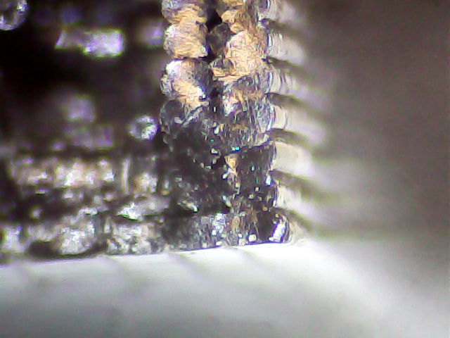
Our Larval Engineer returned the remaining chunk of the failed PLA hood rod pivot from “her” Sienna minivan:
Sienna hood rod pivot – PLA fracture
A closer look at the top surface (facing you in the picture above) shows the threads didn’t fuse into a solid mass across the entire object:
Sienna Hood Pivot – PLA fracture – top
The darker region in the middle comes from the infill pattern, which should have air gaps.
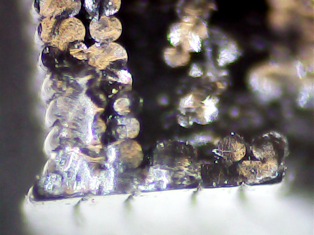
The bottom surface (on the platform during printing) shows how the threads spread out when the nozzle is closer to the platform than the layer thickness:
Sienna Hood Pivot – PLA fracture – bottom right
That’s more pronounced on the other side of the pivot:
Sienna Hood Pivot – PLA fracture – bottom left 1
The infill looks like a separate wall inside the two perimeter threads. That’s pretty much what you get in the space between two close-set walls: there’s not enough room for the full infill pattern.
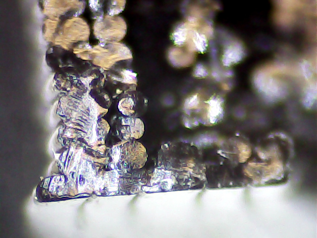
A slightly different focus plane shows the mashed bottom layer, infill sitting atop the bottom layer, and fused perimeter threads:
Sienna Hood Pivot – PLA fracture – bottom left 2
Because 3D printing doesn’t (and really can’t) produce a solid block of plastic, the object will fail much more readily than an injection-molded part. The threads in the most highly stressed section fail first, after which the remainder will just rip apart. In this case, the hood rod provides a huge lever that easily overstresses the plastic; I’m surprised the original part lasted as long as it did.
We all knew PLA wasn’t the right material for the job, right from the start, so we’ll see how the enlarged PETG version works in the field.
Starting with a blank 120 GB SSD, I had to disable the “Plug-n-Play OS” BIOS option to get the Lenovo Q150 to boot from a System Rescue CD USB stick. While the hood was up, I told the BIOS to ignore keyboard errors so it can boot headless.
Partitioning:
50 GB ext4 partition for Mint
8 GB swap
The remainder unallocated
Booting & installing Mint Linux 17.2 XFCE from another USB stick went smoothly, after which it inhaled the usual gazillion updates. Rather than wait for the auto-updater to wake up and smell the repositories, I generally get it done thusly:
Add my user to the dialout group, so I have access to the USB serial converter on /dev/ttyUSB0 that will drive the plotter.
Configure a static IP address that appears in the appropriate /etc/hosts files.
Install some useful packages:
nfs-common
openssh-server
htop and iotop
Set up ssh for public key authentication, rather than passwords, on an unusual port, so everything else can happen from the Comfy Chair upstairs.
Install packages that Chiplotle will need:
build-essential
python-setuptools
python-dev
python-numpy
python-serial
hp2xx
I think some of those would be auto-installed as dependencies by the next step, but now I can remember what they are for the next time around this action loop:
sudo easy_install -U chiplotle
... blank line to show underscore above ...
Plug the old hard drive into a USB-SATA adapter to copy:
A pre-Christmas sale brought a cheap SSD that rendered my oath not to install one in the Lenovo Q150 inoperative, so I had to figure out how to open the case. Removing the visible screws didn’t release the cover, but some exploratory prying eventually popped the internal snap latches. Knowing the latch & screw locations will simplify harvesting the SSD when that time comes…
Front (with USB & SPDIF jacks):
Lenovo Q150 – case latches – front
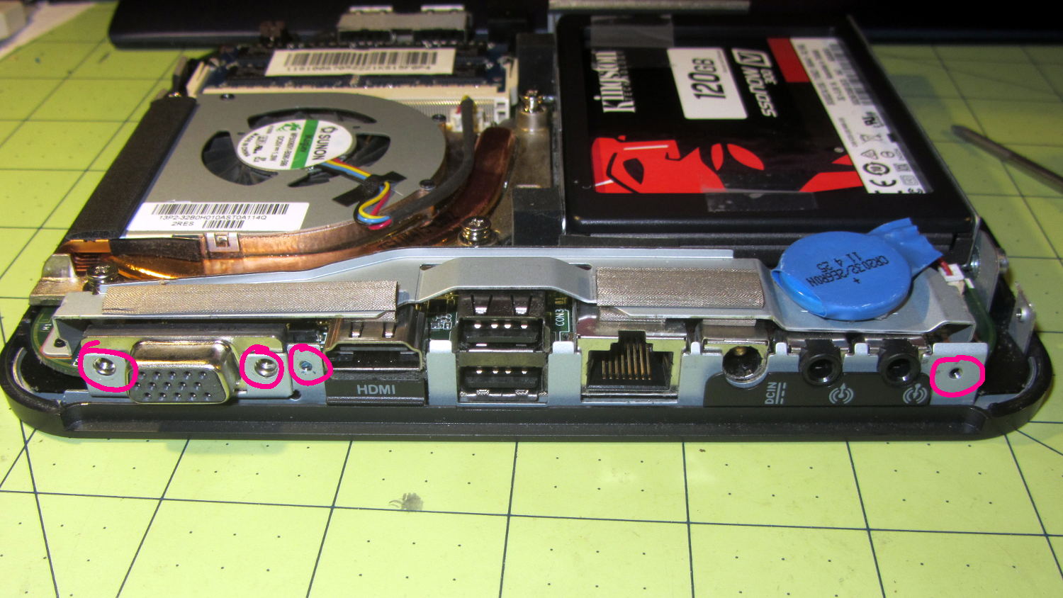
Rear (with all the other jacks):
Lenovo Q150 – case screws – rear
Top (with the heatsink outlet):
Lenovo Q150 – case latches – top
Bottom (with the mounting boss):
Lenovo Q150 – case latch screws – bottom
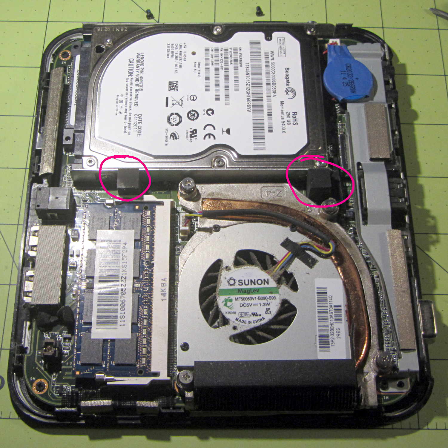
With the cover off, the inside looks like this:
Lenovo Q150 – interior overview
The two rubber blocks glued to the hard drive bracket (carrier / sled / whatever) conceal the screws holding that side to the chassis. However, removing the blocks and the screws didn’t release the bracket, because it had what looked like a black adhesive layer below the screw flanges:
Lenovo Q150 – hidden drive bracket screw
Gentle prying from the edge of the bracket eventually released it, showing that the black plastic was just an insulating layer. Below that, two thin foam strips had firmly affixed themselves to the PCB, despite not having any adhesive on that side:
Lenovo Q150 – drive bracket – foam strips
With the bracket on the bench, installing the SSD went exactly as you’d expect and reinstalling the cover was, quite literally, a snap.
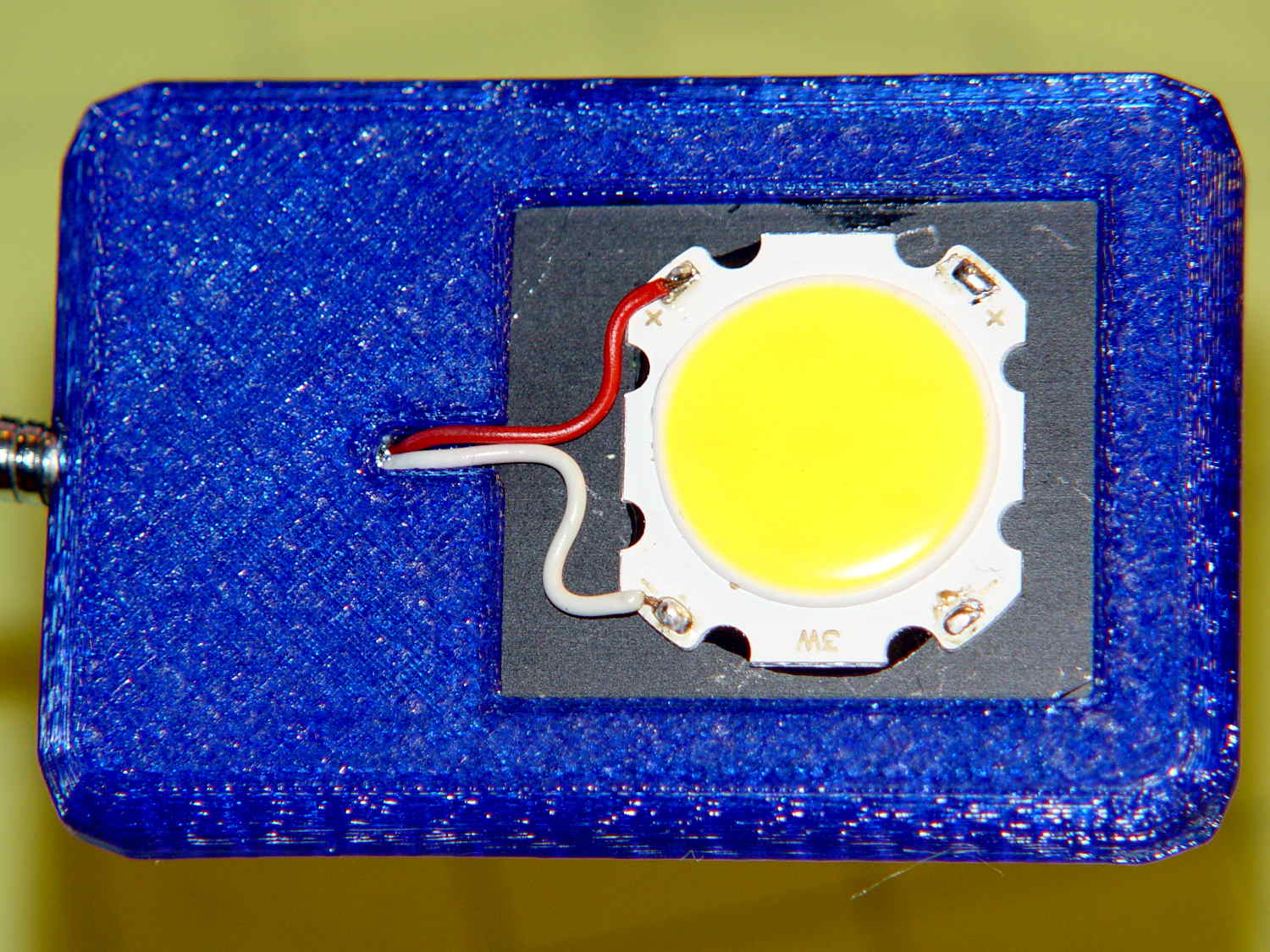
The LED’s aluminum baseplate (perhaps there’s an actual “board” inside the yellow silicone fill) is firmly epoxied to a small heatsink from the Big Box o’ Heatsinks, chosen on the basis of being the right size and not being too battered.
The rather limited specs say the LED supply voltage can range from 9 to 12 V, suggesting a bit of slack, with a maximum dissipation of 3 W, which definitely requires a heatsink.
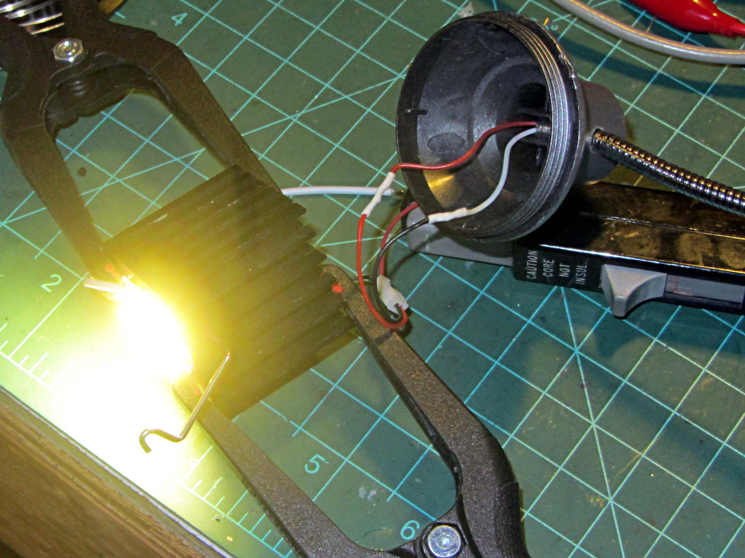
The First Light test looked promising:
COB LED Desk Lamp – first light
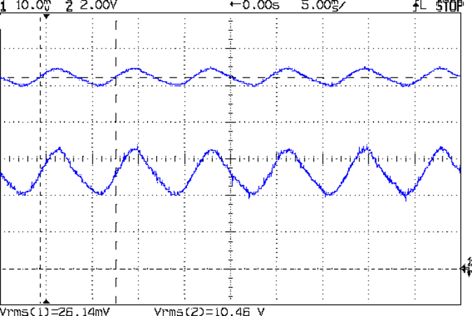
That’s driven from the same 12 VDC 200 mA wall wart that I used for the failed ring light version. Measuring the results shows that the supply now runs at the ragged edge of its current rating, with the output voltage around 10.5 V with plenty of ripple:
COB LED V I 100ma div
The 260 mA current (bottom, trace 1 at 100 mA/div) varies from 200 to 300 mA as the voltage (top, trace 2 at 2 V/div) varies between 10 V and a bit under 11 V. If you believe the RMS values, it’s dissipating 2.7 W and the heatsink runs at a pleasant 105 °F in an ordinary room. The wall wart gets about as warm as you’d expect; it contains an old heavy-iron transformer and rectifier, not a trendy switcher.
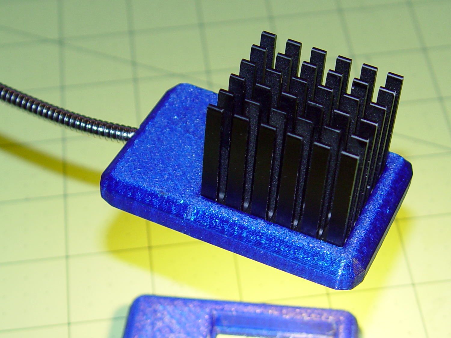
The heatsink mount looks nice, in a geeky way:
COB LED Desk Lamp – side detail
The left side must be that long to anchor the gooseneck; I thought about tapering the slab a bit, but, really, it’s OK the way it is. Dabs of epoxy hold the gooseneck and heatsink in place.
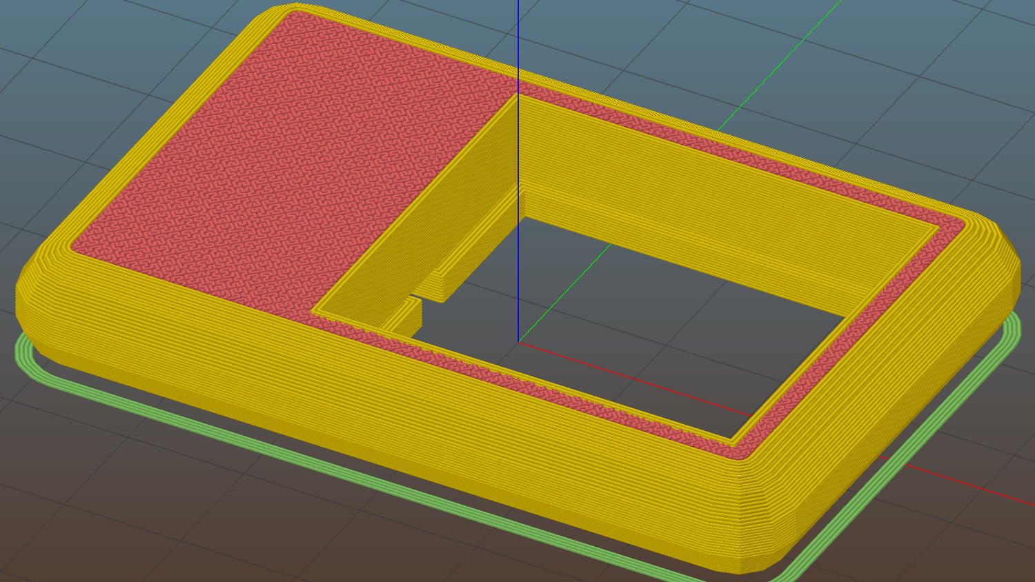
The heatsink rests on a small ledge at the bottom of the slab that’s as tall as the COB LED is thick, with a wire channel from the gooseneck socket:
COB LED Heatsink mount – Slic3r
The Hilbert Curve infill on the top produces a textured finish; I’m a sucker for that pattern.
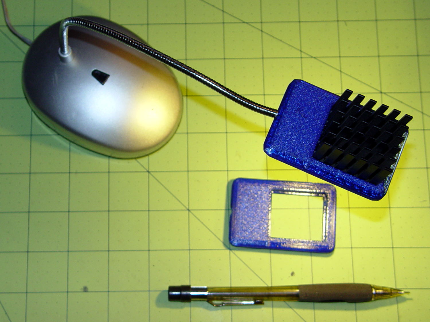
The old lamp base isn’t particularly stylin’, but the new head lights up my desk below the big monitors without any glare:
This file contains hidden or bidirectional Unicode text that may be interpreted or compiled differently than what appears below. To review, open the file in an editor that reveals hidden Unicode characters.
Learn more about bidirectional Unicode characters
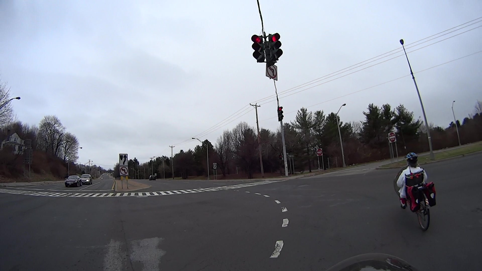
We ride through the intersection at the Rt 55 end of Burnett Blvd a lot, because it’s the only route between Raymond Avenue and the Dutchess Rail Trail. Previous posts have documented the signal timing, but this sequence shows the situation we’ve feared from the beginning… cross traffic not stopping because we are in the intersection with an opposing green light.
The sequence numbers indicate the frame at 60 f/s.
T +0.000 = our signal just turned green:
Burnett at Rt 55 2015-12-14 – 0096 – Green
T +1.250 s = the drivers ahead of us release their brakes and begin rolling:
Burnett at Rt 55 2015-12-14 – 0171 – Green start
T +2.400 s = we begin rolling:
Burnett at Rt 55 2015-12-14 – 0240 – Green rolling
It’s worth noting that we cannot start any earlier, unless you regard jumping the green and passing cars at an intersection as Good Practices, which we don’t.
T +7.217 s = the yellow signal goes on in our direction:
Burnett at Rt 55 2015-12-14 – 0529 – Yellow
That’s six whole seconds from the time the cars started rolling and 4.8 s from the time we started.
Notice the white car to our right that’s stopped in the leftmost eastbound lane of Rt 55.
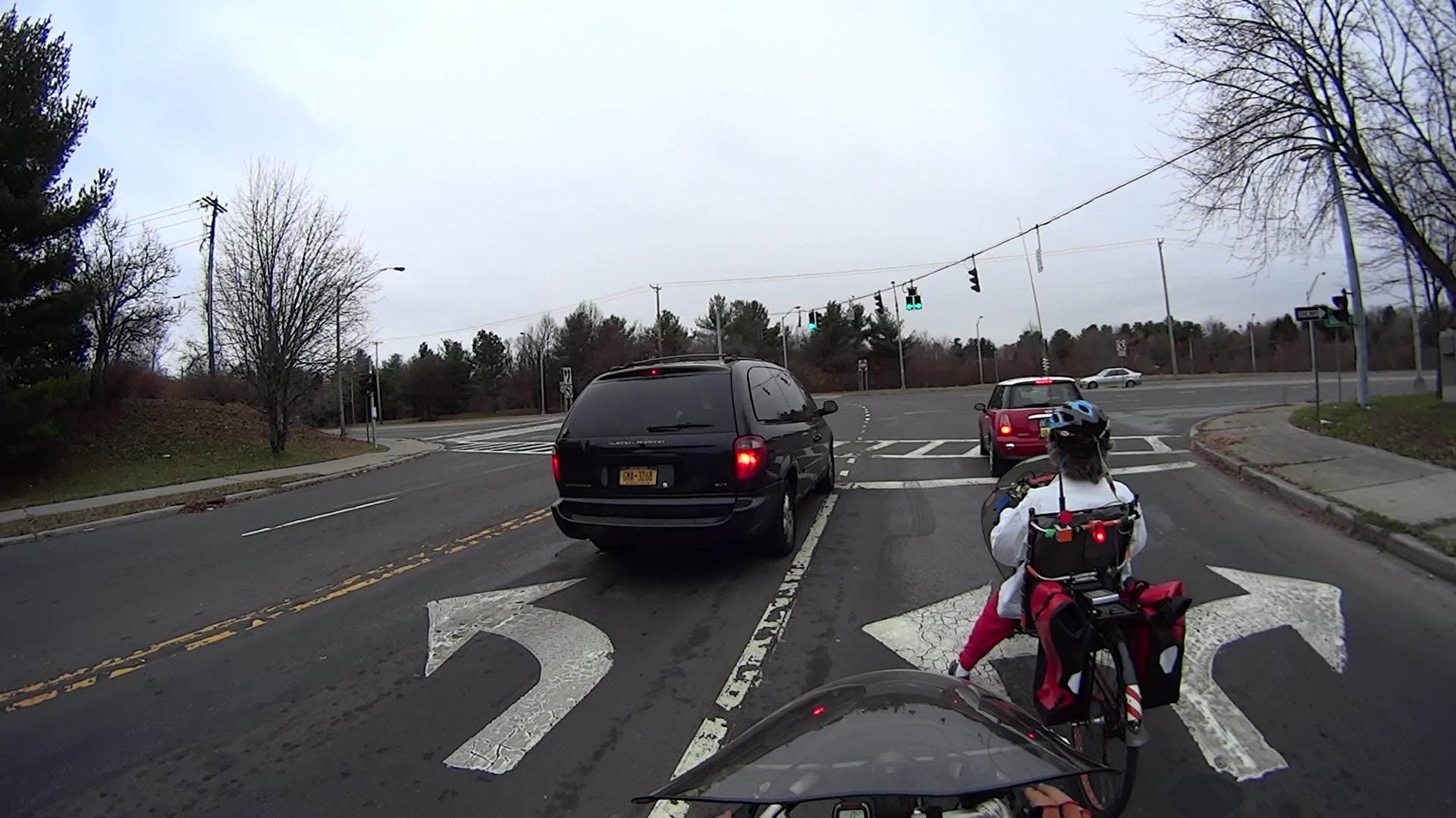
T +12.100 s = our signal turns red:
Burnett at Rt 55 2015-12-14 – 0822 – Red
I’ve reached the middle of the intersection, Mary’s about centered on the three eastbound lanes of Rt 55.
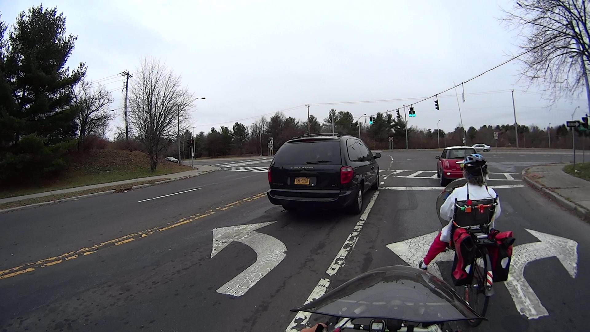
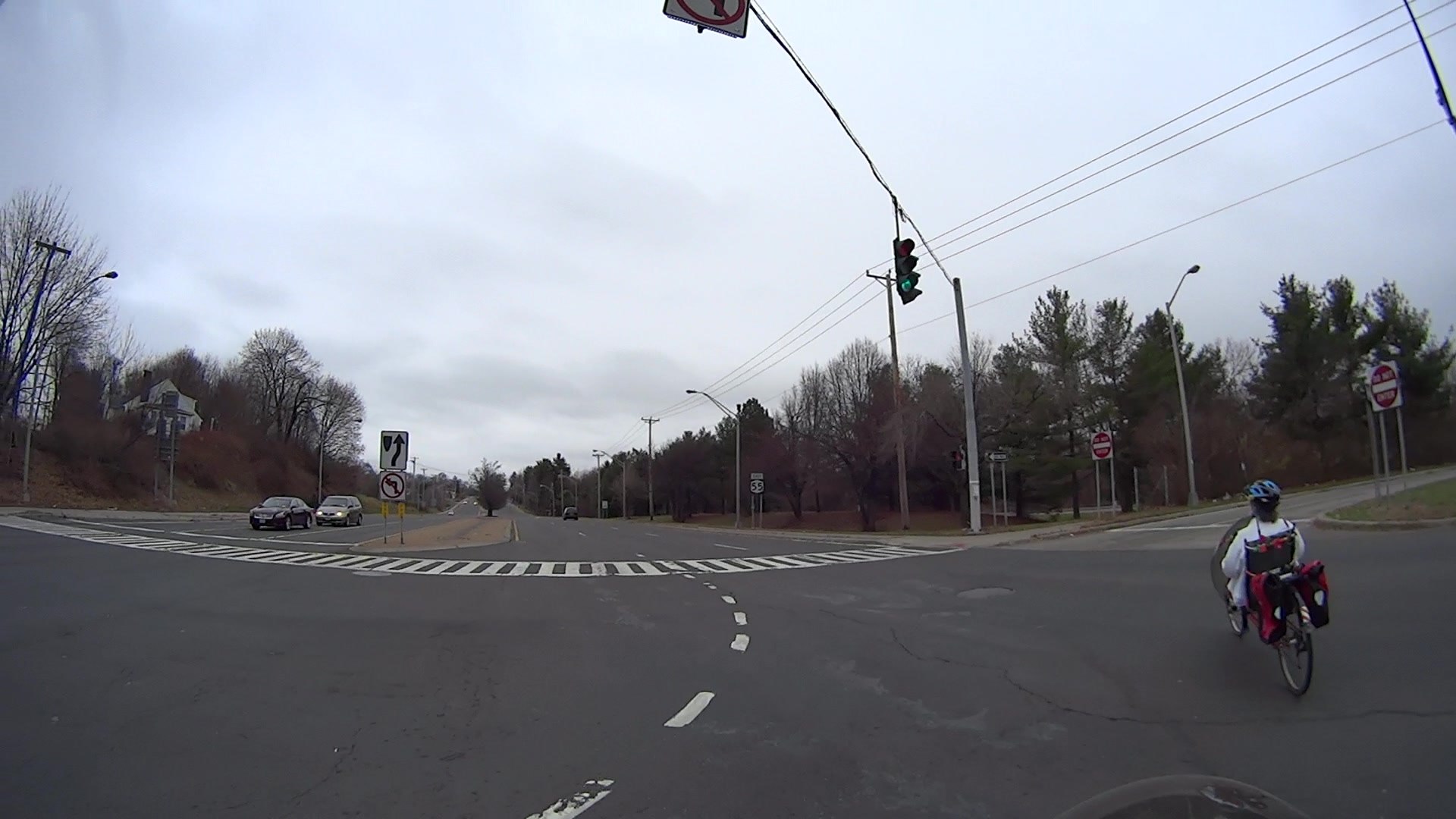
T +13.333 s = the opposing signal turns green:
Burnett at Rt 55 2015-12-14 – 0895 – Opp Green
Traffic in both directions of Rt 55 can now begin moving, but the white car remains stopped; it’s almost directly behind me in the leftmost lane. Because Mary is following the curved line guide lines, she’s just entering the rightmost lane. What you can’t see is a black car approaching from behind her that didn’t have to stop.
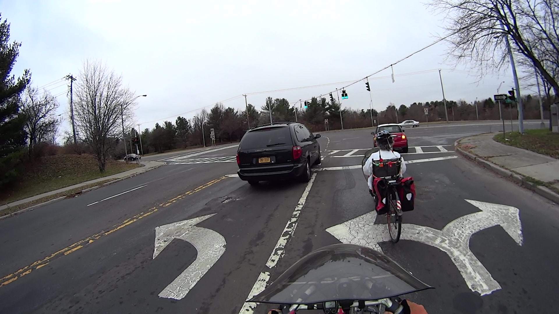
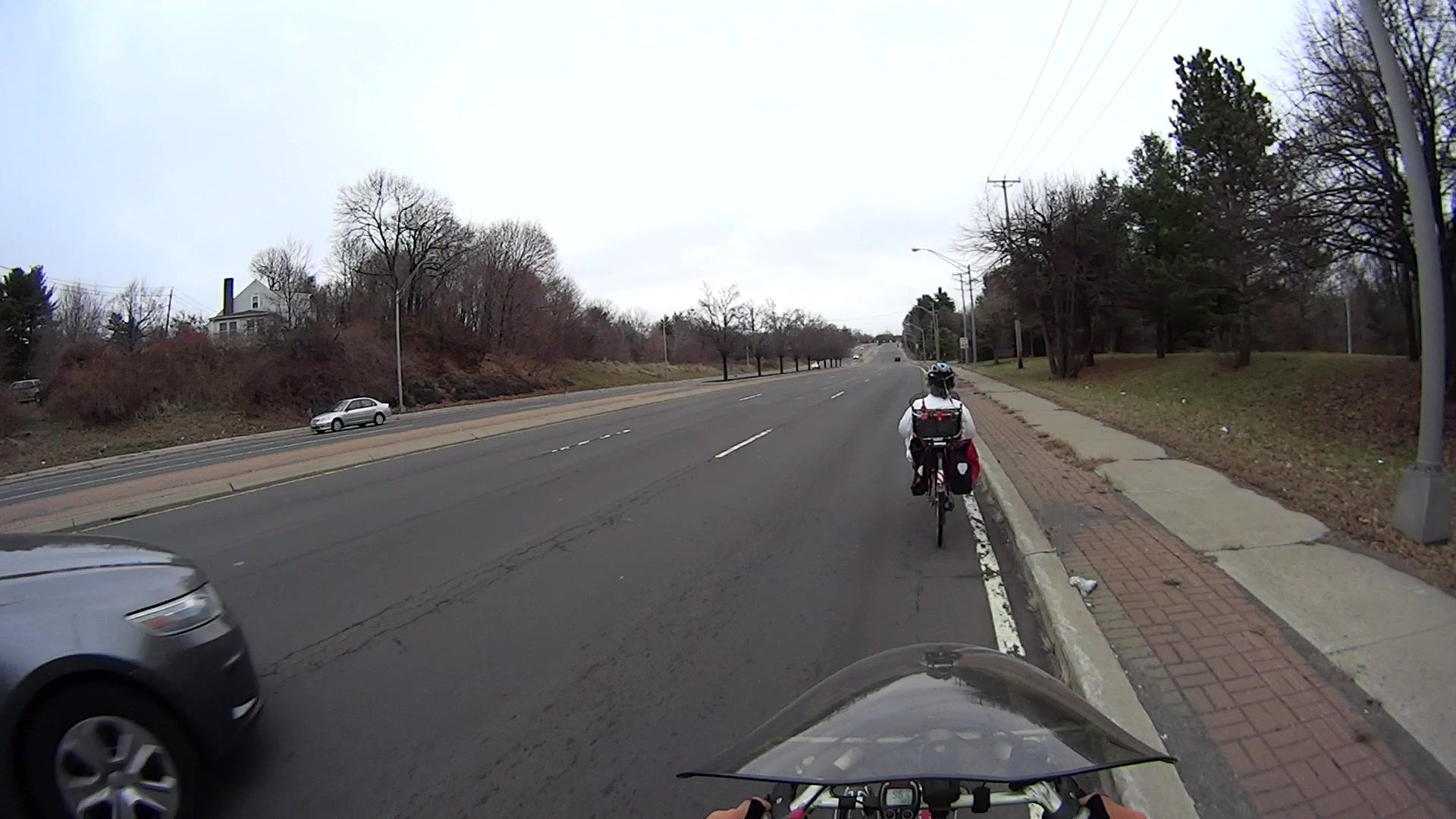
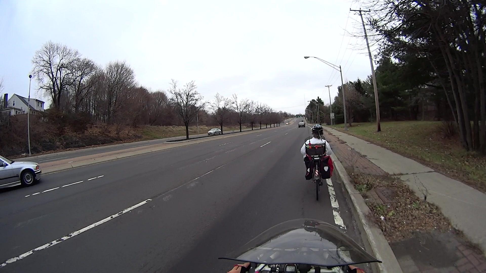
T +20.950 s = the car in the right lane that didn’t have to stop passes me:
At 40 mph = 60 ft/s, that car passed the stop line 2.3 s earlier, at T +18.7 s, when I was still crossing the right lane.
It’s entirely likely that the driver didn’t see either of us while approaching the intersection, because he (let’s assume a he for the sake of discussion) had a green light nearly 5 s = 300 ft before reaching the stop line. Unless he’s paying more attention than most drivers, he was intent on the signal to judge whether he must slow down; for the last 7.3 s he’s known that the intersection is clear, because nobody else should be in the intersection against his green signal.
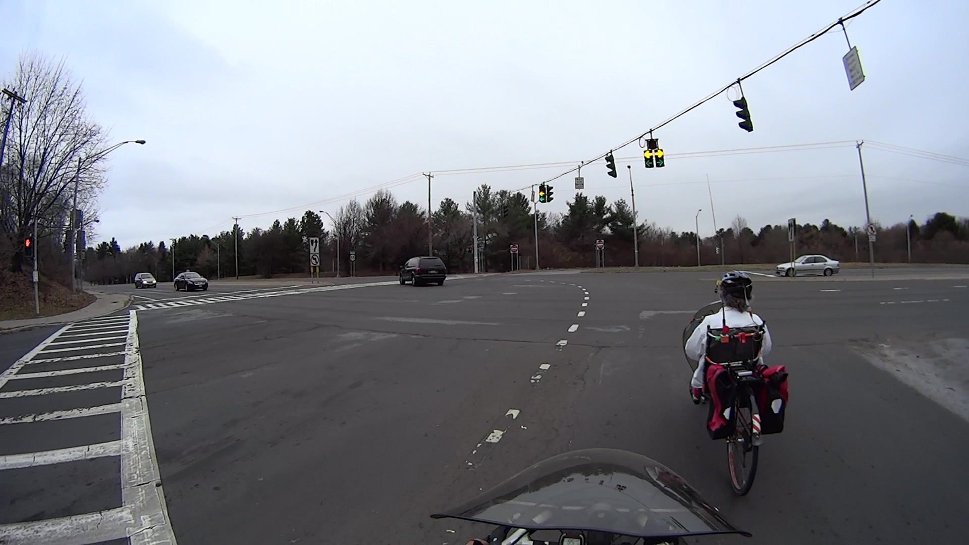
T +24.667 s = The white car in the left lane passes Mary:
Burnett at Rt 55 2015-12-14 – 1576 – Second car
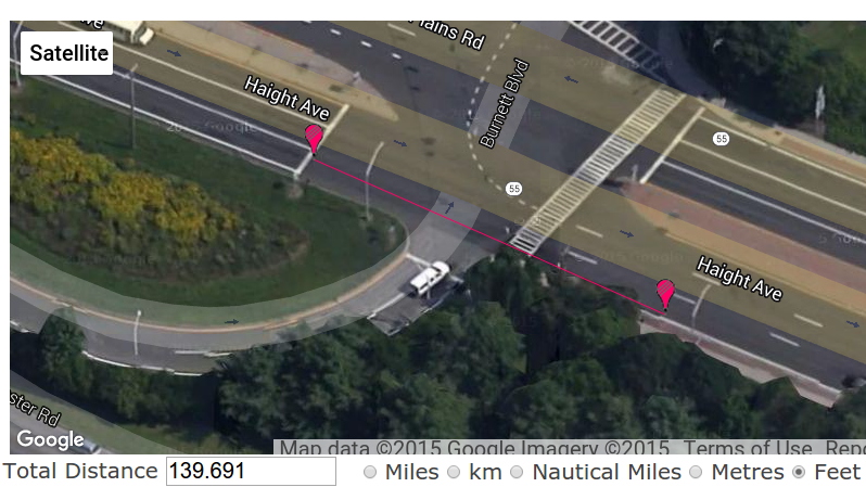
All I’m asking NYSDOT to do is lengthen the signal timing so we’re not caught in the middle of the intersection by opposing traffic with a green signal. Adding a few seconds onto the yellow and minimum cycle time doesn’t seem unreasonable, but it’s been six months since I reported the problem with no action; I’ve pinged their Bicycle & Pedestrian coordinator several times with no response.
If their engineers are “studying” the situation, it’s not producing any visible results; they haven’t asked me for any additional data.
I Am Not A Lawyer, but I think my collection of photos should provide sufficient evidence to convince a jury that NYSDOT is totally liable for any bicycling injuries at that intersection, based on the inability of cyclists to meet the signal timing. I really don’t want to find out if I’m right…