A trio of N2O cartridges / capsules made their way into the Basement Laboratory and cried out to be fitted with fins:

My original model tinkered up a cartridge from solid object primitives, but I’ve since discovered that cheating produces a much better and faster and easier result for cylindrical objects:
The trick is getting an image of the original object from the side, taken from far enough away to flatten the perspective:
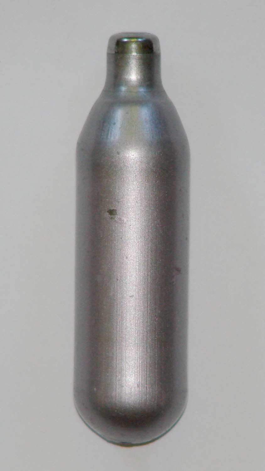
Then overlay and scale a grid to match the actual length:

The grid has 1 mm per minor square, centered along the cartridge’s axis, and zeroed at the tip; I rotated the cartridge image by half a degree to line it up with the grid.
Print it out on actual paper so you can eyeball the measurements and write ’em where you need ’em:

Which becomes an OpenSCAD polygon definition:
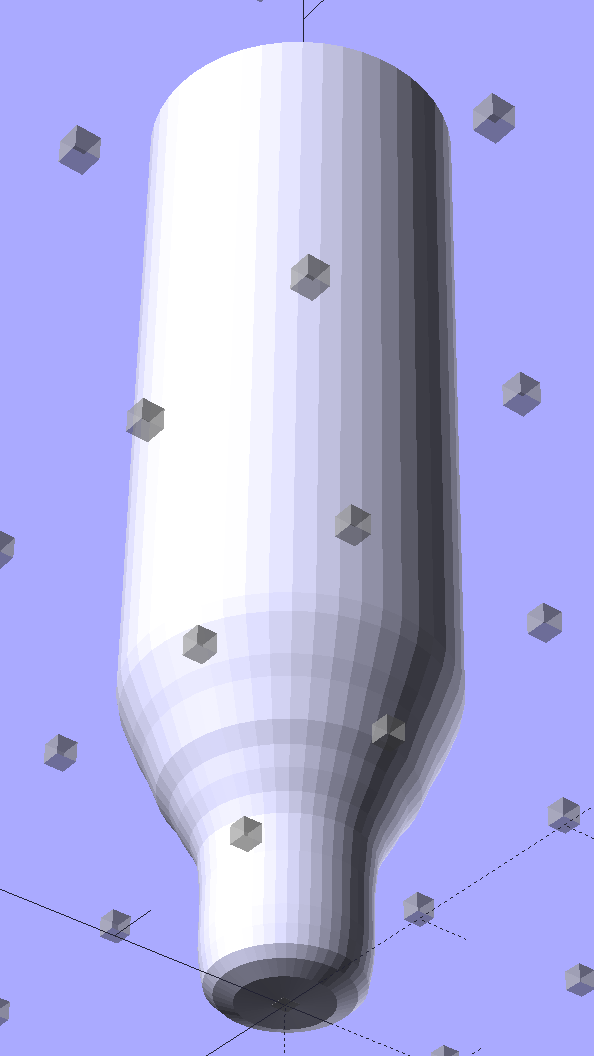
RADIUS = 0;				// subscript for radius values
HEIGHT = 1;				//   ... height above Z=0 at seal flange

//-- N2O 8 g capsule

CartridgeOutline = [			// X values = measured radius, Y as distance from tip
	[0.0,0.0],					//  0 cartridge seal tip
	[2.5,0.1],					//  1 seal disk
	[3.5,0.5],[4.0,1.0],		//  2 tip end
	[4.2,2.0],[4.3,3.0],		//  4 tip
	[4.3,6.0],					//  6 chamfer
	[4.5,8.0],					//  7 taper
	[4.9,9.0],					//  8
	[5.5,10.0],					//  9
	[6.0,11.0],					// 10
	[6.7,12.0],					// 11
	[7.1,13.0],					// 12
	[7.5,14.0],					// 13
	[8.0,15.0],					// 14
	[8.4,16.0],					// 15
	[8.8,17.0],					// 16
	[9.0,18.0],[9.0,58.0],		// 17 body
	[0.0,65.0]					// 19 dummy end cone
	];

TipLength = CartridgeOutline[6][HEIGHT];
TipOD = 2*CartridgeOutline[5][RADIUS];

BodyOD = 2*CartridgeOutline[17][RADIUS];
BodyOAL = CartridgeOutline[19][HEIGHT];
Because the rounded end of the cartridge doesn’t matter, I turned it into a cone.
Twirl that around the Z axis and It Just Works:
module Cartridge() {

 rotate_extrude($fn=CartridgeSides)
 polygon(points=CartridgeOutline);

}
Which then punches a matching dent in the fin structure:

The lead picture doesn’t quite match the Slic3r preview, as I found the single-width diagonal fins weren’t strong enough. Making them two (nominal) threads wide lets Slic3r lay down three thinner threads in the same space:

That’s letting Slic3r automagically determine the infill and perimeter thread width to make the answer come out right. As nearly as I can tell, the slicing algorithms have become smart enough to get the right answer nearly all of the time, so I can-and-should relinquish more control over the details.
The OpenSCAD source code:
// CO2 capsule tail fins
// Ed Nisley KE4ZNU - October 2015

Layout = "Build"; // Show Build FinBlock Cartridge Fit

//-------
//- Extrusion parameters must match reality!
// Print with +0 shells and 3 solid layers

ThreadThick = 0.25;
ThreadWidth = 0.40;

HoleWindage = 0.2;

Protrusion = 0.1; // make holes end cleanly

function IntegerMultiple(Size,Unit) = Unit * ceil(Size / Unit);

//-------
// Capsule dimensions

CartridgeSides = 12*4; // number of sides

RADIUS = 0; // subscript for radius values
HEIGHT = 1; // ... height above Z=0 at seal flange

//-- N2O 8 g capsule

RW = HoleWindage/2; // enlarge radius by just enough

CartridgeOutline = [ // X values = measured radius, Y as distance from tip
 [0.0,0.0], // 0 cartridge seal tip
 [2.5 + RW,0.1], // 1 seal disk
 [3.5 + RW,0.5],[4.0 + RW,1.0], // 2 tip end
 [4.2 + RW,2.0],[4.3 + RW,3.0], // 4 tip
 [4.3 + RW,6.0], // 6 chamfer
 [4.5 + RW,8.0], // 7 taper
 [4.9 + RW,9.0], // 8
 [5.5 + RW,10.0], // 9
 [6.0 + RW,11.0], // 10
 [6.7 + RW,12.0], // 11
 [7.1 + RW,13.0], // 12
 [7.5 + RW,14.0], // 13
 [8.0 + RW,15.0], // 14
 [8.4 + RW,16.0], // 15
 [8.8 + RW,17.0], // 16
 [9.0 + RW,18.0],[9.0 + RW,58.0], // 17 body
 [0.0,65.0] // 19 dummy end cone
 ];

TipLength = CartridgeOutline[6][HEIGHT];
TipOD = 2*CartridgeOutline[5][RADIUS];

CylinderBase = CartridgeOutline[17][HEIGHT];

BodyOD = 2*CartridgeOutline[17][RADIUS];
BodyOAL = CartridgeOutline[19][HEIGHT];

//-------
// Fin dimensions

FinThick = 1.5*ThreadWidth; // outer square
StrutThick = 2.0*ThreadWidth; // diagonal struts

FinSquare = 1.25*BodyOD;
FinTaperLength = sqrt(2)*FinSquare/2 - sqrt(2)*FinThick - ThreadWidth;

FinBaseLength = 0.7 * CylinderBase;
FinTop = 0.9*CylinderBase;

//-------

module PolyCyl(Dia,Height,ForceSides=0) { // based on nophead's polyholes

 Sides = (ForceSides != 0) ? ForceSides : (ceil(Dia) + 2);

 FixDia = Dia / cos(180/Sides);

 cylinder(r=(FixDia + HoleWindage)/2,h=Height,$fn=Sides);
}

module ShowPegGrid(Space = 10.0,Size = 1.0) {

 Range = floor(50 / Space);

 for (x=[-Range:Range])
 for (y=[-Range:Range])
 translate([x*Space,y*Space,Size/2])
 %cube(Size,center=true);

}

//-------
// CO2 cartridge outline

module Cartridge() {

 rotate_extrude($fn=CartridgeSides)
 polygon(points=CartridgeOutline);

}

//-------
// Diagonal fin strut

module FinStrut() {
 intersection() {
 rotate([90,0,45])
 translate([0,0,-StrutThick/2])
 linear_extrude(height=StrutThick)
 polygon(points=[
 [0,0],
 [FinTaperLength,0],
 [FinTaperLength,FinBaseLength],
 [0,(FinBaseLength + FinTaperLength)]
 ]);
 translate([0,0,FinTop/2])
 cube([2*FinSquare,2*FinSquare,FinTop], center=true);
 }
}

//-------
// Fin outline

module FinBlock() {

$fn=12;
 render(convexity = 4)
 union() {
 translate([0,0,FinBaseLength/2])
 difference() {
 intersection() {
 minkowski() {
 cube([FinSquare - 2*ThreadWidth,
 FinSquare - 2*ThreadWidth,
 FinBaseLength],center=true);
 cylinder(r=FinThick,h=Protrusion,$fn=8);
 }
 cube([2*FinSquare,2*FinSquare,FinBaseLength],center=true);
 }
 difference() {
 cube([(FinSquare - 2*FinThick),
 (FinSquare - 2*FinThick),
 (FinBaseLength + 2*Protrusion)],center=true);
 for (Index = [0:3])
 rotate(Index*90)
 translate([(FinSquare/2 - FinThick),(FinSquare/2 - FinThick),0])
 cylinder(r=2*StrutThick,h=(FinBaseLength + 2*Protrusion),center=true,$fn=16);
 }
 }

 for (Index = [0:3])
 rotate(Index*90)
 FinStrut();

 rotate(180/12)
 cylinder(d=IntegerMultiple(TipOD + 6*ThreadWidth,ThreadWidth),h=TipLength);
 }
}

//-------
// Fins

module FinAssembly() {

 difference() {
 FinBlock();
 translate([0,0,2*ThreadThick]) // add two layers to close base cylinder
 Cartridge();
 }

}

module FinFit() {

 translate([0,0.75*BodyBaseLength,2*ThreadThick])
 rotate([90,0,0])
 difference() {
 translate([-FinSquare/2,-2*ThreadThick,0])
 cube([IntegerMultiple(FinSquare,ThreadWidth),
 4*ThreadThick,
 1.5*BodyBaseLength]);
 translate([0,0,5*ThreadWidth])
 Cartridge();
 }


}

//-------
// Build it!

ShowPegGrid();

if (Layout == "FinStrut")
 FinStrut();

if (Layout == "FinBlock")
 FinBlock();

if (Layout == "Cartridge")
 Cartridge();

if (Layout == "Show") {
 FinAssembly();
 color("LightYellow") Cartridge();
}

if (Layout == "Fit")
 FinFit();

if (Layout == "Build")
 FinAssembly();

Comments
3 responses to “Improved Gas Cartridge Fins”
Have you taken to huffing this stuff? ;-O
I usually take the picture, do a perspective correction if needed and then import it into SketchUp (or whatever tool I’m using for the project), scale it in place and trace the outline directly. Works a charm, and no trees need to be harmed by printing it out… well unless it’s a woodworking project :)
I tried using OpenSCAD for non trivial objects, but it turned out much slower then using a point and click CAD package. I even tried that OpenSCAD front-end but it doesn’t really add anything to the party – or more likely, I was using it wrong :)
I salvaged those from the guy doing whipped cream at a Locust Grove Sunset Sensations fundraiser and, for sure, he didn’t have time for huffing!