Ed Nisley's Blog: Shop notes, electronics, firmware, machinery, 3D printing, laser cuttery, and curiosities. Contents: 100% human thinking, 0% AI slop.
The BOB Yak trailer I tote behind the ‘bent has a flag with a two-part pole which generally stays together; I pull the entire affair out of the frame socket when I hang the trailer up after a trip. The ferrule between the two pole sections recently worked loose and I took it to the Basement Workshop for repair.
The assembled nickel-plated brass (?) ferrule came off both pole sections all too easily, which was a Bad Sign: those little punch marks originally clamped the tubes to the pole. You can’t overestimate the Bad Effects of prolonged vibration on bike parts.
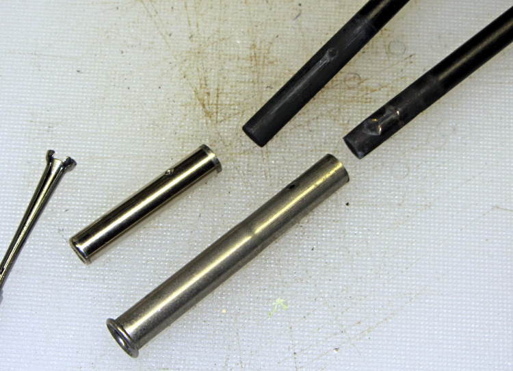
Separating the two ferrule sections required running several pin punches down the bore and tapping gently, all accompanied by considerable muttering; the joint was no longer a slip fit. Eventually I produced this tableau:
BOB Yak trailer flag ferrule
The small hole gauge to the far left showed that the inside of the larger section (on the bottom) had entirely enough clearance for the smaller section, but the rolled ring at its end had somehow shrunk to a tight interference fit.
I’d actually chucked up a piece of rod in the lathe, with the intent of making a mandrel to expand the ring, when I came to my senses. The smaller part was 0.253 inch diameter, so I deployed the letter drills:
an E drill (0.250 inch) just kissed the inside of the ring
an F drill (0.257 inch) opened the ring to a nice sliding fit and still fit easily inside the tube
A few whacks with a center punch reclamped the dimples firmly in place on the dents in the poles.
We don’t often see Turkey Vultures on the ground, so this gathering was unusual:
Turkey vultures on the ground
The depression in the grass suggests something keeled over right there; perhaps they’re rummaging around for leftovers. Although they’re totally graceless on foot, it works well enough for them.
There were two vultures on posts when I stopped, but one joined the ground party before I could deploy the camera. The other bird kept a close eye on me throughout the proceedings:
Turkey vulture on fence post
Look alive!
Pix from the Canon SX230HS, zoomed to its optical limit, and certainly not prizewinners…
OK, somebody decided that the classic metal blade used on all plastic wrap boxes since the dawn of time cost too much, so they decreed that it be replaced with a plastic blade that costs essentially nothing:
Walmart plastic wrap – plastic cutter
Unfortunately, a thin plastic blade also bends easily and, after a few uses, cracks along the midline. After that, it simply doesn’t work; there’s no way to actually tear the plastic off the roll.
It turns out that a common hacksaw blade is exactly the right length and, oriented with the teeth pointing to the left, will rip through plastic wrap like, uh, a hacksaw through plastic:
Walmart plastic wrap – real cutter
That this hack should not be necessary goes without saying…
There’s a layer of double-stick foam tape between the box and blade. It’s probably removable, but I was in a hurry.
I carry the Canon SX230HS in my pocket, so as to have a decent camera ready when it’s needed; yes, it’s in a cloth case. Unfortunately, in recent weeks a tiny hair made its way into the lens stack, where it shows up as a slight blurring just left of center in high f/stop images:
Cheap cartridge heater insulation
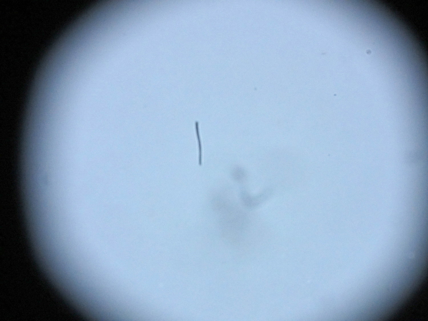
With the camera attached to the stereo zoom microscope, the hair becomes painfully obvious:
Hair on SX230HX Sensor
Of course it’s in the middle of the image. [sigh]
A bit of searching turns up a bootleg technique to remove the front lens from the turret (basically, just twist and pull), but neither of the internal lens surfaces thus revealed lie near a focal plane and, in any event, were surprisingly clean. The hair is probably lodged just in front of the image sensor, most likely stuck to the back of the final lens where it casts a shadow on the sensor. If it wandered around you’d call it a floater.
Dismantling the entire camera and opening the lens stack seems fraught with peril, particularly as the camera pretty much still works fine for normal picture-taking. More pondering is in order…
Part of the Curvelicious Cookie Cutter effort involved making the thinnest possible cutter blade wall consisting of two adjacent threads, because that’s about what the Afinia printer was producing (from a different model). My OpenSCAD code, based on an Inkscape model derived from the as-printed Afinia cutter, enlarges the cookie shape by a specific distance with a Minkowski sum; the model ultimately becomes G-Code directing the extruder nozzle around the outline.
Obviously, that required a bit of fiddling:
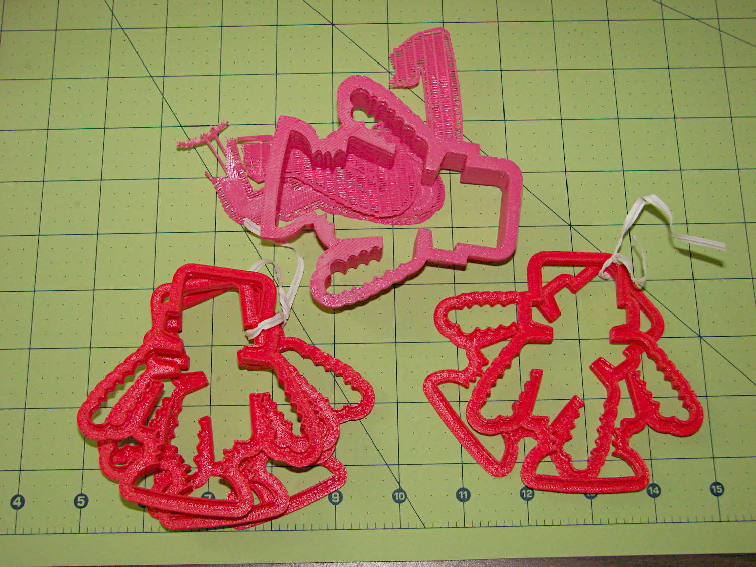
Robot Cutter Variations
The pink cutter on the top came from the Afinia, complete with raft. The red cutters, all with short blades to speed up the printing, came from my M2.
The printer mechanics determine the step/mm values for all four axes: X, Y, Z, and the extruder. The effective diameter of the “gear” driving the filament into the extruder seems subject to some quibbling, but setting it so the thinwall box comes out with the proper filament width seems reasonable. Given those four values, the slicing software can control the extruder speed to produce the proper volume of plastic as the XY speed varies.
The slicing software must also know the raw filament diameter, which seems to be consistent within a few percent for the filaments in my collection. Because a 1% change in filament diameter produces a 3% change in extruded volume, a few percent is about all you can tolerate; broad-tolerance filament may require sensors and adjustments that printers don’t currently offer.
There is one remaining variable, essentially a Fudge Factor, which Slic3r calls the extrusion multiplier. This seems to be a linear factor applied to the extrusion volume, so that increasing the factor proportionally increase the flow rate. Given correct step/mm settings and the measured filament diameter, you (well, I) adjust the extrusion multiplier to get the proper extrusion flow. As it turned out, the multiplier I’ve been using with the M2 worked out to 1.00, although I’ve also used 0.97 on occasion. Although I haven’t read the Slic3r source code to verify this, varying the multiplier by +3% should fudge the diameter by about +0.017 mm = 1% of the measured 1.72 mm.
Note that the Makergear-modified Marlin firmware in the M2 will produce different results, as they use a different value for the extruder gear’s effective diameter. More discussion on that is there.
Soooo, I set up the extrusion multiplier to produce parts with accurate dimensions, because that’s what I care about, and didn’t worry too much about perfect surface finish, because I don’t really care about that. Cookie cutters, however, need a completely filled surface that prevents dough from collecting inside, but have essentially no dimensional accuracy requirements.
The quartet of stumpy cutters bundled together on the left of the top photo explored the effect of changing the extrusion multiplier. I used the same STL model for all the cutters and varied only the extrusion factor, so the results depend only on the plastic flow rate and the M2’s impeccable mechanical stability.
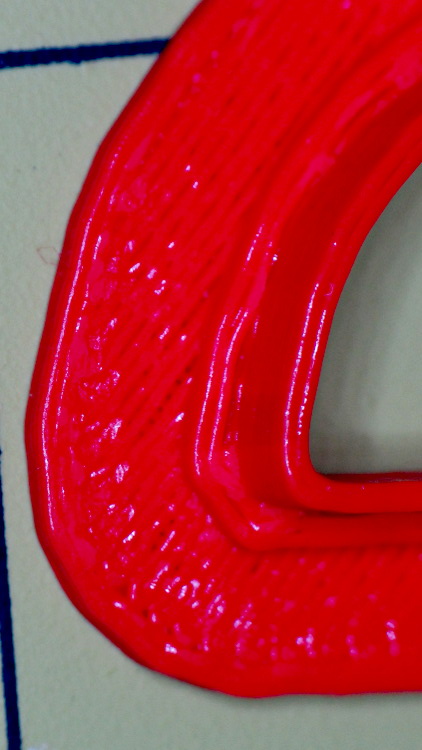
A sharp cusp at 0.96 has a slight opening:
Robot Cutter – 0.96 extrusion multiplier
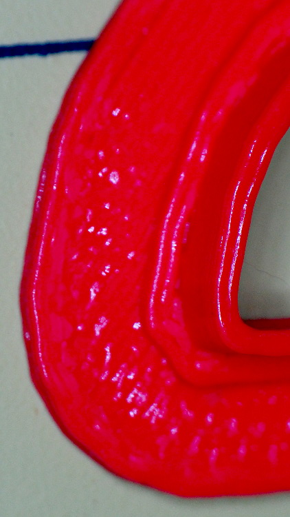
The cusp fills in at 1.10:
Robot Cutter – 1.10 extrusion multiplier
The handle surface is slightly open at 0.96:
Robot Cutter – 0.96 extrusion multiplier
And filled in at 1.10:
Robot Cutter – 1.10 extrusion multiplier
In all those cases, the measured blade thickness varied slightly, but not enough to matter in this application. I didn’t record those numbers and no longer have the models, but … you just tune for best picture.