The Smell of Molten Projects in the Morning

Ed Nisley's Blog: Shop notes, electronics, firmware, machinery, 3D printing, laser cuttery, and curiosities. Contents: 100% human thinking, 0% AI slop.

Tag: Thing-O-Matic

Using and tweaking a Makerbot Thing-O-Matic 3D printer

  • Vermiculture Insect Control

    Fly Escape - overview
    Fly Escape – overview

    A few months after shaking off the previous fruit fly infestation, the worm compost bin has succumbed to another species of fruit fly that’s probably Drosophila melanogaster: much larger, breeds faster, and seems far more tenacious. Even though they’re completely innocuous, Something Must Be Done, but alas there are no insecticides suitable for a worm bin that produces vegetable garden compost. That reduces the situation to the Siege of Stalingrad: cut off their supplies and let them fight it out.

    It seems that fruit flies and their progeny die slightly faster than worms; after three or six weeks without feeding, the flies will should be history and the worms will be eating the dead. Temperatures in the Basement Laboratory Vermiculture Wing will remain in the 60 °F range for the next month or two, so the fly egg-to-adult time will be longer than the usual eight days and this may not work as well as we’d like.

    Assuming that succeeds, however, we’ll be freezing all the kitchen scraps that go into the bin to kill off the fruit fly eggs that arrive here from around the world. There seems no way to get fruits without fruit fly eggs, even with non-organic produce. Organic stuff, well, it’s worse than that.

    I conjured up a Fruit Fly Escape trap that should I hope will lure flies out of the bin to their death, while keeping the worms inside.This won’t help much with the current extreme infestation, but may help dry the bin’s upper layer and, when we get the population knocked down, should exterminate the more adventurous survivors. Obviously, we’re breeding for stay-at-home fruit flies and, given their rapid-prototyping life cycle, they may evolve into tiny couch potatoes.

    Anyhow.

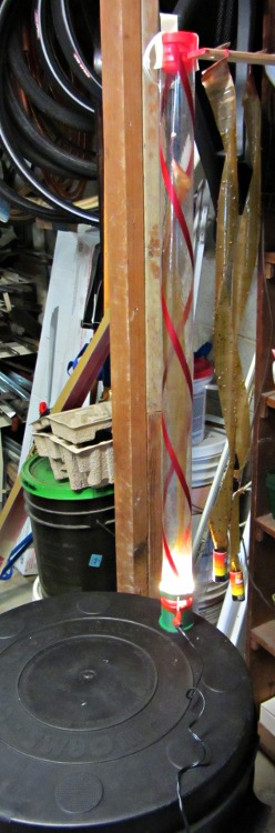
    Flies like heat and light, while worms vastly prefer cool and dark, so the general idea is to drill a hole in the bin lid, fit a long tube over it, put an LED ring light at the base, and run a flypaper spiral up the tube to a vent cap near the top. The first picture gives an overview, although it’s tough to see the vertical tube against the clutter: it’s clear with two red spirals, having started life as some weird-ass holiday decoration for the previous owners of our house.

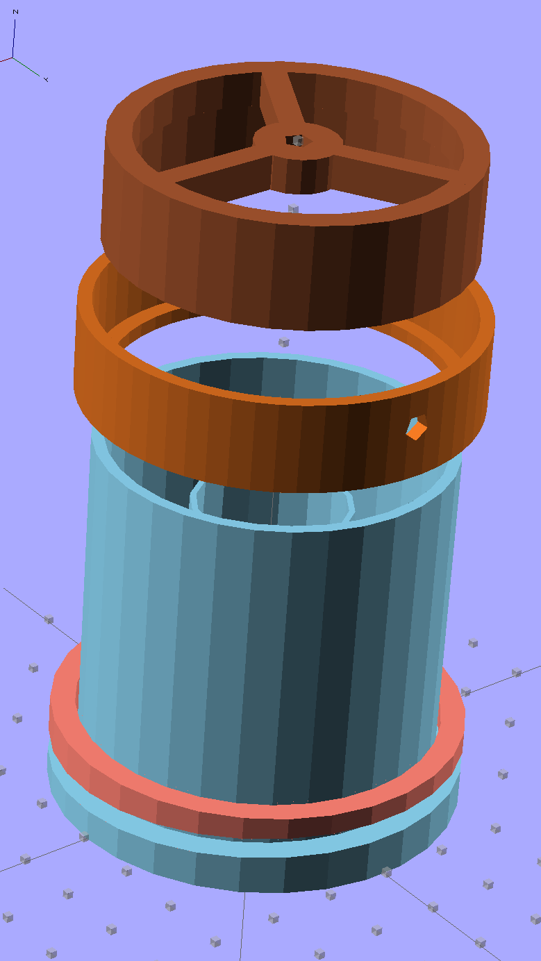
    Anyhow, the more interesting plastic bits look like this:
    Fly Escape - solid model
    Fly Escape – solid model

    The top ring is the vent cap, with a hole in the middle for a string supporting the sticky tape strip. The middle ring holds three sections of LED strip light that dissipate about 2 W from a 12 V wall wart; that’s enough heat around the tube to produce a slight upward draft. The riser tube at the bottom has an angled rim that compensates for the bin lid angle and holds the long tube vertical. The ring around the riser has a matching angle.

    They fit into the lid thusly:

    Fly Escape - Riser trial fit
    Fly Escape – Riser trial fit

    Two beads of hot-melt glue, top and bottom, hold them in place and make an air- / worm- / fly-tight seal.

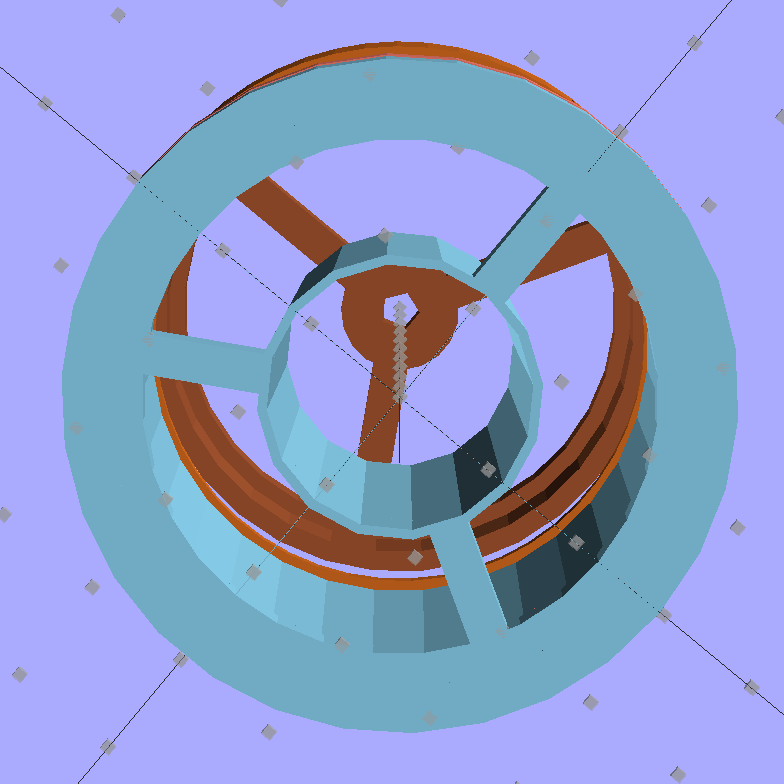
    The inner tube holds the fly paper container and has a slight inward taper toward the top to wedge it in place:
    Fly Escape - solid model - bottom
    Fly Escape – solid model – bottom

    A similar view from inside the actual lid:
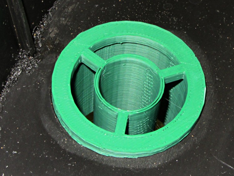
    Fly Escape - Riser trial fit - bottom
    Fly Escape – Riser trial fit – bottom

    That was the first pass at the dimensions; the tube walls didn’t quite join because I forgot to force the number of polygonal sides to be equal. It’s deliberately thin to make the walls springy, but everything must be Just Right to get both no fill and no space between the two perimeter threads.

    The riser and LED ring, combined with festive spiral stripes along the tube and some silicone tape sealing the tubes together, produce a cheery nuclear glow that’s enhanced by the victims mired in the adjacent flypaper strips. A third strip runs up the middle of the tube:
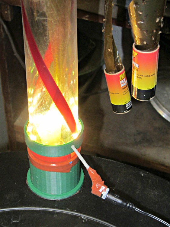
    Fly Escape in action
    Fly Escape in action

    The vent cap on the top of the tube has a small hole in the middle to hold the string supporting the flypaper spiral exactly in the middle of the tube. This view is upside-down from the mounted orientation :
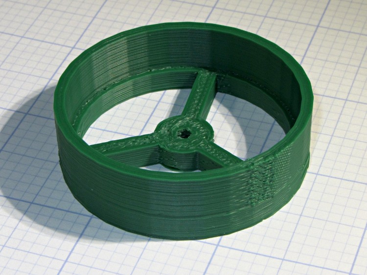
    Fly Escape - Vent Cap
    Fly Escape – Vent Cap

    The alert reader will notice a red top plug in place of the vent cap in the first picture. This whole project happened over the course of a frantic afternoon, evening, and morning, with progressive product improvements along the way. For example, it turns out that some flies went pedestrian and walked up the inside of the tube, so there’s now a circle of screening inside that nice vented cap.

    Having a 3D printer to hammer out custom plastic widgetry on a short schedule = win.

    The OpenSCAD source code:

    // Worm bin fly escape
    // Ed Nisley KE4ZNU - March 2012
    
    Layout = "Show";						// Build.. Show Riser Ring Cap
    
    //- Extrusion parameters - must match reality!
    
    ThreadThick = 0.25;
    ThreadWidth = 2.0 * ThreadThick;
    
    HoleFinagle = 0.3;
    HoleFudge = 1.00;
    
    function HoleAdjust(Diameter) = HoleFudge*Diameter + HoleFinagle;
    
    Protrusion = 0.1;						// make holes end cleanly
    
    //-- Dimensions
    
    RiserID = 47.0;							// ID = transparent riser tube OD
    RiserOD = 51.0;							// OD = hole in lid (matches hole saw OD)
    RiserHeight = 50.0;						// wall height from lid
    
    RiserSides = 4*8;						// for consistency & symmetry
    
    RiserBaseHeight = IntegerMultiple(5.0,ThreadThick);			// stop ring height
    RiserBaseID = RiserID - 2*1.0;								// stop ring ID
    
    LipOD = 59.0;							// OD of lip mounted on lid around tube
    LipAngle = 3.0;							// angle for lip to make tube vertical
    LipMinThick = IntegerMultiple(3.0,ThreadThick);		// min lip thickness
    LipAngleThick = LipOD*tan(LipAngle);				// angled section thickness
    LipThick = LipMinThick + LipAngleThick;				// total lip thickness
    
    RingClearance = 0.5;								// space between ring and tube
    
    TrapID = 23.0;							// sticky tape container OD
    TrapIDTaper = 2.0;						// taper to hold container in place
    TrapHeight = 45.0;						//  ... height
    TrapWallThickness = 2*ThreadWidth;
    TrapSides = 4*4;
    
    TrapFlanges = 3;						// number of support flanges
    TrapFlangeThick = IntegerMultiple(3.5,ThreadWidth);
    
    LEDThick = 2.5;							// LED strip thickness
    LEDWidth = 11.0;						//  ... width
    LEDWireOD = 3.0;						// power cable dia
    LightID = RiserID + 2*LEDThick;			// ID of LED collar
    LightOD = LightID + 2*4*ThreadWidth;		//  ... OD
    LightFlangeThick = IntegerMultiple(2.0,ThreadThick);
    
    CapID = RiserID;
    CapRingID = CapID - 2*1.5;
    CapOD = CapID + 2*4*ThreadWidth;
    CapBaseHeight = RiserBaseHeight;
    CapHeight = 10.0 + CapBaseHeight;
    CapSides = RiserSides;
    CapFlanges = 3;
    CapFlangeThick = TrapFlangeThick;
    CapGuideID = 3.0;
    CapGuideOD = CapGuideID + 6*ThreadWidth;
    
    //-- Sticky tape container holder
    
    module TrapMount() {
    
      ODBot = TrapID + 2*TrapWallThickness;
      ODTop = TrapID - TrapIDTaper + 2*TrapWallThickness;
    
      difference() {
    	union() {
    	  cylinder(r1=ODBot/2,r2=ODTop/2,h=TrapHeight,$fn=TrapSides);
    	  for (i=[0:TrapFlanges-1])
    		rotate(i*(360/TrapFlanges) + 90)			// align leg with thick side
    		  translate([RiserOD/4,0,RiserBaseHeight/2])
    			cube([(RiserOD/2 - 4*Protrusion),TrapFlangeThick,RiserBaseHeight],center=true);
    	}
    	translate([0,0,-Protrusion])
    	  cylinder(r1=HoleAdjust(TrapID)/2,
    			   r2=HoleAdjust(TrapID - TrapIDTaper)/2,
    			   h=(TrapHeight + 2*Protrusion),
    			   $fn=TrapSides);
      }
    
    }
    
    //-- Riser tube
    
    module RiserTube() {
    
      TotalHeight = RiserHeight + RiserBaseHeight;
    
      difference() {
    	cylinder(r=RiserOD/2,h=TotalHeight,$fn=RiserSides);
    	translate([0,0,RiserBaseHeight])
    	  PolyCyl(RiserID,TotalHeight,RiserSides);
    	translate([0,0,-Protrusion])
    	  cylinder(r=RiserBaseID/2,h=TotalHeight,$fn=RiserSides);
      }
    
    }
    
    //-- Angled lip around ring
    //		aligned with flat side downward at Z=0
    
    module LipRing(Clearance = 0.0) {
    
      difference() {
    	cylinder(r=LipOD/2,h=LipThick);
    	translate([0,0,-Protrusion])
    	  cylinder(r=(RiserOD/2 + Clearance),
    			   h=(LipThick + 2*Protrusion),
    			   $fn=RiserSides);
    	rotate([LipAngle,0,0])
    	  translate([-LipOD,-LipOD,(LipMinThick + LipOD/2*tan(LipAngle))])
    		cube([2*LipOD,2*LipOD,LipAngleThick],center=false);
      }
    }
    
    //-- Collar to hold LED strip light
    
    module LEDCollar() {
    
      difference() {
    	PolyCyl(LightOD,(LEDWidth + LightFlangeThick));
    	translate([0,0,LightFlangeThick])
    	  PolyCyl(LightID,(LEDWidth + Protrusion));
    	translate([0,0,-Protrusion])
    	  PolyCyl(RiserID,(LightFlangeThick + 2*Protrusion));
    	translate([0,0,(LightFlangeThick + LEDWidth/2)])
    	  rotate([0,90,90])
    		PolyCyl(LEDWireOD,LightOD);
      }
    }
    
    //-- Cap to hold trap string and vent the tube
    
    module VentCap() {
    
    	union() {
    	  difference() {
    		cylinder(r=CapOD/2,h=CapHeight,$fn=CapSides);
    		translate([0,0,-Protrusion])
    		  cylinder(r=CapRingID/2,h=(CapHeight +2*Protrusion),$fn=CapSides);
    		translate([0,0,CapBaseHeight])
    		  cylinder(r=CapID/2,h=CapHeight,$fn=CapSides);
    	  }
    	  difference() {
    		union() {
    		  for (i=[0:TrapFlanges-1])
    			rotate(i*(360/CapFlanges))
    			  translate([CapOD/4,0,CapBaseHeight/2])
    				cube([(CapOD/2 - 4*Protrusion),CapFlangeThick,CapBaseHeight],center=true);
    		  cylinder(r=CapGuideOD,h=CapBaseHeight);
    		}
    		translate([0,0,-Protrusion])
    		  PolyCyl(CapGuideID,CapHeight);
    	  }
    	}
    
    }
    
    //-- Handy routines
    
    function IntegerMultiple(Size,Unit) = Unit * ceil(Size / Unit);
    
    module PolyCyl(Dia,Height,ForceSides=0) {           // based on nophead's polyholes
    
      Sides = (ForceSides != 0) ? ForceSides : (ceil(Dia) + 2);
    
      FixDia = Dia / cos(180/Sides);
    
      cylinder(r=(FixDia + HoleFinagle)/2,h=Height,$fn=Sides);
    }
    
    //-- Put peg grid on build surface
    
    module ShowPegGrid(Space = 10.0,Size = 1.0) {
    
      Range = floor(50 / Space);
    
    	for (x=[-Range:Range])
    	  for (y=[-Range:Range])
    		translate([x*Space,y*Space,Size/2])
    		  %cube(Size,center=true);
    
    	for (z=[1:10])
    	  translate([0,0,z*Space])
    		  %cube(Size,center=true);
    }
    
    //- Build it
    
    ShowPegGrid();
    
    if (Layout == "Ring")
      LipRing();
    
    if (Layout == "Riser")
      RiserTube();
    
    if (Layout == "Cap")
      VentCap();
    
    if (Layout == "Show") {
      color("SkyBlue") {
    	TrapMount();
    	RiserTube();
    	LipRing();
      }
      color("Salmon")
    	translate([0,0,2*LipThick])
    	  rotate([180,0,0])
    		LipRing(RingClearance);
      color("Chocolate")
    	translate([0,0,(1.25*RiserHeight)])
    	  LEDCollar();
      color("Sienna")
    	translate([0,0,2*RiserHeight])
    	  rotate([180,0,0])
    		VentCap();
    }
    
    if (Layout == "Build1") {
      TrapMount();
      RiserTube();
      LipRing();
    }
    
    if (Layout == "Build2") {
    	LipRing(RingClearance);
    }
    
    if (Layout == "Build3") {
    	LEDCollar();
    }
    
    if (Layout == "Build4") {
    	VentCap();
    }
    
  • Dr. Who Cookie Cutters: First Light!

    Dr. Who and Tux Cookies
    Dr. Who and Tux Cookies

    The chefs produced fine cookies from those fine Thing-O-Matic objects.

    Although the economic argument for producing custom cookie cutters may not be persuasive, the fact that you (well, I) can produce custom widgets certainly is. Most of the things I build and repair don’t require great mechanical strength or finicky dimensional precision, so a DIY 3D printer is exactly the right hammer for the job.

    Now, if only I had a laser cutter

  • Harbor Freight Bar Clamp: Handle Hole Support Plugs

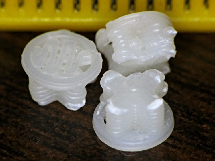
    Having printed up three of those handles for Show-n-Tell, I preemptively installed one in the hasn’t-failed-yet clamp, and poked the support out of another to show how it works. They’re just the cutest little buttons:

    HF bar clamp handle - support plug
    HF bar clamp handle – support plug

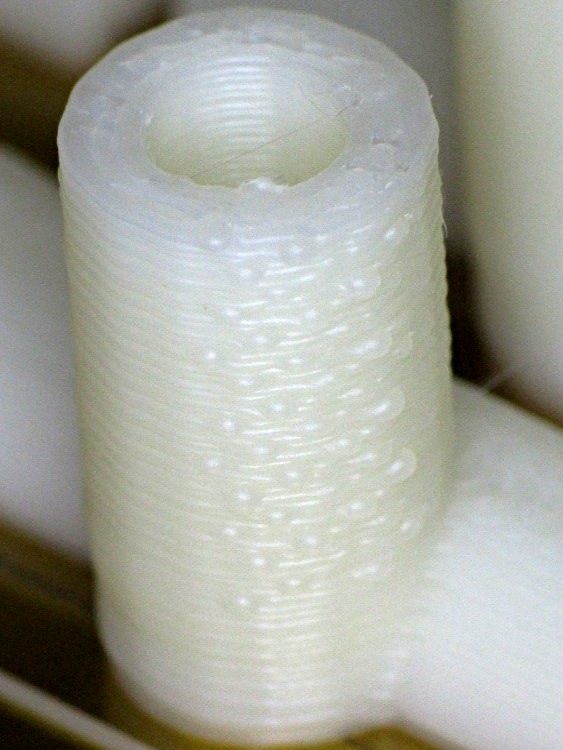
    The fins are a touch under 4.5 mm end-to-end and 1 mm (2 × 0.5 mm) across, with layer thickness = 0.25 mm. The first layer fill looks a bit lackadaisical, but the bottom of the surrounding handle came out glass-solid with barely visible joints between the threads, so the settings work fine for larger objects.

    HF Bar Clamp - support - solid model
    HF Bar Clamp – support – solid model

    The tip of each fin has a scar where the overlying perimeter thread bonded to it. Skeinforge is set to extrude the perimeter first, which would squirt that circle (well, pentagon) into mid-air… which is why this support plug lies in wait below.

  • Reversal Zits: Extruder Pressure vs. Flow vs. Acceleration

    Pondering the Reversal Zittage Bestiary led me to wonder about the formal relationship between pressure and flow in a viscous fluid passing through a nozzle. I’ll cheerfully admit my never-very-puissant fluid dynamics fu has become way rusty and, this being the first time I’ve collected all this stuff in one place, there’s certainly something I’m overlooking (to put it charitably), but here goes…

    Assuming that (semi-)molten plastic:

    Counterargument:

    The hot end contains about 20 mm of molten filament, which is 140 mm3 of 3 mm filament. During filament swaps, the filament pushes back about 2 mm = 14 mm3 without any external force, so there’s about 10% springiness in the hot end. That suggests the plastic really isn’t incompressible. Some of the springiness may come from the PTFE tube expanding against the surrounding metal tube, but the fact that the (solidified) molten zone has a larger diameter than the rest of the filament says the PTFE expansion is not very dynamic: the filament solidified at zero pressure.

    Boldly assuming incompressiblity anyway, the always-right-and-never-lies Wikipedia tells us that the equations of state boil down to the Stokes Equations, herewith directly cribbed:

    \boldsymbol{\nabla}p = \mu \nabla^2 \mathbf{u} + \mathbf{f}
    \boldsymbol{\nabla}\cdot\mathbf{u}=0

    That’s using this symbology, typographically modified to eliminate the need for embedded graphics:

    • The del operator represents the spatial gradient
    • ∇p = pressure gradient
    • u = fluid velocity
    • ∇·u = divergence of velocity (pointiness)
    • 2 u = Laplacian of velocity (sharpness of pointiness)
    • μ = dynamic viscosity
    • f = applied force

    Under the breathtakingly aggressive simplifying assumption that we can model slices across the extruder’s nozzle as nearly 2D radially symmetric pipes with a teeny frustum shape, we have a mostly one-dimensional situation:

    • The first equation says that axial pressure gradient is directly proportional to the applied force, which makes sense, plus a huge term due to the nozzle shape (how abruptly the velocity gradient changes)
    • The second equation is a generalization of GladOS‘s explanation of the conservation of momentum across Portal transfers: Speedy thing goes in, speedy thing comes out. For slightly conical slices, the axial speed increases as the radial area decreases, but the overall velocity gradient comes out zero.

    All the force f comes from a stepper motor ramming filament into the hot end:

    • To a good first order approximation, stepper motor torque is proportional to winding current.
    • For a given filament diameter, drive wheel diameter, and speed, a constant-current stepper applies constant force to the filament.
    • Stepper power being roughly constant for a given current, the available force varies inversely with rotational speed.

    Vigorous handwaving

    The low Reynolds number says the inertial forces don’t amount to squat, so everything depends on viscous flow. There’s nothing to accelerate; try accelerating a spoon through honey.

    Given a desired velocity u (mostly axial, for a particular extruding speed) and a nozzle, the first equation says the required force varies linearly with the pressure gradient ∇p. The gradient runs from atmospheric pressure on one end to the molten pool on the other, with the steepest change in the narrowest part of the nozzle. This suggests a short nozzle aperture is good.

    Conversely, a long smooth nozzle reduces ∇2 u by reducing abrupt velocity changes. For a given ∇p, the required force varies directly with the second (spatial) derivative of the velocity; lower velocity doesn’t mean lower force, but smoother changes (and their derivatives) certainly do.

    During reversal, the extruder must produce a negative ∇p very quickly to inhale the filament and prevent drooling. Assuming ∇p has the same order of magnitude in both directions (thus, different signs), changing the fluid velocity will produce huge changes in ∇2 u.

    Fluid compressibility means that, during the early part of the reversal operation, moving the filament doesn’t change the pressure by very much at all: the first equation remains pretty much constant.

    Caveats

    The Stokes equations are time-invariant: the velocity is a constant. So we’re looking at the steady state and making dangerous assumptions about changing conditions.

    The force variation seems linear with pressure gradient around a given flow, which is comforting: at least it’s not quadratic or something even more horrible.

    Given the low Reynolds number, even moderate flow variations should be roughly linear, as the velocity gradients won’t change much with changing velocity.

    This explains why Reversal Zittage gets so much worse at higher speeds: the extruder operates under constant (and, at least in my TOM, low) power that can keep pace with normal extrusion, but doesn’t have an order of magnitude more force in reserve for retraction.

  • Harbor Freight Bar Clamp: New Handle

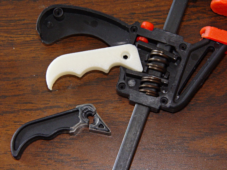
    Conjuring up a replacement handle for that broken Harbor Freight bar clamp turned out to be easier than I expected:

    HF bar clamp handle - installed
    HF bar clamp handle – installed

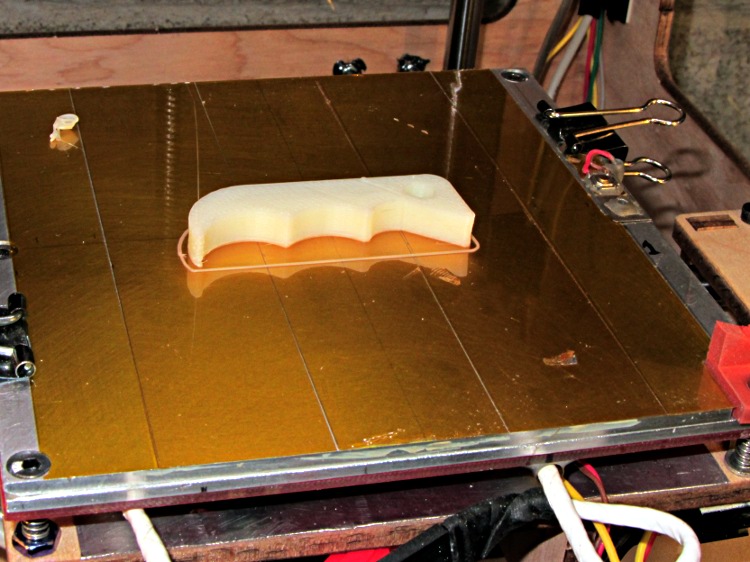
    The thing omits the original’s fancy edge rounding, because I just hit the finger grips with a rat-tail file after it cooled:

    HF bar clamp handle - build platform
    HF bar clamp handle – build platform

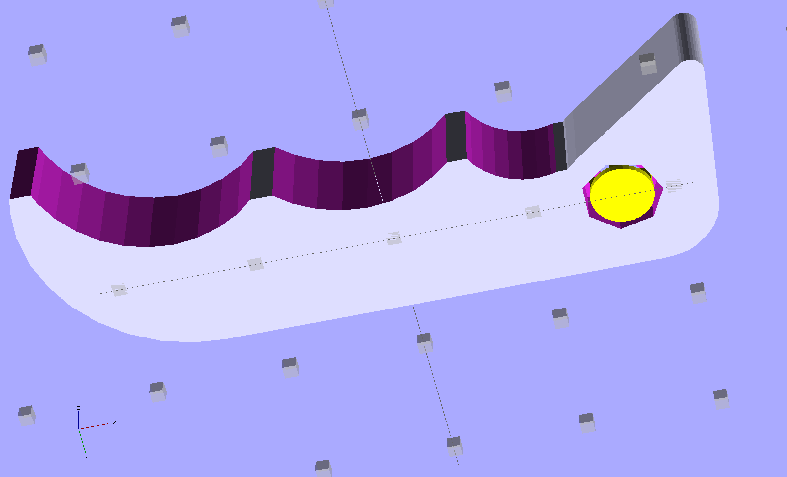
    The solid model uses OpenSCAD’s hull() operation for the beak and straight side of the handle, with a handful of circles chopping out the recesses. The rightmost arc lies tangent to the near side of the beak, so as to join without a stress-raiser bump:

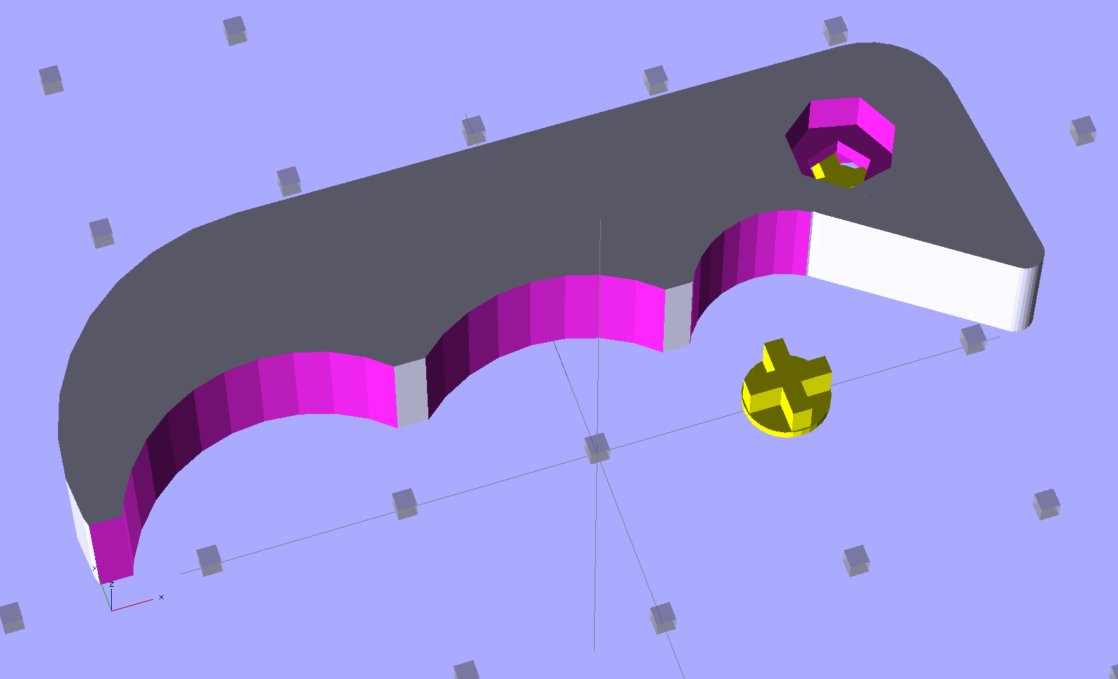
    HF Bar Clamp - support - solid model
    HF Bar Clamp – support – solid model

    The little yellow doodad is (a duplicate of) the support structure inside the pivot hole that prevents the middle section from drooping. It’s easier to see from the bottom:

    HF Bar Clamp - solid model - bottom
    HF Bar Clamp – solid model – bottom

    Removing the plug required nothing more than a fat pin punch and a whack from a brass hammer, with the plug centered over a hole in a random chunk of aluminum (with many other holes):

    HF bar clamp handle - support plug removed
    HF bar clamp handle – support plug removed

    Much to my delight, the holes & pivot recesses came out exactly the right size on the first version, with HoleWindage = 0.2. What’s new & different: that the first layer height has stabilized at 0.25 mm and the first few layers don’t get squished.

    I built three more handles in one setup, just to have some show-n-tell objects, with one prepped and on hot standby should the other Harbor Freight handle break. If these handles break, something aluminum on the Sherline will be in order.

    Now that clamp can go back into the collection. Puzzle: which one isn’t like the other ones?

    Too many bar clamps
    Too many bar clamps

    I should’a used Safety Orange filament, eh?

    [Update: xylitol designed a much better looking version that should be a drop-in replacement. Perhaps you can print it standing on edge (or end) to eliminate the support structures?]

    The OpenSCAD source code:

    // Handle for Harbor Freight bar clamp
    // Ed Nisley KE4ZNU - Jan 2012
    
    Layout = "Show";                // Build Show
    
    Support = true;
    SupportColor = "Yellow";
    
    //- Extrusion parameters must match reality!
    //  Print with +1 shells and 3 solid layers
    //  Use infill solidity = 0.5 or more...
    
    ThreadThick = 0.25;
    ThreadWidth = 2.0 * ThreadThick;
    
    HoleWindage = 0.2;
    
    Protrusion = 0.1;           // make holes end cleanly
    
    CircleSides = 4*8;
    $fn = CircleSides;
    
    //-------
    // Handle dimensions
    
    OALength = 49;
    OAThickness = 6.0;
    
    BodyWidth = 12;
    
    BeakRadius = 12;                            // hole to tip
    BeakEndRadius = 1.0;                        // roundness of tip
    BeakIncludedAngle = 40;
    BeakAngle = 55;
    BeakAdder = [2.0,1.0];                      // additional meat on outer and upper sides
    
    BeakHalfWidth = IntegerMultiple(BeakRadius*sin(BeakIncludedAngle/2),ThreadWidth);
    
    PivotXY = BeakRadius*[cos(BeakAngle),sin(BeakAngle)]; // pivot hole offset from beak tip
    
    PivotShaftDia = 2.6;
    PivotRecessDia = 5.0;
    PivotRecessDepth = 2.5;
    
    NumScallops = 3;
    ScallopRadius = [5,9,9];        // first scallop must be tangent to beak!
    ScallopX = [-((ScallopRadius[0] + BeakHalfWidth)*cos(90 - (BeakAngle - BeakIncludedAngle/2))),
                -17.5,-31.5];
    ScallopY = [-((ScallopRadius[0] + BeakHalfWidth)*sin(90 - (BeakAngle - BeakIncludedAngle/2))),
                -12,-12];
    
    echo(str("Scallops R=",ScallopRadius," X=",ScallopX," Y=",ScallopY));
    
    TailOuterRadius = 12;
    TailInnerRadius = 22;
    
    //-------
    
    function IntegerMultiple(Size,Unit) = Unit * ceil(Size / Unit);
    
    module PolyCyl(Dia,Height,ForceSides=0) {           // based on nophead's polyholes
    
      Sides = (ForceSides != 0) ? ForceSides : (ceil(Dia) + 2);
    
      FixDia = Dia / cos(180/Sides);
    
      cylinder(r=(FixDia + HoleWindage)/2,h=Height,$fn=Sides);
    }
    
    module ShowPegGrid(Space = 10.0,Size = 1.0) {
    
      Range = floor(50 / Space);
    
        for (x=[-Range:Range])
          for (y=[-Range:Range])
            translate([x*Space,y*Space,Size/2])
              %cube(Size,center=true);
    
    }
    
    //-------
    // Bits and pieces
    
    module Pivot() {
    
      translate([0,0,-Protrusion])
        PolyCyl(PivotShaftDia,(OAThickness + 2*Protrusion));
    
      translate([0,0,(OAThickness - PivotRecessDepth)])
        PolyCyl(PivotRecessDia,(PivotRecessDepth + Protrusion));
    
      translate([0,0,-Protrusion])
        PolyCyl(PivotRecessDia,(PivotRecessDepth + Protrusion));
    
    }
    
    module HandleBlock() {
    
      hull() {                            // beak
        cylinder(r=BeakHalfWidth,h=OAThickness);
        translate(BeakAdder)
          cylinder(r=BeakHalfWidth,h=OAThickness);
        translate([(PivotXY[0] - BeakEndRadius*cos(BeakAngle)),
                  -(PivotXY[1] - BeakEndRadius*sin(BeakAngle))])
          cylinder(r=BeakEndRadius,h=OAThickness);
      }
    
      hull() {                            // straight body edge
        translate(BeakAdder)
          cylinder(r=BeakHalfWidth,h=OAThickness);
        translate([-(OALength - PivotXY[0] - TailOuterRadius),BeakAdder[1]])
          cylinder(r=BeakHalfWidth,h=OAThickness);
      }
    
      translate([ScallopX[0],0,0])        // scalloped edge tips
        rotate(180)
          cube([(OALength - PivotXY[0] + ScallopX[0] - TailOuterRadius),
                (BodyWidth/2 - ThreadWidth),      // small Finagle constant = flat tips
                OAThickness],center=false);
    
      translate([-(OALength - PivotXY[0] - TailOuterRadius),        // tail
                (BeakHalfWidth + BeakAdder[1] - TailOuterRadius)])
        rotate(180)
          intersection() {
            cylinder(r=TailOuterRadius,h=OAThickness);
            translate([0,-TailOuterRadius])
              cube([TailOuterRadius,2*TailOuterRadius,OAThickness]);
          }
    
    }
    
    module SupportPlug() {
    
      color(SupportColor)
      union() {
        cylinder(r=IntegerMultiple((PivotRecessDia - ThreadWidth),ThreadWidth)/2,
                  h=2*ThreadThick);
        for (Index=[0,1])
          rotate(Index*90)
            translate([0,0,(PivotRecessDepth - ThreadThick)/2])
              cube([(PivotRecessDia - ThreadWidth - 2*Protrusion),
                    2*ThreadWidth,(PivotRecessDepth - ThreadThick)],
                  center=true);
      }
    }
    
    //------
    
    module Handle() {
    
        difference() {
          HandleBlock();
    
          translate([-(OALength - PivotXY[0] - TailOuterRadius),    // trim tail tip
                    -(PivotXY[1] - ThreadWidth),
                    -Protrusion])
            rotate(180)
              cube([TailOuterRadius,TailOuterRadius,(OAThickness + 2*Protrusion)]);
    
          for (Index=[0:NumScallops-1]) {
            translate([ScallopX[Index],ScallopY[Index],-Protrusion])
              cylinder(r=ScallopRadius[Index],h=(OAThickness + 2*Protrusion));
          }
    
          Pivot();
        }
    
        if (Support)                    // choose support to suit printing orientation
          SupportPlug();
    }
    
    //-------
    
    ShowPegGrid();
    
    if (Layout == "Show") {
      translate([OALength/3,10,0])
        Handle();
      translate([10,0,0])
        SupportPlug();
    }
    
    if (Layout == "Build")
      translate([OALength/3,0,0])
        Handle();
    

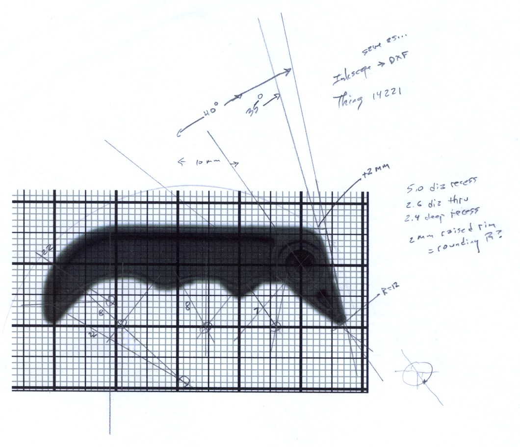
    The original doodles, which I started by scanning an unbroken handle and overlaying a grid, then scaling the grid so the end-to-end measurement worked out to the proper number of millimeters:

    Handle dimension doodles
    Handle dimension doodles
  • Skeinforge Feed Settings

    As part of the general reshuffling, I’ve started running the printer with different feeds for different functions:

    • Travel = 250 mm/s (non-printing!)
    • Basic rate = Infill = 60 mm/s (SF Speed plugin → Feed Rate)
    • Perimeter = 0.33 → 20 mm/s
    • First layer Infill = 0.25 → 15 mm/s
    • First layer Perimeter = 0.15 → 9 mm/s

    All of the corresponding Flow rates have the same values, which seems to be the right way to go. In Skeinforge 45, these are all collected in the Speed plugin.

    The very slow first layer ensures good adhesion to the Kapton build surface, with the rebuilt HBP now maintaining a very stable 0.25 mm across the whole platform. I’ll try goosing the first layer infill to 20 mm/s and the perimeter to 15 mm/s at some point, but this is entirely tolerable; I’d rather have it Just Work than occasionally come unstuck.

    The 20 mm/s perimeter reduces the Extruder Zittage problem, with the 9 mm/s Perimeter on the first layer coming out entirely zit-free. However, the sequential version of Amdahl’s Law applies here: a slow perimeter around a fast infill produces a fairly slow overall layer. Making the infill rather sparse doesn’t help, of course, but overall it’s a win.

    This collection of speeds hopelessly confuses Pronterface’s estimated print time calculation; the most amazing prediction reported just under 24 hours for a fairly simple set of objects that took maybe half an hour. A recent gizmo had an estimated time of 4:34 and an actual time of 28:07, off by a factor of 6.2. If Pronterface divides the total filament length by the first speed it finds in the file, it’d be off by a factor of 6.7, so maybe that’s close to what happens under the covers.

  • Reversal Zits: Speed, Acceleration, and a Bestiary

    The Skeinforge Dimension plugin subsumes the obsolete Reversal plugin’s features. At the end of each thread, if the nozzle will move more than the Minimum Travel distance (1 mm by default, which is what I’m using) to the start of the next thread, the extruder yanks Retraction Distance of filament out of the hot end at the Retraction Speed.

    Some experimentation at 30 mm/s showed that 2 mm of filament would eliminate all drooling, 1.5 mm left thin threads, and 1.0 mm wasn’t nearly enough.

    Similar experimentation suggested 60 mm/s as the upper limit for Retraction Speed, with the SJFW acceleration limiting parameters set for 250 mm/s2. The usual extrusion speed isn’t much faster than a crawl, so the distance required to reach a backwards 60 mm/s is:

    dist = (60 mm/s)2 / (2 * 250 mm/s2) = 7.2 mm

    What that means, of course, is that the extruder doesn’t have enough torque to reach the programmed speed in the required distance. Assuming SJFW uses trapezoidal limiting, it will accelerate to some maximum speed at the halfway point and decelerate to a stop at the same rate. Pegging the midpoint at 1 mm, the extruder will reach a peak speed of:

    v = √(2 * 250 mm/s2 * 1 mm) = 22 mm/s

    In order to hit 60 mm/s in the middle of the retraction, the extruder must accelerate at:

    a = (60 mm/s)2 / (2 * 1 mm) = 1800 mm/s2

    Which requires way more torque than the piddly little motor I’m using can provide.

    While I could swap in that larger motor, crank the current up a bit, and goose the extruder acceleration, the current Reversal Zittage is small enough for my purposes. I’d rather expend that effort on doodling up a direct-drive extruder, but that’s on the back burner until something horrible happens to the current extruder.

    One easy alternative: lower the perimeter speed sufficiently far as to reduce the pressure in the hot end enough that the current speeds can suppress the zits. Notice the difference in the pix below; what you can’t see is that the first layer has no zittage whatsoever. Of course, that means the perimeter must trundle along at maybe 10 mm/s…

    Herewith, a Reversal Zittage bestiary at various perimeter speeds, with Dimension set as described above and these extrusion settings:

    • 0.25 mm layer height
    • 0.50 mm thread width
    • 60 mm/s infill
    • 250 mm/s travel

    A Dishwasher Rack Protector vertical tube at 30 mm/s:

    Rack protector - Reversal zits
    Rack protector – Reversal zits

    The tube’s interior had equivalent zits that cleaned out easily with a twist drill.

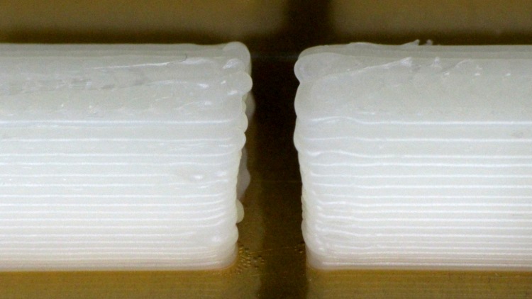
    Some of the half-tube ends came out slightly angled with zits here & there, but remember that they’re 4.5 mm tall:

    Rack protector - Reversal zits

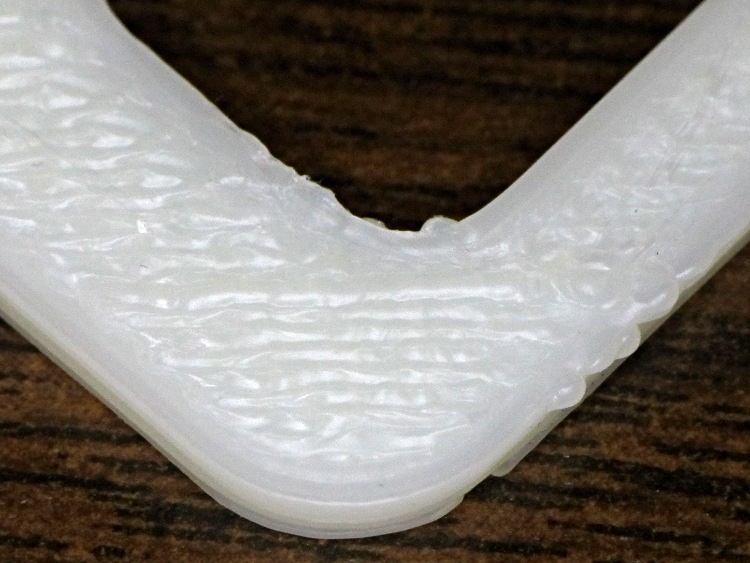
    The Zire 71 Protector had a lot more infill with very few perimeter joints. This corner shows a few zits at 30 mm/s:

    Zire 71 protector - Reversal zits
    Zire 71 protector – Reversal zits

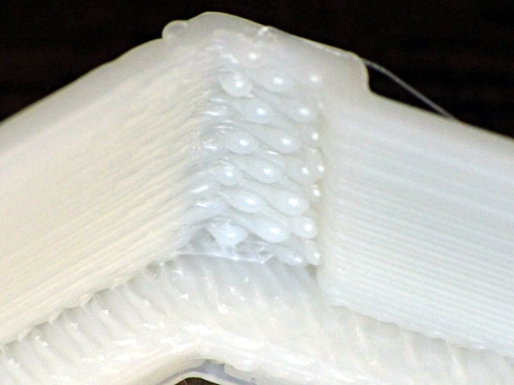
    One of the Dr. Who Cookie Cutters showed much more conspicuous zittage on the inside of a corner at 20 mm/s:

    Dr Who cutter - Reversal zit - interior corner
    Dr Who cutter – Reversal zit – interior corner

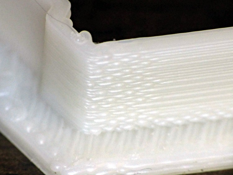
    Than on the outside of the same corner:

    Dr Who cutter - Reversal zit - Exterior corner
    Dr Who cutter – Reversal zit – Exterior corner

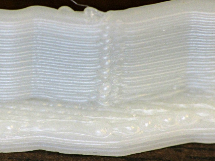
    The zits on the other cutter fell along one edge. The inside:

    Dr Who cutter - Reversal zits - interior side
    Dr Who cutter – Reversal zits – interior side

    And the outside:

    Dr Who cutter - Reversal zits - exterior side
    Dr Who cutter – Reversal zits – exterior side

    The Dr. Who set included flat cookie presses with patterns. Although these islands show some zittage, they’re about 1 mm tall and perhaps 5 mm long:

    Dr Who cutter - Reversal zits - islands
    Dr Who cutter – Reversal zits – islands

    The rest of the perimeter extrusions look essentially perfect, so these really are very minor imperfections.