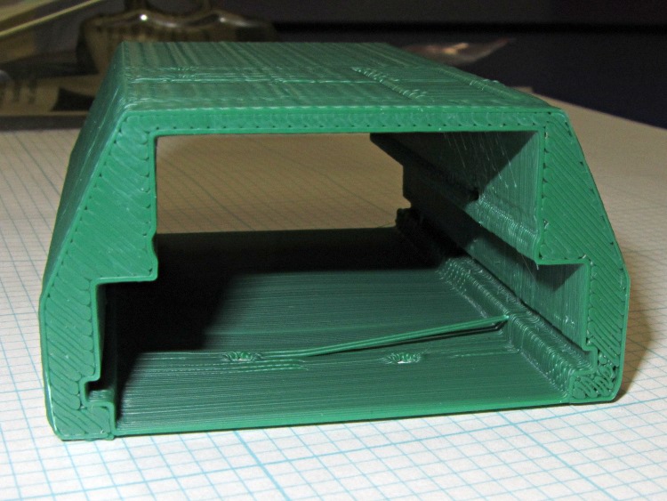
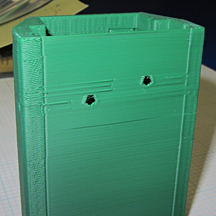
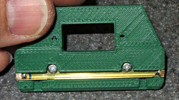
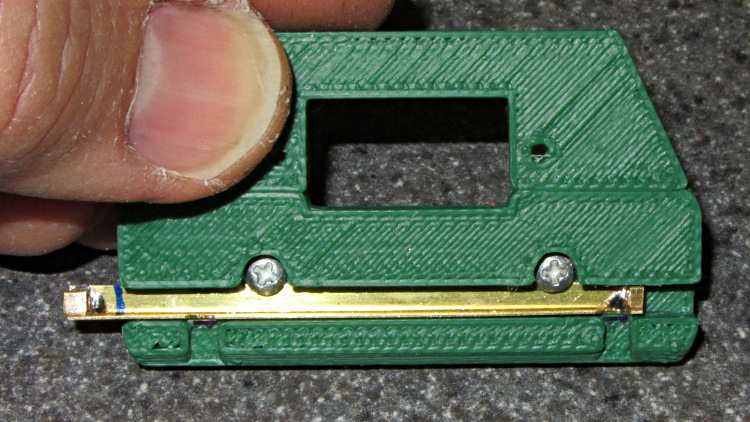
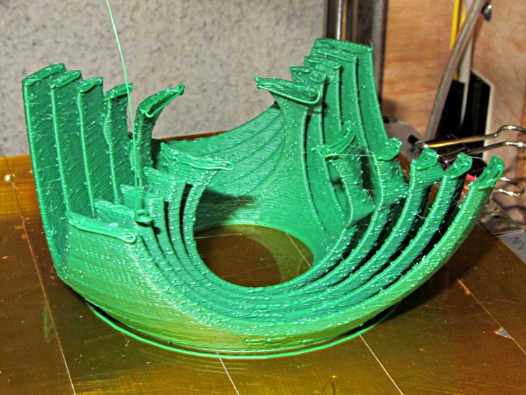
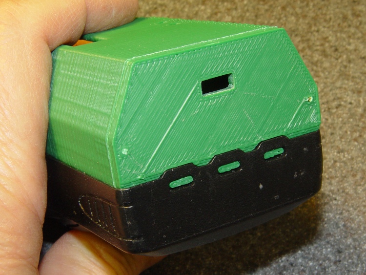
Rebuilding the case with some improvements to the original design came out much better:

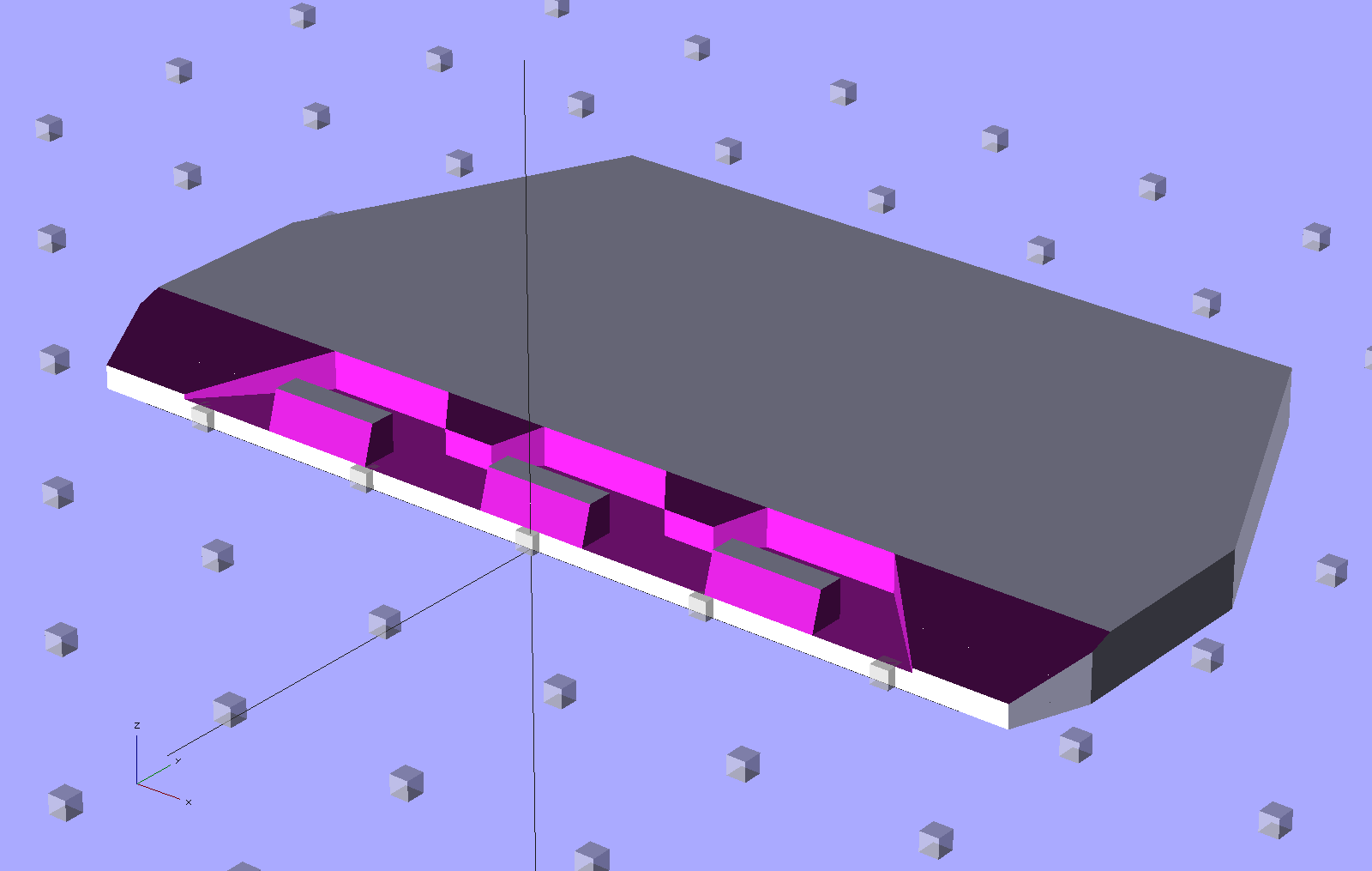
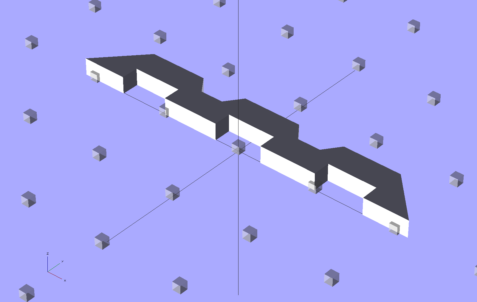
The latch is about the same as before, but the top endplate now has two cable ports and locating pins to take the force from the battery contact springs:

The bottom endplate has a hole for the TinyTrak3 Mode switch, plus two locating pins that hold the plate in place:
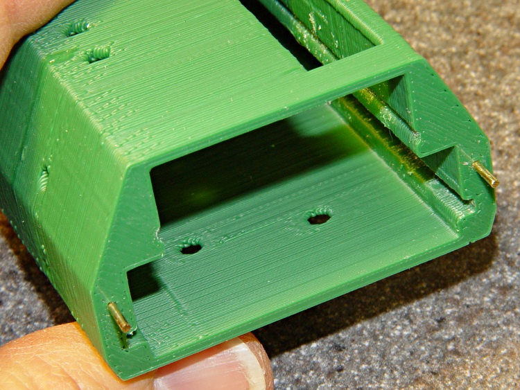
A detail shot of the two endplates shows the new holes:

Snippets of brass rod became locating pins, each slipped into a hole atop a dab of epoxy to lock it in place:
The boards slide in pretty much the way you’d expect:

The OpenSCAD code punches a third cable hole in the case for the HT wiring. I had high hopes that it would fit through the endplate, but …
Seen from the other end, there’s not much to see. The next case will have a slightly narrower LED opening:

The imperfection running down the side comes from a brief pause in the proceedings while the support plate fell out of the opening. As a consequence, I discovered that the LED window doesn’t need any support at all.
This view shows one of the battery contacts peeking through the hole for a yet-to-be-made stud:

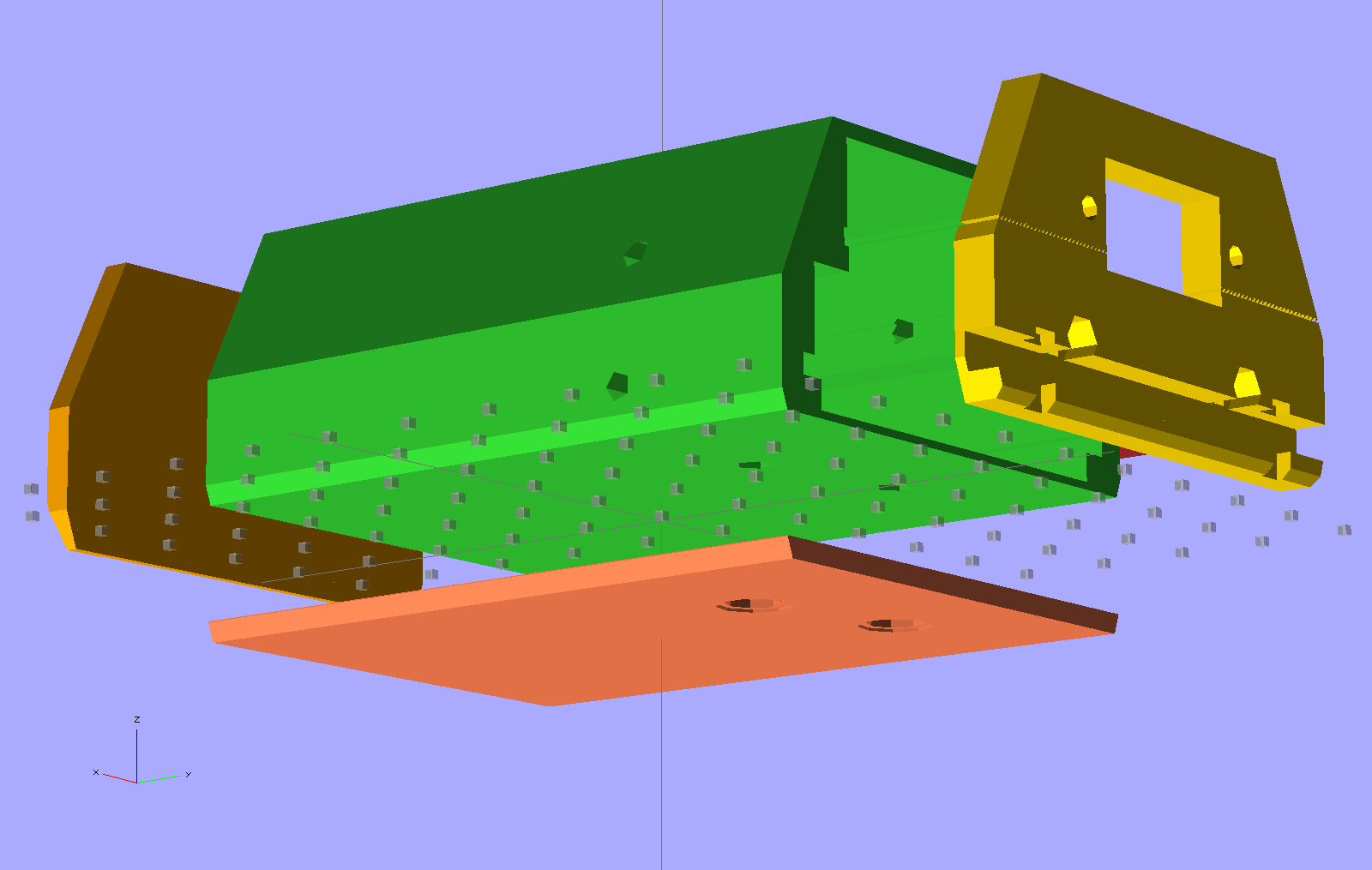
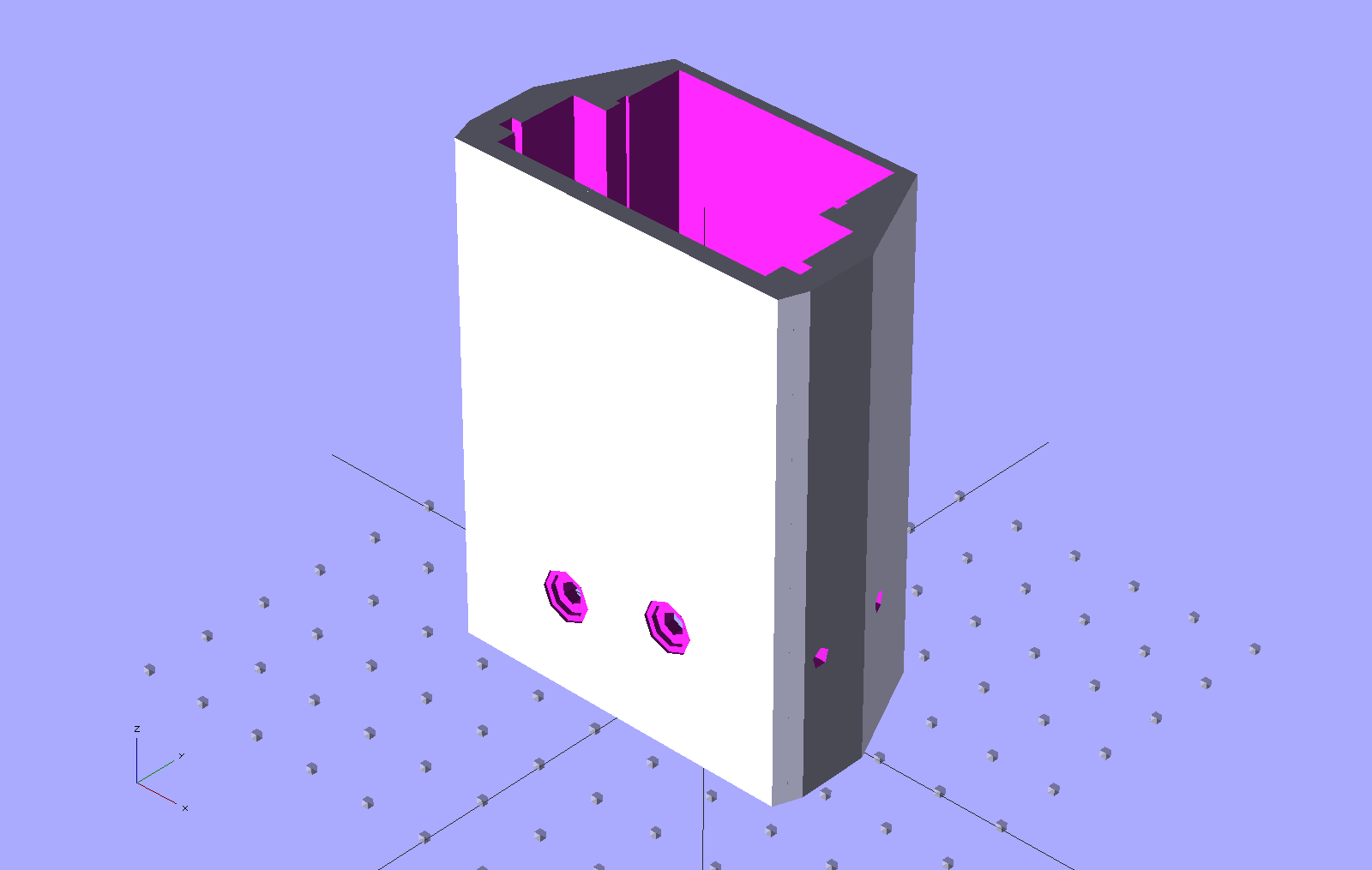
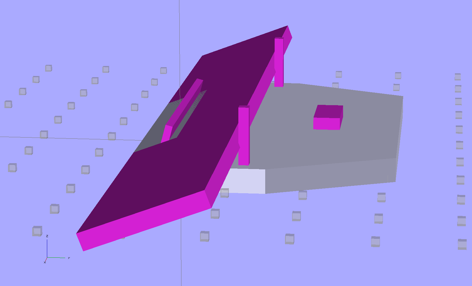
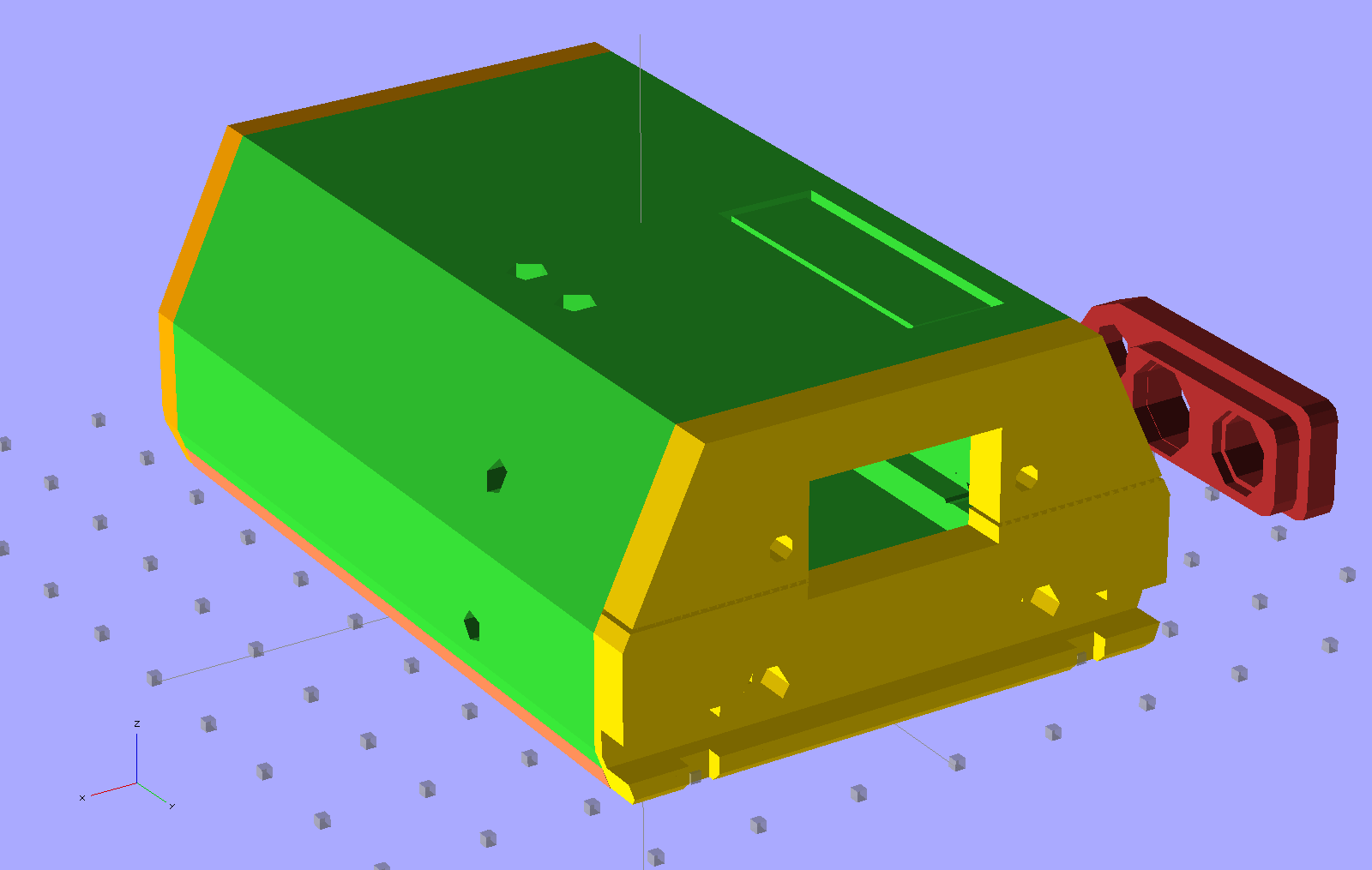
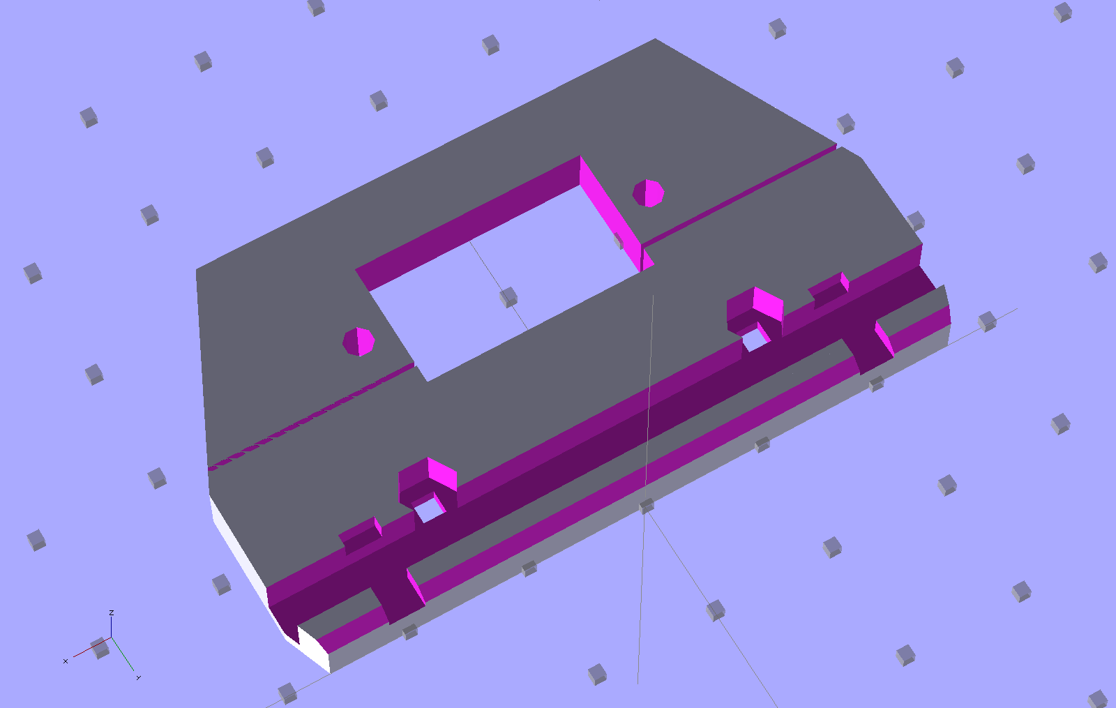
The solid model show some additional revisions, but it’s pretty close to the green plastic versions:

The OpenSCAD source code:
// Wouxun KB-UV3D Battery Pack Case
// Ed Nisley KE4ZNU April 2012

include </home/ed/Thing-O-Matic/lib/MCAD/units.scad>
include </home/ed/Thing-O-Matic/Useful Sizes.scad>

// Layout options

Layout = "Fit";
					// Overall layout: Fit Show
					// Printing plates: Build1 .. Buildn (see bottom!)
					// Parts: TT3 Audio DSub Shell Base Top
					// Shapes: RadioBase Contact
					// Speaker-mic mount: PlugPlate

ShowGap = 20;		// spacing between parts in Show layout

//- Extrusion parameters must match reality!
//  Print with +1 shells and 3 solid layers

ThreadThick = 0.25;
ThreadWidth = 2.0 * ThreadThick;

HoleWindage = 0.2;

function IntegerMultiple(Size,Unit) = Unit * ceil(Size / Unit);

Protrusion = 0.1;			// make holes end cleanly

//----------------------
//- Dimensions

CaseOverallHeight = 31.5;				// from battery surface, must clear PCBs!
CaseOverallWidth = 56;
CaseOverallLength = 80.25;				// inside of base to end of compartment

BatteryClearance = 1.5;					// contact seal height = air gap to compartment

// Interface to radio battery contacts
//	Length = shell length
//		calculated after everything else, so as to fill the compartment

PlateWidthMin = 53.0;
PlateWidthMax = 54.5;
PlateThick = IntegerMultiple(2.0,ThreadThick);
PlateAngle = atan(PlateThick/(PlateWidthMax/2 - PlateWidthMin/2));

ContactDia = 7.0;				// use rounded contact for simplicity
ContactRecess = IntegerMultiple(0.5,ThreadThick);	// recess for contact plate
ContactGapX = 10.5;				// X space between contacts
Contact1Y = 52.5;				// offset from base to edge of contact
Contact2Y = 56.5;
ContactStudDia = Clear4_40;
ContactStudHead = Head4_40;
ContactStudHeadThick = Head4_40Thick;

// Offsets from battery surface to PCB centerlines
//	TT3 must be above HT back shell for DB9 clearance
//	These must cooperate with the numbers in the case shell module

TT3Offset = 17.5 + PlateThick;
AudioOffset = 4.0 + PlateThick;

// Plate interface to base alignment holes and notches

BaseWidthInner = PlateWidthMin;
BaseWidthOuter = CaseOverallWidth;
BaseLength = CaseOverallHeight;					// perpendicular to battery surface
BaseThick = IntegerMultiple(1.0,ThreadThick);	// minimum sheet thickness below teeth
BaseWidthTaper = 5.0;							// ramp across entire width

BaseOpeningMax = 43.0;
BaseOpeningMin = 33.0;
BaseOpeningY = 5.3;
BaseOpeningDepth = IntegerMultiple(2.25,ThreadThick);

BaseTotalThick = BaseThick + BaseOpeningDepth;
echo("Base min thick: ",BaseThick," total: " ,BaseTotalThick);

BaseTabWidth = 6.0;
BaseTabThick = 2.0;
BaseTabGap = 7.0;
BaseTabOC = BaseTabWidth + BaseTabGap;
BaseToothSection = 3*BaseTabWidth + 2*BaseTabGap;

BaseToothBase = 5.8;
BaseToothTip = 2.8;
BaseToothThick = 2.0;
BaseToothAngle = atan(BaseOpeningDepth/0.6);
BaseToothOC = BaseTabOC;

WedgeAngle = atan(BaseWidthTaper/((BaseWidthOuter - BaseWidthInner)/2));

BaseEndLip = ThreadThick;			// should be 0.25 mm or so
BaseEndWidth = (PlateWidthMin - 3*BaseToothBase - 2*BaseToothTip)/2;
BaseEndAngle = atan((BaseOpeningDepth - BaseEndLip)/BaseOpeningY);

SwitchBody = [8.6,3.7,3.3];			// mode switch

// Plate interface to HT battery latch, cables, and connectors

TopThick = IntegerMultiple(5.5,ThreadThick);	// plate thickness for stiffness behind latch bar
echo("Top plate thick: ",TopThick);

DB9Recess = TopThick - 4.0;			// recess to max TT3 PCB clearance behind DB9 plate

TabEngageLength = 1.6;				// tab engaging surface length
TabWidth = 3.0;						//  ... width
TabEngageHeight = 4.5;				//  ... above battery compartment floor
TabHeight = 7.5;					// tab ramp top above battery compartment floor
TabOC = 40.0;

LatchBarWidth = 3.4;				// sliding latch mechanism (brass L stock)
LatchBarDepth = 3.4;
LatchBarThick = 0.35;

echo(" ... minimum: ",TopThick - LatchBarDepth);

SplitOffset = TT3Offset - 3.5;

TopBevel = 1.0;						// bevel at top of battery compartment
TopBevelAngle = 45;

PinOffsetWidth = 2.5;				// choose to center in sides of case shell
PinOffsetHeight = 12.0;				// above baseplate bottom
PinDepth = 7.0;						// into case shell
PinDia = 1.2;

ShellLength = CaseOverallLength - BaseThick - TopThick;

echo("Shell length: ",ShellLength);

// Speaker-mic plug plate

PlugBaseThick = 2.5;				// recess depth
PlugFillThick = 3.0;				// outer plate thickness

//----------------------
// Useful routines

module PolyCyl(Dia,Height,ForceSides=0) {			// based on nophead's polyholes

  Sides = (ForceSides != 0) ? ForceSides : (ceil(Dia) + 2);

  FixDia = Dia / cos(180/Sides);

  cylinder(r=(FixDia + HoleWindage)/2,
           h=Height,
	   $fn=Sides);
}

module ShowPegGrid(Space = 10.0,Size = 1.0) {

  Range = floor(50 / Space);

	for (x=[-Range:Range])
	  for (y=[-Range:Range])
		translate([x*Space,y*Space,Size/2])
		  %cube(Size,center=true);

}

//-------------------
// Component parts

//-----
// TinyTrak3+ PCB and component envelope
//	Some dimensions should feed into the case shell, but don't

module TinyTrak3(Length = 1.0) {

PCBThick = 1.6;
PCBWide = 36.5;
TopHigh = 9.5;
TopWide = PCBWide - 1.5;
BotHigh = 2.5;
BotWide = 35.0;

PCBx = PCBWide/2;
PCBy = (PCBThick + HoleWindage)/2;
URx = TopWide/2;
URy = PCBy + TopHigh;
LRx = BotWide/2;
LRy = PCBy + BotHigh;

  linear_extrude(height=Length,center=false,convexity=2) {
	polygon(points=[[URx,URy],[URx,PCBy],[PCBx,PCBy],[PCBx,-PCBy],[LRx,-PCBy],[LRx,-LRy],
					[-LRx,-LRy],[-LRx,-PCBy],[-PCBx,-PCBy],[-PCBx,PCBy],[-URx,PCBy],[-URx,URy]
				   ]);
  }
}

//-----
// Interface PCB and component envelope
//	Some dimensions should feed into the case shell, but don't

module AudioInterface(Length = 1.0) {

PCBThick = 2.0;
PCBWide = 49.5;
TopHigh = 9.0 + Protrusion;
TopWide = 46.0;
BotHigh = 3.0;
BotWide = 44.0;

PCBx = PCBWide/2;
PCBy = (PCBThick + HoleWindage)/2;
URx = TopWide/2;
URy = PCBy + TopHigh;
LRx = BotWide/2;
LRy = PCBy + BotHigh;

  linear_extrude(height=Length,center=false,convexity=2) {
	polygon(points=[[URx,URy],[URx,PCBy],[PCBx,PCBy],[PCBx,-PCBy],[LRx,-PCBy],[LRx,-LRy],
					[-LRx,-LRy],[-LRx,-PCBy],[-PCBx,-PCBy],[-PCBx,PCBy],[-URx,PCBy],[-URx,URy]
				   ]);
  }
}

//-----
// DB-9 (DE-9) panel opening
// http://www.interfacebus.com/Connector_D-Sub_Mechanical_Dimensions.html
//  DB-9 shell mounts on outside surface of case
// This is for the solder terminal side

module DSubMin9(Length = 1.0) {

Holex = 0.984/2 * inch;
HoleDia = Tap4_40;

URx = 0.769/2 * inch;
URy = 0.432/2 * inch;

	linear_extrude(height=Length,center=false,convexity=3) {
	  polygon(points=[[URx,URy],[URx,-URy],[-URx,-URy],[-URx,URy]]);
	  for (x = [-1,1]) {
		translate([x*Holex,0,0])
		  rotate(45) circle(r=(HoleDia + HoleWindage)/2,$fn=4);
	  }
	}

}

//-----
// Central case shape
//	This *should* depend directly on the circuit board sizes, but doesn't
//	The "Offset" parameters attempt to bottle up all the board sizes
//	Support in LED window must be hand-fit to work correctly... and isn't needed!

module CaseShell(Length=(ShellLength),Holes="true") {

// Polygon coordinates are in XY plane

URx = 40.0/2;
URy = CaseOverallHeight;

MRx = CaseOverallWidth/2;
MRy = 15.0;

LRx = CaseOverallWidth/2;
LRy = (LRx - PlateWidthMin/2)*tan(PlateAngle);

BRx = PlateWidthMax/2;
BRy = PlateThick - 0*Protrusion;

PRx = PlateWidthMin/2;				// combined battery plate
PRy = 0;

ScrewOffset = 20.0;					// from top end of case

LEDWindow = [30.0,5.0,6];			// with case aligned vertically
LEDOffset = [15,URy,(Length + TopThick - 25.0)];

TrimPot1 = [-14,TT3Offset,(Length + TopThick - 30)];
TrimPot2 = [-14,TT3Offset,(Length + TopThick - 37.5)];

HTCableDia = 3.2;
HTCableOffset = AudioOffset + HTCableDia/2 + 1.0;

  rotate([90,0,180])
	union() {
	  difference() {

		  linear_extrude(height=Length,center=false,convexity=5)
			polygon(points=[[URx,URy],[MRx,MRy],[LRx,LRy],[BRx,BRy],[PRx,PRy],
							[-PRx,PRy],[-BRx,BRy],[-LRx,LRy],[-MRx,MRy],[-URx,URy]]);

		if (Holes) {
		  translate([0,AudioOffset,-Protrusion])
			AudioInterface(Length + 2*Protrusion);

		  translate([0,TT3Offset,-Protrusion])
			TinyTrak3(Length + 2*Protrusion);

		  for (y = [TT3Offset,AudioOffset])
			translate([-CaseOverallWidth,y,(Length - ScrewOffset)])
			  rotate([0,90,0])
				rotate(0)					// Z rotation puts point upward for printing
				PolyCyl(Tap4_40,CaseOverallWidth);

		  translate(LEDOffset)
			rotate([90,90,0])
			  translate([-LEDWindow[0]/2,-LEDWindow[1]/2,-Protrusion])
			  cube(LEDWindow,center=false);

		  for (p = [TrimPot1,TrimPot2])
			translate(p)
			  rotate([-90,90,0])				// Y rotation puts point upward for printing
				PolyCyl(3.0,URy);

		  for (x=[-1,1]) {
			translate([x*(CaseOverallWidth/2 - PinOffsetWidth),
					  PinOffsetHeight,
					  (Length - PinDepth)])
			  rotate(45)						// align hole sides with case sides
				  PolyCyl(PinDia,2*TopThick);
			translate([x*(CaseOverallWidth/2 - PinOffsetWidth),
					  PinOffsetHeight,
					  -PlateThick])
			  rotate(45)						// align hole sides with case sides
				  PolyCyl(PinDia,(PlateThick + PinDepth));
		  }

		  translate([-(ContactGapX/2 + ContactDia/2),0,(Contact1Y + ContactDia/2)])
			rotate([90,0,0])
			  Contact();
		  translate([+(ContactGapX/2 + ContactDia/2),0,(Contact2Y + ContactDia/2)])
			rotate([90,0,0])
			  Contact();

		  translate([CaseOverallWidth/2,HTCableOffset,(Length - HTCableDia/2)])
			rotate([0,90,0])
			  cube([(HTCableDia + Protrusion),HTCableDia,CaseOverallWidth],center=true);
		}
	  }

if (false)
	  if (Holes)
		translate(LEDOffset)						// support plug in LED window
		  rotate([90,90,0])
			translate([-0.95*LEDWindow[0]/2,-0.80*LEDWindow[1]/2,ThreadWidth/2])
			  cube([0.95*LEDWindow[0],0.80*LEDWindow[1],2*ThreadWidth],center=false);

	}

}

//-----
// Battery contact recess
//  This gets subtracted from the bottom plate in two places
// 	Align points to print upward

module Contact() {

if (true)
  union() {													// vertical printing with case
	translate([0,0,-(ContactRecess + Protrusion)/2])
	  PolyCyl(ContactDia,(ContactRecess + Protrusion),8);
	translate([0,0,-(PlateThick + Protrusion)])
	  rotate(60/2)
	  PolyCyl(ContactStudDia,PlateThick,6);
	translate([0,0,-(ContactRecess + ContactStudHeadThick/3)])
	  PolyCyl(ContactStudHead,ContactStudHeadThick,8);				// allow for solder blob
  }
else
    union() {												// horizontal printing alone
	translate([0,0,-(ContactRecess - Protrusion)/2])
	  PolyCyl(ContactDia,(ContactRecess + Protrusion),8);
	translate([0,0,-(PlateThick + Protrusion)])
	  PolyCyl(ContactStudDia,(PlateThick + 2*Protrusion));
	translate([0,0,-(ContactRecess + ContactStudHeadThick/3)])
	  PolyCyl(ContactStudHead,ContactStudHeadThick,8);				// allow for solder blob
  }

}

//-----
// Radio bottom locating feature
//  This polygon gets subtracted from the battery pack base

module RadioBase() {

linear_extrude(height=(BaseOpeningDepth + Protrusion),center=false,convexity=5)
  polygon(points=[
			[-BaseOpeningMax/2,-Protrusion],

			[-BaseOpeningMin/2,BaseOpeningY],
			[-(BaseToothOC/2 + BaseToothBase/2),BaseOpeningY],

			[-(BaseToothOC/2 + BaseToothTip/2),(BaseOpeningY - BaseToothThick)],
			[-(BaseToothOC/2 - BaseToothTip/2),(BaseOpeningY - BaseToothThick)],
			[-(BaseToothOC/2 - BaseToothBase/2),BaseOpeningY],

			[ (BaseToothOC/2 - BaseToothBase/2),BaseOpeningY],
			[ (BaseToothOC/2 - BaseToothTip/2),(BaseOpeningY - BaseToothThick)],
			[ (BaseToothOC/2 + BaseToothTip/2),(BaseOpeningY - BaseToothThick)],
			[ (BaseToothOC/2 + BaseToothBase/2),BaseOpeningY],
			[ BaseOpeningMin/2,BaseOpeningY],

			[ BaseOpeningMax/2,-Protrusion],

			[ (BaseTabOC + BaseTabWidth/2),-Protrusion],
			[ (BaseTabOC + BaseTabWidth/2),BaseTabThick],
			[ (BaseTabOC - BaseTabWidth/2),BaseTabThick],
			[ (BaseTabOC - BaseTabWidth/2),-Protrusion],

			[ BaseTabWidth/2,-Protrusion],
			[ BaseTabWidth/2,BaseTabThick],
			[-BaseTabWidth/2,BaseTabThick],
			[-BaseTabWidth/2,-Protrusion],

			[-(BaseTabOC + BaseTabWidth/2),-Protrusion],
			[-(BaseTabOC + BaseTabWidth/2),BaseTabThick],
			[-(BaseTabOC - BaseTabWidth/2),BaseTabThick],
			[-(BaseTabOC - BaseTabWidth/2),-Protrusion],
		  ],
		  convexity=5
  );
}

//-----
// Battery pack base

module Base() {

  difference() {

	rotate([-90,180,0])
	  CaseShell(BaseTotalThick,false);

	translate([0,0,BaseThick])
	  RadioBase();

	translate([-BaseWidthOuter,-(BaseThick + BaseEndLip)/tan(BaseEndAngle),0])
	  rotate([BaseEndAngle,0,0])
		difference() {
		  cube([2*BaseWidthOuter,3*BaseOpeningY,BaseOpeningDepth],center=false);
		  translate([(BaseWidthOuter - (BaseToothSection + 2*Protrusion)/2),0,0])
			cube([(BaseToothSection + 2*Protrusion),1.2*BaseOpeningY,BaseOpeningDepth],center=false);
		}

	translate([0,0,BaseThick])
	  rotate([(-90 + BaseToothAngle),0,0])
		translate([0,-0.5,0])
		  cube([(BaseToothSection + 2*Protrusion),1.0,10],center=true);

	for (x=[-1,1])
	  translate([x*(CaseOverallWidth/2 - PinOffsetWidth),PinOffsetHeight,-Protrusion])
		rotate(45)						// align hole side with plate side
		  PolyCyl(PinDia,2*TopThick);

	translate([(-SwitchBody[0]/2),TT3Offset,-SwitchBody[2]/2])
	  scale([1,1,2])
		cube(SwitchBody);

  }
}

//-----
// Top plate with latch
//	Split around TinyTrak3 serial connector
//	 ... which must be at the same height as in the shell!
//	The cable hole sizes & locations are entirely ad-hoc

module TopPlate() {

Cable1Dia = 5.0;
Cable2Dia = 5.0;
CableHoleLength = TopThick + 2*Protrusion;
CableHoleZ = -Protrusion;

DB9Plate = [32.0,13.5,1.25];					// plate surrounding connector body

  difference() {

	rotate([-90,180,180])
	  CaseShell(TopThick,false);

	translate([0,-TT3Offset,-Protrusion])
	  DSubMin9(TopThick + 2*Protrusion);

	translate([0,-TT3Offset,(TopThick - DB9Plate[2]/2)])
	  cube([DB9Plate[0],DB9Plate[1],(DB9Plate[2] + Protrusion)],center=true);

	translate([-CaseOverallWidth,-SplitOffset,-2*Protrusion])		// split the plate
	  cube([2*CaseOverallWidth,4*Protrusion,(TopThick + 2*Protrusion)]);

	translate([0,0,(TopThick - TopBevel)])
	  rotate([-TopBevelAngle,0,0])
		translate([-CaseOverallWidth,-TopThick,0])
		  cube([2*CaseOverallWidth,2*TopThick,2*TopThick],center=false);

	for (x=[-1,1])
	  translate([(x*TabOC/2),
				(-TabHeight/2 + Protrusion),
				(TopThick - TabEngageLength/2 + Protrusion/2)])
		rotate([90,0,0])
		  cube([TabWidth,
				(TabEngageLength + Protrusion),
				(TabHeight + Protrusion)],center=true);

	translate([-CaseOverallWidth,
			  -(TabEngageHeight + LatchBarWidth - BatteryClearance),
			  (TopThick - LatchBarDepth)])
	  cube([2*CaseOverallWidth,(LatchBarWidth + LatchBarThick),(LatchBarDepth + Protrusion)]);

	for (x=[-1,1])
	  translate([(x*CaseOverallWidth/4),
				-(TabEngageHeight + LatchBarWidth + Clear2_56/2 - BatteryClearance + Protrusion),
				0]) {
		translate([0,0,-Protrusion])
		  rotate(45)						// align sides with slot
			PolyCyl(Tap2_56,(TopThick + 2*Protrusion));
		translate([0,0,(TopThick - LatchBarDepth)])
		  rotate(60)						// align sides with slot
			PolyCyl((Head2_56 + Protrusion),TopThick,6);		// extra extra clearance
	  }

	for (x=[-1,1])
	  translate([x*(CaseOverallWidth/2 - PinOffsetWidth),-PinOffsetHeight,-Protrusion])
		rotate(45)						// align hole side with plate side
		  PolyCyl(PinDia,2*TopThick);

	for (x=[-1,1])						// coincidentally line up with latch tabs
	  translate([(x*TabOC/2),-(SplitOffset - 3.0),-Protrusion])
		scale([1,1.7,1])
		  PolyCyl(Cable1Dia,CableHoleLength,6);
  }

}

//-----
// Speaker-Mic plug mounting plate

module PlugPlate() {

JackOC = 11.20;						// 14.25 OD - (3.58 + 2.58)/2

JackScrewDia = 4.6;
JackScrewOffsetX = 1.00;
JackScrewOffsetY = 5.25;			//  mounting screw to edge of lower recess

PlugBaseWidth = 9.25;				// lower section of plate
PlugBaseLength = 22.0;
PlugBaseRadius = 1.75;

Plug3Offset = 5.25;					// edge of base recess to 3.5 mm jack

Plug2BezelDia = 7.1;				// 2.5 mm plug
Plug2BezelThick = 1.04;
Plug2ScrewDia = 6.0;
Plug3ScrewLength = 3.0;

Plug3BezelDia = 8.13;				// 3.5 mm plug
Plug3BezelThick = 1.6;
Plug3ScrewDia = 7.95;
Plug3ScrewLength = 4.0;

PlugFillOffsetX = JackScrewOffsetX - 0.5;		// base recess CL to fill CL
PlugFillOffsetY = -10.5;				//  ... to edge of fill plate
PlugFillWidth = 11.0;
PlugFillLength = 34.00;
PlugFillRadius1 = 1.5;
PlugFillRadius2 = 4.5;

PlugFillOffsetYTotal = 0;

  BaseX = PlugBaseWidth/2 - PlugBaseRadius;
  BaseY = PlugBaseLength/2 - PlugBaseRadius;

  difference() {
	union() {
	  linear_extrude(height=PlugBaseThick,center=false,convexity=3)
		hull() {
		  translate([-BaseX,-BaseY,0])
			circle(r=PlugBaseRadius,$fn=8);
		  translate([-BaseX, BaseY,0])
			circle(r=PlugBaseRadius,$fn=8);
		  translate([ BaseX, BaseY,0])
			circle(r=PlugBaseRadius,$fn=8);
		  translate([ BaseX,-BaseY,0])
			circle(r=PlugBaseRadius,$fn=8);
		}

	  translate([PlugFillOffsetX,
				(PlugFillLength/2 - PlugBaseLength/2 + PlugFillOffsetY),
				PlugBaseThick])
		linear_extrude(height=PlugFillThick,center=false,convexity=5)
		  hull() {
			translate([0,-(PlugFillLength/2 - PlugFillRadius2),0])
			  circle(r=PlugFillRadius2,$fn=10);
			translate([-(PlugFillWidth/2 - PlugFillRadius1),-PlugBaseLength/2,0])
			  circle(r=PlugFillRadius1,$fn=8);
			translate([-(PlugFillWidth/2 - PlugFillRadius1),
					  (PlugFillLength/2 - PlugFillRadius1),0])
			  circle(r=PlugFillRadius1,$fn=8);
			translate([(PlugFillWidth/2 - PlugFillRadius1),
					  (PlugFillLength/2 - PlugFillRadius1),0])
			  circle(r=PlugFillRadius1,$fn=8);
			translate([(PlugFillWidth/2 - PlugFillRadius1),-PlugBaseLength/2,0])
			  circle(r=PlugFillRadius1,$fn=8);
		  }
	}

	translate([0,-JackOC/2,-Protrusion])
	  rotate(360/16) {
		PolyCyl(Plug3BezelDia,(Plug3BezelThick + Protrusion),8);
		PolyCyl(Plug3ScrewDia,(PlugBaseThick + PlugFillThick + 2*Protrusion),8);
	  }

	translate([0,+JackOC/2,-Protrusion])
	  rotate(360/16) {
		PolyCyl(Plug2BezelDia,(Plug2BezelThick + Protrusion),8);
		PolyCyl(Plug2ScrewDia,(PlugBaseThick + PlugFillThick + 2*Protrusion),8);
	  }

	translate([JackScrewOffsetX,-(PlugBaseLength/2 + JackScrewOffsetY),0])
	  PolyCyl(JackScrewDia,(PlugBaseThick + PlugFillThick + Protrusion));
  }

}

//-------------------
// Build things...

ShowPegGrid();

if (Layout == "TT3")
  TinyTrak3();

if (Layout == "Audio")
  AudioInterface();

if (Layout == "DSub")
  DSubMin9();

if (Layout == "Shell")
  CaseShell(CaseOverallLength);

if (Layout == "Top")
  TopPlate();

if (Layout == "Base")
  Base();

if (Layout == "RadioBase")
  RadioBase();

if (Layout == "PlugPlate")
  PlugPlate();

if (Layout == "Contact")
  rotate([180,0,0])
	Contact();

if (Layout == "Show" || Layout == "Fit") {

  translate([0,-ShellLength/2,0]) {

	translate([0,(Layout == "Show")?-ShowGap:0,0])
	  rotate([90,0,0])
		color("SandyBrown") Base();

	translate([0,0,0])
	    color("Olive") render() CaseShell();

	translate([-(CaseOverallWidth/2 + 10),50,CaseOverallHeight/2])
	  rotate([0,-90,0])
		color("Brown") PlugPlate();

	translate([0,((Layout == "Show")?(ShellLength + ShowGap):ShellLength),0])
	  rotate([-90,0,0])
		color("Chocolate") TopPlate();
  }
}

if (Layout == "Build1") {

  translate([0,-CaseOverallHeight/2,ShellLength])
	rotate([-90,0,0])
		CaseShell();

}

if (Layout == "Build2") {

    translate([5 + CaseOverallHeight,0,0])
	rotate([0,0,90])
	  Base();

  translate([-(5 + CaseOverallHeight),0,0])
	rotate(90)
	  TopPlate();

}

if (Layout == "Build3") {

  translate([0,0,(PlugBaseThick + PlugFillThick)])
	rotate([180,0,0])
	  PlugPlate();

}