The Smell of Molten Projects in the Morning

Ed Nisley's Blog: Shop notes, electronics, firmware, machinery, 3D printing, laser cuttery, and curiosities. Contents: 100% human thinking, 0% AI slop.

Tag: Thing-O-Matic

Using and tweaking a Makerbot Thing-O-Matic 3D printer

  • On Making Cookie Cutters

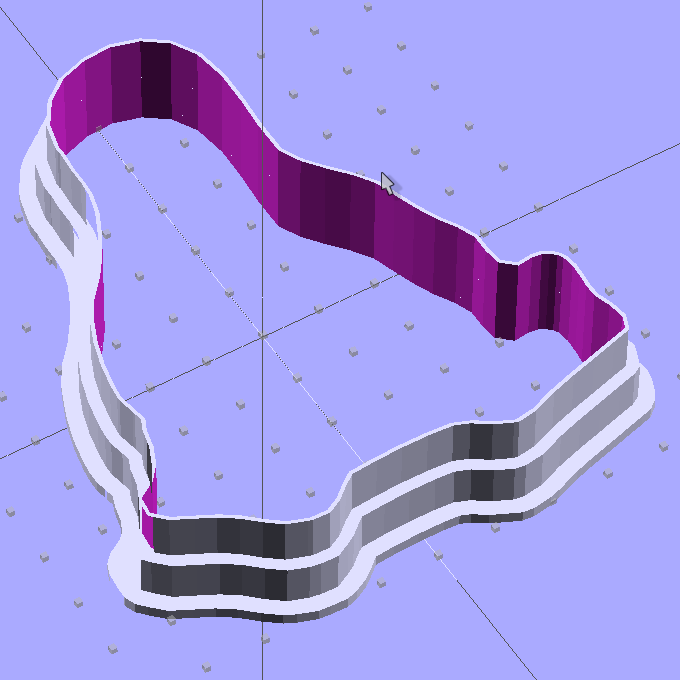
    Tux Cookie Cutter - solid model
    Tux Cookie Cutter – solid model

    Someone asked about how to convert a PNG file to a cookie cutter; she was stymied by some of the terminology and didn’t have a good overview of the process. I thought my reply might be useful to someone else.

    trying to understand how to create an STL file

    The key to understanding 3D printing is to realize that an STL file is just an intermediate step along the way from an idea to a plastic object. The real challenge is to create a 3D (aka “solid”) model of the object you want; after that, the rest follows more or less automatically.

    The overall process goes like this:

    1. Create a solid model (more on this below)
    2. Export the model as an STL file, usually by a menu selection
    3. Convert the STL file to G-Code using the printer control program
    4. Extrude plastic!

    Now, each step has many sub-steps, but that’s the Big Picture.

    You really don’t care about the STL or G-Code files, because they’re generated from the 3D model.

    take a png clipart image

    Because a PNG image represents a 2D (flat) drawing, it can contain grayscale (or color!) information that you may not want. Let’s start with just a simple black-and-white outline drawing that shows the outline of the cutter.

    The CAD program then “extrudes” that flat image into a 3D shape with a known height; I use OpenSCAD, but any 3D program should be able to do that trick. If you started with a PNG file of a circle, the extrusion will produce a 3D ring. If you start with an outline of Tux, you end up with an oddly shaped 3D ring.

    (Note that the term “extrusion” has two meanings. The CAD program extrudes the flat 2D image into a 3D model and the printer extrudes molten plastic to form the object. Gotta love the language!)

    Now that you have a basic 3D shape, you can fancy it up with thicker areas and handles and whatnot, but you could just print the shape and have a simple cookie cutter.

    Dr Who Cookie Cutters
    Dr Who Cookie Cutters

    If you’re making a cookie press, similar to those in the Dr Who cutters, then you start with a grayscale PNG (or JPG) and create a “height map” where the grayscale intensity determines the extrusion height: black = high and white = low (or the other way around). Again, any CAD program should be able to create a height map from a grayscale image.

    In fact, a black-and-white outline is just a simple version of a height map: it’s either tall (black) or short (white), with no levels in between.

    The height map becomes a 3D rectangle with one wavy side corresponding to the image. You join it with another rectangle to set the minimum thickness (you don’t want holes where the image was white), then add handles and suchlike.

    That’s how the Dr Who cutters work: a height map generated the flat press part and an outline generated the hollow cutter surrounding the press. The settings I used to print my copy may be helpful.

    You may have already seen my blow-by-blow description of converting an EPS drawing to the Tux cutter that starred in the movie.

    The process had far more complexity than it should, mostly because that old version of OpenSCAD had a few bugs that prevented me from using 2D-to-3D extrusion as I described above. The overall process was similar, though: start with a 2D shape, convert it into a long 3D rod, slice off a suitable length, then punch a hole in the middle.

    So, by and large, in order to make cookie cutters, you must master the “extrusion” part of 3D modeling. After you get a suitable 3D model of the cutter, then the rest will be easy! [grin]

    Hope that helps get you started…

  • KG-UV3D GPS+Voice Interface: APRS Bicycle Mobile

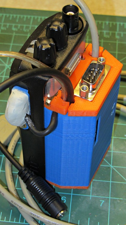
    Wouxun KG-UV3D with GPS-audio interface
    Wouxun KG-UV3D with GPS-audio interface

    Both of the GPS+voice interfaces for the Wouxun KG-UV3D radios have been working fine for a while, so I should show the whole installation in all its gory detail.

    If you haven’t been following the story, the Big Idea boils down to an amateur radio HT wearing a backpack that replaces its battery, combines the audio output of a Byonics TinyTrak3+ GPS encoder with our voice audio for transmission, and routes received audio to an earbud. Setting the radios to the APRS standard frequency (144.39 MHz) routes our GPS position points to the global packet database and, with 100 Hz tone squelch, we can use the radios as tactical intercoms without listening to all much of the data traffic.

    The local APRS network wizards approved our use of voice on the data channel, seeing as how we’re transmitting brief voice messages using low power through bad antennas from generally terrible locations. This wouldn’t work well in a dense urban environment with more APRS traffic; you’d need one of the newfangled radios that can switch frequencies for packet and voice transmissions.

    So, with that in mind, making it work required a lot of parts…

    Tour Easy - KG-UV3D GPS interface
    Tour Easy – KG-UV3D GPS interface

    A water bottle holder attaches to the seat base rail with a machined circumferential clamp. Inside the holder, a bike seat wedge pack contains the radio with its GPS+voice interface box and provides a bit of cushioning; a chunk of closed-cell foam on the bottom mostly makes me feel good.

    The flat 5 A·h Li-ion battery pack on the rack provides power for the radio; it’s intended for a DVD player and has a 9 V output that’s a trifle hot for the Wouxun radios. Some Genuine Velcro self-adhesive strips hold the packs to the racks and have survived surprisingly well.

    Just out of the picture to the left of the battery pack sits a Byonics GPS2 receiver puck atop a fender washer glued to the rack, with a black serial cable passing across the rack and down to the radio bag.

    A dual-band mobile antenna screws into the homebrew mount attached to the upper seat rail with another circumferential clamp. It’s on the left side of the rail, just barely out of the way of our helmets, and, yes, the radiating section of the antenna sits too close to our heads. The overly long coax cable has its excess coiled and strapped to the front of the rack; I pretend that’s an inductor to choke RF off the shield braid. The cable terminates in a PL-259 UHF plug, with an adapter to the radio’s reverse-polarity SMA socket.

    The push-to-talk button on the left handgrip isn’t quite visible in the picture. That cable runs down the handlebar, along the upper frame tube, under the seat, and emerges just in front of the radio bag, where it terminates in a 3.5 mm audio plug.

    The white USB cable from the helmet carries the boom mic and earbud audio over the top of the seat, knots around the top frame bar, and continues down to the radio. USB cables aren’t intended for this service and fail every few years, but they’re cheap and work well enough. The USB connector separates easily, which prevents us from being firmly secured to a dropped bike during a crash. I’d like much more supple cables, a trait that’s simply not in the USB cable repertoire. This is not a digital USB connection: I’m just using a cheap & readily available cable.

    All cables converge on the bag holding the radio:

    Tour Easy - KG-UV3D + GPS interface - detail
    Tour Easy – KG-UV3D + GPS interface – detail

    Now you can see why I put that dab of white on the top of the knob!

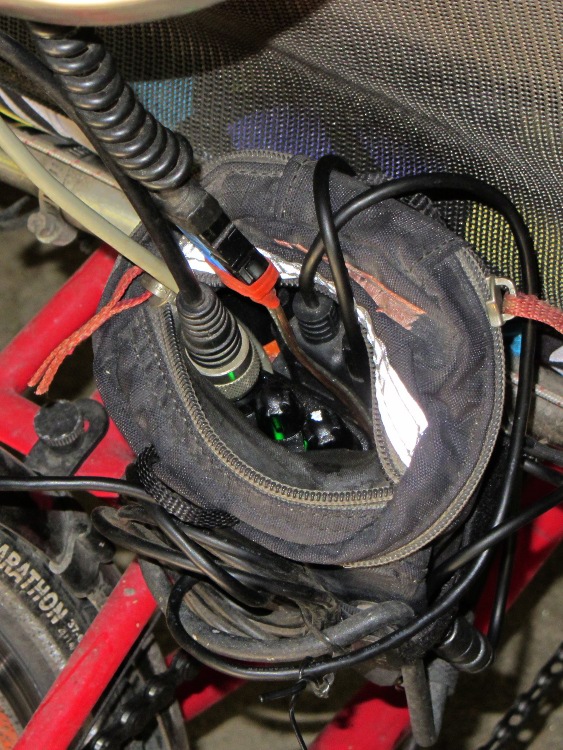
    The bag on my bike hasn’t accumulated quite so much crud, because it’s only a few months old, but it’s just as crowded:

    KG-UV3D + GPS interface on Tour Easy - top view
    KG-UV3D + GPS interface on Tour Easy – top view

    This whole “bicycle mobile APRS system”, to abuse a term, slowly grew from a voice-only interface for our ICOM IC-Z1A radios. Improving (and replacing!) one piece at a time occasionally produced horrible compatibility problems, while showing why commercial solutions justify owning metalworking tools, PCB design software, and a 3D printer.

    I long ago lost track of the number of Quality Shop Time hours devoted to all this, which may be the whole point…

    In other news, the 3D-printed fairing mountsblinky light mounts, and helmet mirror mounts continue to work fine; I’m absurdly proud of the mirrors. Mary likes her colorful homebrew seat cover that replaced a worn-out black OEM cover for a minute fraction of the price.

  • Longboard Speed-Sensing Ground Effect Lighting

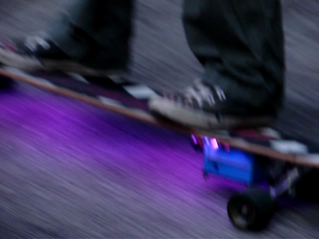
    After our Larval Engineer tweaked the code to track the maximum speed for the current run, so that the color always hits pure blue at top speed and red near standstill, we can prove it happened: we have a video! It’s much less awful than the First Light video, but with plenty of cinéma-vérité camera shake, lousy focus, and bloopers:

    Longboard In Action
    Longboard In Action

    That’s a frame extracted from one of the raw videos files using ffmpegthumbnailer:

    for t in `seq 0 10 100` ; do ffmpegthumbnailer -i mov07117.mpg -o Longboard-$t.jpg -t $t% -q 10 -s 640 ; done
    

    This view of the 3D printed case shows the power switch and the Hall effect sensor cable snaking out of the truck just below the near axle:

    Longboard RGB LED Electronics - right front view
    Longboard RGB LED Electronics – right front view

    She filled the case corners that pulled up from the build platform with a thin layer of epoxy, getting a plane surface by curing it atop waxed paper on the shop’s surface plate, to keep the polycarbonate sheet flat. I didn’t have any acorn nuts to top those nylon lock nuts, alas.

    The 4-cell Li-ion battery lives in the slice between the white aluminum plates, where it takes about four hours to charge from 3.0 V/cell. The Arduino Pro Mini lives behind the smoked polycarb sheet, where its red LED adds a mysterious touch. Maybe, some day, she’ll show the 1/rev pulse on the standard Arduino LED for debugging.

    A view from the other side shows the hole for the charger above the circuit board, with the Hall sensor out of sight below the far axle:

    Longboard RGB LED Electronics - left front view
    Longboard RGB LED Electronics – left front view

    Yes, the cable to the LEDs deserves better care. She learned that you must provide strain relief at cable-to-component junctions, which we achieved by pasting the wires to the board beside the LED strip with double-stick tape. The rest of the LED strip interconnections live atop similar tape strips. There’s nothing much protecting the LEDs or their delicate SMD resistors, but it works!

    Actually, one red LED in an RGB package went toes-up and wasn’t revived by resoldering its leads. So we jumpered around the package, subjecting the remaining two red LEDs in that string to a bit more current than they’d prefer, and that’s that.

    There’s a whole bunch not to like one could improve in both the mechanics and electronics, but it works! If you’ll grant it alpha prototype status, then I’d say it’s Good Enough; this is her project and she’ll learn a lot from how it works and how it fails, just like we all do.

    Not shown: crazy-proud father…

  • Wouxun KG-UV3D Battery Contact Locations

    Having gone to great pains to put the center of the contact studs on the GPS+voice case exactly at the center of the screws on the back of the radio:

    HT-GPS Case - Wouxun KG-UV3D rear view
    HT-GPS Case – Wouxun KG-UV3D rear view

    I now discover why Wouxun used 7 mm square pads on the batteries: the springy contacts hit the pack so far off-center from the studs that they very nearly miss the heads on the 4-40 brass screws I’m using as contacts. This family portrait shows the radio, the battery pack, and the GPS+voice case:

    Wouxun KG-UV3D - battery contact locations - GPS case
    Wouxun KG-UV3D – battery contact locations – GPS case

    The lines on the masking tape highlight where the spring contacts touch the case and barely kiss the screw heads:

    KG-UV3D contact marks on GPS case
    KG-UV3D contact marks on GPS case

    Squinting at the marks on the battery case contacts (you can’t see it in the pictures), the contact line is maybe 2.5 mm beyond the centerline of the square pads. How this worked on the first case I built, I have no clue. For this version, I deliberately filed the heads a bit less and recessed them into the case a bit more; obviously, that was the wrong thing to do, as the connection was intermittent at best.

    For the purposes of getting things working, I wrapped snippets of copper mesh tape (from NASA, according to the surplus blurb, with conductive adhesive) around thin chunks of conductive foam, then put them over the studs. The scars in the plastic came from an abortive attempt to get the springs far enough into the case surface to kiss the very edge of the studs:

    Copper mesh on GPS case contacts
    Copper mesh on GPS case contacts

    There’s no point in having a contact patch on the near side of the radio springs, because nothing ever touches there. So the right thing to do is simply move the contact studs to the far side by 3 mm, centering them around the actual contact point. That means changing the PCB layout by the same amount. That’s easy enough to do, but … drat!

    When I took the case apart to boost the mic gain, I replaced those neatly filed studs with unfiled pan head 4-40 brass screws from the same parts stock. The heads were tall enough to touch the radio spring contacts closer to their centers and make perfect contact. Not elegant, but better than that copper braid tape.

    The one thing I do not like about the Wouxun battery packs: the radio contact pads are flush with the pack surface, so there’s absolutely no protection against casual shorts when the pack isn’t on the radio. The packs also sport four bare round contacts on their outer surface that mate with the charger, two of which make direct contact with the battery; those sit inside a shallow molded recess that helps prevent inadvertent shorts.

    assume there’s a protective circuit inside the pack that turns off the current on a dead short, but I am most assuredly not going to test that assumption. When the packs aren’t on the radio (which they never will be, effective immediately), they sport a strip of tape across those radio contact pads.

  • Longboard Lighting Case: Final Edition

    After our Larval Engineer allowed as how OpenSCAD’s learning curve was rather too steep, I punched a few holes in the solid model of the case for the Longboard Ground Effect Lighting controller:

    Longboard Case Solid Model - with holes
    Longboard Case Solid Model – with holes

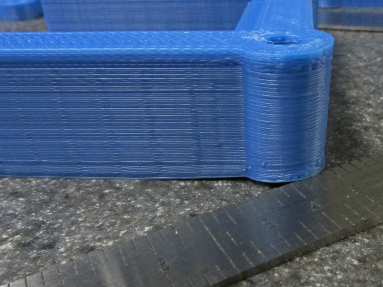
    Those rounded corners sucked the Kapton tape right off the build platform as the massive shape shrank. The top layer was the worst offender, with 1.4 mm of clearance (shown with that tapered scale) under one corner:

    Longboard case - warped corner
    Longboard case – warped corner

    The warping doesn’t matter much, because the case will be compression-loaded by screws and wave washers in the corners. We may need to fill or level the warp to keep the polycarbonate cover flat, though.

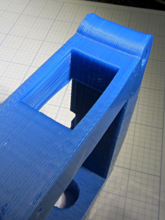
    I thought about putting a support structure in the rectangular power switch opening, then decided to just try it and see what happens. It turned out fine; this view looks up toward the as-printed top of the opening (the camera’s barrel distortion makes the curve on the bottom surface look worse than it is):

    Longboard case - switch hole overhang
    Longboard case – switch hole overhang

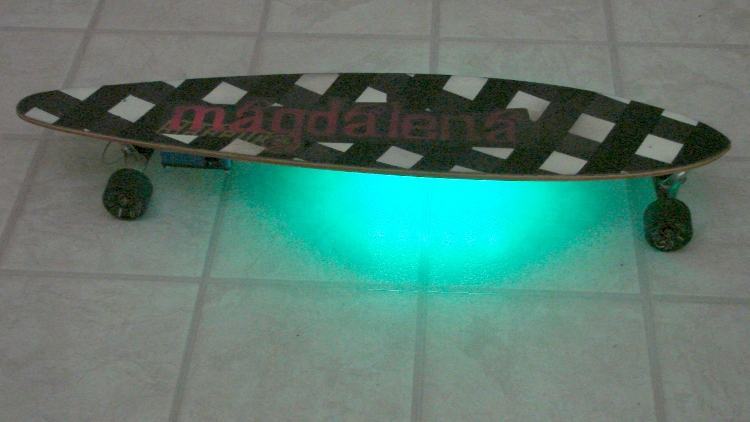
    Four stacked lithium cells produce upwards of 14.8 V, considerably more than those poor 12 V LED strips prefer to see, so I had her take some current vs. voltage data. She figured out how to convert 10-bit ADC values into battery voltage, after which she could, if she wanted to, beat her Arduino sketch into limiting the maximum PWM duty cycle to hold the LED power dissipation down to a reasonable number. Right now, it’s set to a fixed 25% and is way bright.

    Longboard with variable RGB LED Ground Effect lighting
    Longboard with variable RGB LED Ground Effect lighting

    A truly crappy First Light video taken in the driveway is there. She’s been doing the Happy Dance all day… and promises to document the whole project in gruesome detail.

    The OpenSCAD source code:

    // Longboard Ground Effect Lighting Controller Case
    // Ed Nisley KE4ZNU
    // Karen Nisley KC2SYU
    // August 2012
    
    // Layout options
    
    Layout = "Build3";
    					// Overall layout: Fit Show
    					// Printing plates: Build1 .. Buildn (see bottom!)
    					// Parts: BatteryLayer PCBLayer1 PCBLayer2
    					// Shapes: CaseShell PCBEnvelope
    
    ShowGap = 5;		// spacing between parts in Show layout
    
    //-----
    // Extrusion parameters must match reality!
    
    ThreadThick = 0.25;
    ThreadWidth = 2.0 * ThreadThick;
    
    HoleWindage = 0.2;
    
    //-- Handy stuff
    
    function IntegerMultiple(Size,Unit) = Unit * ceil(Size / Unit);
    
    Protrusion = 0.1;			// make holes end cleanly
    
    inch = 25.4;
    
    Tap10_32 = 0.159 * inch;
    Clear10_32 = 0.190 * inch;
    Head10_32 = 0.373 * inch;
    Head10_32Thick = 0.110 * inch;
    Nut10_32Dia = 0.433 * inch;
    Nut10_32Thick = 0.130 * inch;
    Washer10_32OD = 0.381 * inch;
    Washer10_32ID = 0.204 * inch;
    
    //----------------------
    // Dimensions
    
    CellWidth = 50.0;						// Lithium-ion cell dimensions
    CellLength = 60.0;
    CellThick = 6.0;
    CellClearance = 1.5;					// on all sides
    CellTabClearance = 15.0;				// for connections
    
    CellHoldWidth = 6.0;					// edge to tabs
    CellHoldLength = 4*ThreadWidth;
    
    CellCount = 4;						// cells in the battery
    
    BatteryHeight = CellCount*CellThick + 2*CellClearance;
    BatteryLength = CellLength + 2*CellClearance;
    BatteryWidth = CellWidth + 2*CellClearance;
    
    PCMWidth = 16.0;						// Battery protection module
    PCMLength = 51.0;
    PCMThick = 4.0;							// at terminal end of cells
    
    PillarOD = Washer10_32OD + 2*1.0;		// screw pillar diameter
    PillarOffset = (PillarOD/2) / sqrt(2.0);	// distance to case inside corner
    
    WallThick = 7.5;						// case wall thickness
    
    PinOD = 1.4;							// alignment pin size
    
    CaseInsideLength = BatteryLength + CellTabClearance + PCMThick;
    CaseOALength = CaseInsideLength + 2*WallThick;
    echo("Box Length outside: ",CaseOALength);
    echo("            inside: ",CaseInsideLength);
    
    WiringLength = CaseInsideLength - CellLength - CellHoldLength - PCMThick;	// wiring space at PCM
    echo("Wiring length: ",WiringLength);
    
    CaseInsideWidth = BatteryWidth;
    CaseOAWidth = CaseInsideWidth + 2*WallThick;
    echo("Box Width outside: ",CaseOAWidth);
    echo("           inside: ",CaseInsideWidth);
    echo("Screw OC length: ",CaseInsideLength + 2*PillarOffset);
    echo("          width: ",CaseInsideWidth + 2*PillarOffset);
    
    PCBThick = 2.0;							// PCB thickness
    PCBMargin = 3.0;						// clamping margin around PCB edge
    PartHeight = 17.0;						// height of components above PCB (mind the switch!)
    WiringThick = 5.0;						// wiring below PCB
    
    echo("PCB thickness:",PCBThick);
    echo("    clamp margin: ",PCBMargin);
    echo("    wiring: ",WiringThick);
    echo("    components: ",PartHeight);
    
    PCBLayer1Thick = IntegerMultiple(WiringThick + PCBThick/2,ThreadThick);
    PCBLayer2Thick = IntegerMultiple(PartHeight + PCBThick/2,ThreadThick);
    
    echo("Battery compartment height: ",BatteryHeight);
    echo("PCB Layer 1 height: ",PCBLayer1Thick);
    echo("PCB Layer 2 height: ",PCBLayer2Thick);
    
    PlateThick = 1/16 * inch;				// aluminum mount / armor plates
    
    echo("Total height: ",2*PlateThick + BatteryHeight + PCBLayer1Thick + PCBLayer2Thick);
    
    ChargePlugOD = 11.5;					// battery charger plug
    ChargeJackHeightOC = 6.5;				// coaxial jack center pin height from PCB
    
    SwitchLength = 20.0;					// master power switch
    SwitchWidth = 13.0;
    
    WheelCableOD = 3.0;						// 3-conductor from wheel rotation sensor
    
    LEDCableWidth = 10.0;					// 6 conductor loose wires to LED strips
    LEDCableThick = 2.0;
    
    //----------------------
    // Useful routines
    
    module PolyCyl(Dia,Height,ForceSides=0) {			// based on nophead's polyholes
    
      Sides = (ForceSides != 0) ? ForceSides : (ceil(Dia) + 2);
    
      FixDia = Dia / cos(180/Sides);
    
      cylinder(r=(FixDia + HoleWindage)/2,
               h=Height,
    	   $fn=Sides);
    }
    
    module ShowPegGrid(Space = 10.0,Size = 1.0) {
    
      Range = floor(50 / Space);
    
    	for (x=[-Range:Range])
    	  for (y=[-Range:Range])
    		translate([x*Space,y*Space,Size/2])
    		  %cube(Size,center=true);
    
    }
    
    //-------------------
    // Shapes
    
    module CaseShell(h=1.0) {
    
      difference() {
    	union() {
    	  translate([0,0,h/2])
    		cube([CaseOALength,CaseOAWidth,h],center=true);
    
    	  for (x=[-1,1])
    		for (y=[-1,1])
    		  translate([x*(PillarOffset + CaseInsideLength/2),
    					y*(PillarOffset + CaseInsideWidth/2),
    					h/2])
    			cylinder(r=PillarOD/2,h,center=true,$fn=4*6);
    	}
    
    	for (x=[-1,1])					// screw holes on corners
    	  for (y=[-1,1])
    		translate([x*(PillarOffset + CaseInsideLength/2),
    				  y*(PillarOffset + CaseInsideWidth/2),
    				  -Protrusion])
    		  PolyCyl(Clear10_32,(h + 2*Protrusion),8);
    
    	for (x=[-1,1])					// alignment pins in width walls
    	  translate([x*(CaseOALength - WallThick)/2,0,-Protrusion])
    	  rotate(45)
    		  PolyCyl(PinOD,(h + 2*Protrusion));
    	for (y=[-1,1])					// alignment pins in length walls
    	  translate([0,y*(CaseOAWidth - WallThick)/2,-Protrusion])
    	  rotate(45)
    		  PolyCyl(PinOD,(h + 2*Protrusion));
    
      }
    }
    
    module BatteryLayer() {
    
      difference() {
    	CaseShell(BatteryHeight);
    
        translate([0,0,BatteryHeight/2]) {
    	  union() {
    		translate([-(CaseInsideLength/2 - BatteryLength/2),0,0])
    		  cube([BatteryLength,
    			   BatteryWidth,
    			   BatteryHeight + 2*Protrusion],
    			   center=true);
    		cube([CaseInsideLength,
    			 (BatteryWidth - 2*CellHoldWidth),
    			 BatteryHeight + 2*Protrusion],
    			 center = true);
    		translate([(CaseInsideLength/2 - WiringLength/2),0,0])
    		  cube([WiringLength,
    				max(BatteryWidth,PCMLength),
    				BatteryHeight + 2*Protrusion],
    				  center=true);
    	  }
    	}
      }
    }
    
    module PCBEnvelope() {
    
      union() {
    	translate([0,0,WiringThick + PCBThick + PartHeight/2])
    	  cube([CaseInsideLength - 2*PCBMargin,
    		   CaseInsideWidth - 2*PCBMargin,
    		   PartHeight + 2*Protrusion],
    		   center=true);
    
    	translate([0,0,WiringThick + PCBThick/2])
    	  cube([CaseInsideLength,CaseInsideWidth,PCBThick],center=true);
    
    	translate([0,0,WiringThick/2])
    	  cube([CaseInsideLength - 2*PCBMargin,
    		   CaseInsideWidth - 2*PCBMargin,
    		   WiringThick + 2*Protrusion],
    		   center=true);
      }
    }
    
    module PCBLayer1() {
    
      difference() {
    	CaseShell(PCBLayer1Thick);
    	PCBEnvelope();
      }
    
    }
    
    module PCBLayer2() {
    
      difference() {
    	CaseShell(PCBLayer2Thick);
    	translate([0,0,-(WiringThick + PCBThick/2)])
    	  PCBEnvelope();
    	translate([25,0,(PCBThick/2 + ChargeJackHeightOC)])
    	  rotate([90,0,0])
    		PolyCyl(ChargePlugOD,CaseOAWidth);
    	translate([25,CaseOAWidth/2,PCBLayer2Thick/2])
    	  rotate([90,0,0])
    		cube([SwitchLength,SwitchWidth,CaseOAWidth],center=true);
    	translate([-CaseOALength/2,0,PCBThick/2])
    	  rotate([0,-90,0])
    		cube([2*WheelCableOD,WheelCableOD,CaseOALength],center=true);
    	translate([CaseOALength/2,0,PCBThick/2])
    	  rotate([90,0,90])
    		cube([LEDCableWidth,2*LEDCableThick,CaseOALength],center=true);
      }
    
    }
    
    module Aluminum() {
      translate([0,0,PlateThick/2])
    	cube([1.1*CaseOALength,1.1*CaseOAWidth,PlateThick - Protrusion],center=true);
    }
    
    //-------------------
    // Build things...
    
    ShowPegGrid();
    
    if ("Battery" == Layout)
      Battery();
    
    //if ("CaseShell" == Layout)
    //  CaseShell(something here!!!);
    
    if ("BatteryLayer" == Layout)
      BatteryLayer();
    
    if ("PCBEnvelope" == Layout)
      PCBEnvelope();
    
    if ("PCBLayer1" == Layout)
      PCBLayer1();
    
    if ("PCBLayer2" == Layout)
      PCBLayer2();
    
    if ("Fit" == Layout) {
      color("LightBlue") BatteryLayer();
      translate([0,0,BatteryHeight + PlateThick])
    	color("Green") PCBLayer1();
      translate([0,0,BatteryHeight + PlateThick + PCBLayer1Thick])
    	color("Cyan") PCBLayer2();
    }
    
    if ("Show" == Layout) {
      color("LightBlue") BatteryLayer();
      translate([0,0,BatteryHeight + PlateThick + ShowGap])
    	color("Green") PCBLayer1();
      translate([0,0,BatteryHeight + PlateThick + PCBLayer1Thick + 2*ShowGap])
    	color("Cyan") PCBLayer2();
    }
    
    if ("Build1" == Layout)
      rotate(90) BatteryLayer();
    
    if ("Build2" == Layout)
      rotate(90) PCBLayer1();
    
    if ("Build3" == Layout)
      translate([0,0,PCBLayer2Thick])
    	rotate([0,180,90])
    	  PCBLayer2();
    
    
  • TinyTrak3+ Trimpots: Not All Are Created Equal

    I designed the GPS+Audio case around the TinyTrak3+ board in my radio, which has two square, blue-plastic trimpots. The case worked fine for that board. Then I printed the case for the next bike and that TT3+ didn’t slide neatly into place:

    TinyTrak3+ trimpot overhang
    TinyTrak3+ trimpot overhang

    Turns out that one of the three TT3+ boards uses plastic trimpots and the other two have metal trimpots bent to fit the existing holes (so they’re not a drop-in replacement), with a very slight overhang beyond the edge of the PCB.

    So I attacked the case with some riffler files and carved a notch above the PCB slot. No pictures of that, lest you think I’m a butcher of lovely 3D printed objects. Next time: build the notch into the case’s solid model.

    Most likely, this is the only instance of those pots causing anyone a problem…

  • Longboard Ground Effect Lighting Case

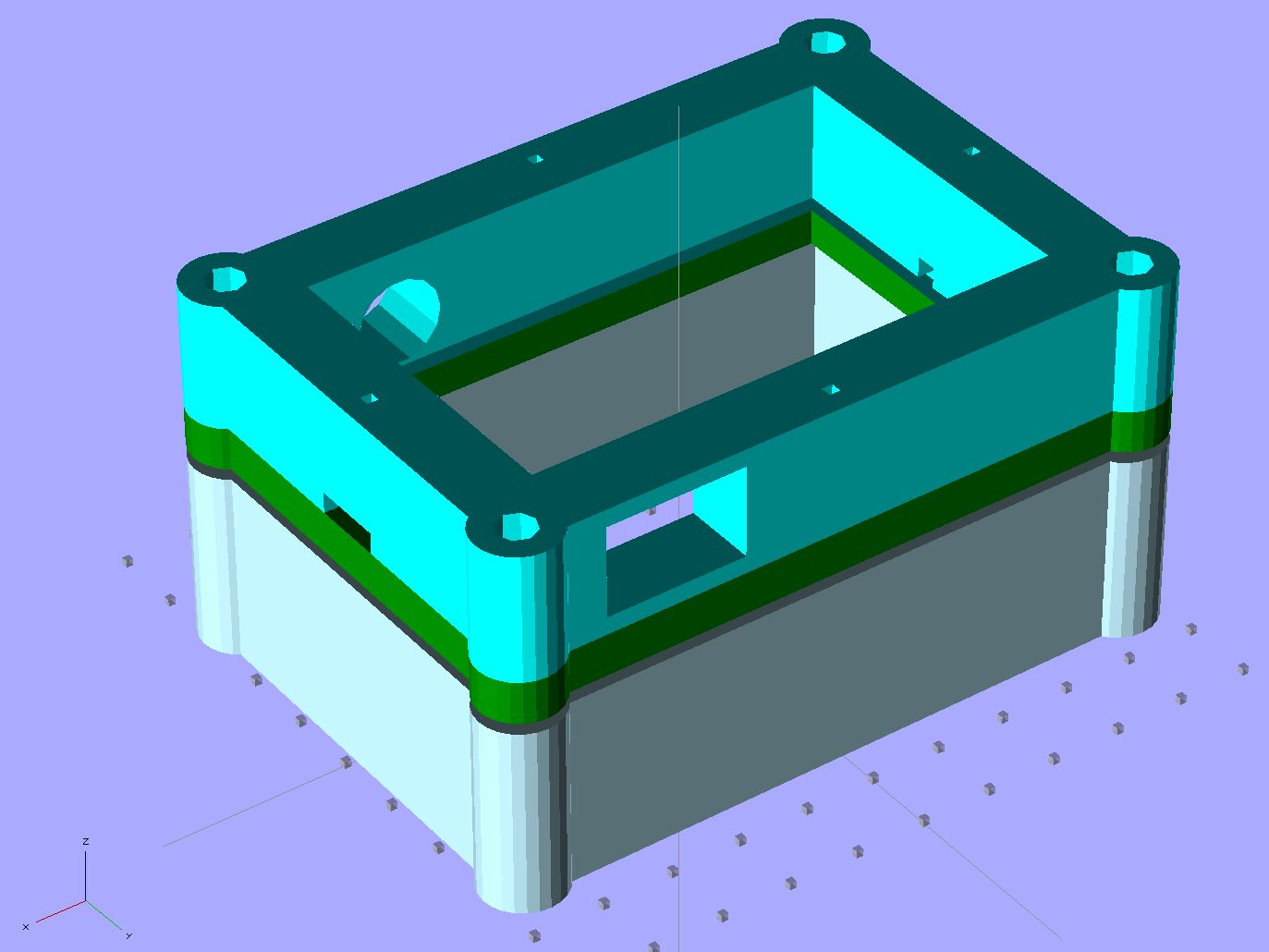
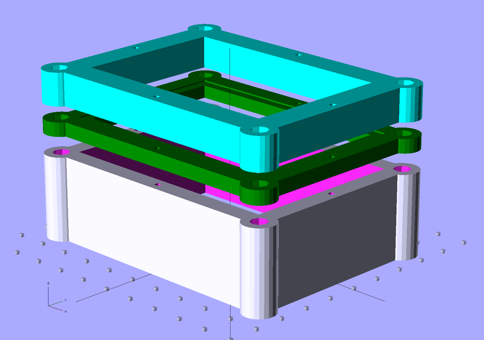
    Our Larval Engineer has been diligently procrastinating on her summer project to add ground effect lighting to her longboard. I’m hereby depriving her of the opportunity to learn enough OpenSCAD to build a case from scratch:

    Longboard Ground Effect Lighting Case - exploded view
    Longboard Ground Effect Lighting Case – exploded view

    This is upside-down from its in-use position, but she’ll have it in this orientation on the bench. Four 10-32 screws clamp the whole affair together and hold it to a bottom aluminum plate with threads to suit; that plate also gets bolted between the longboard and the rear truck.

    The general idea is that four 2 A·h lithium prismatic cells live in the bottom slice with their protection circuit, sandwiched between two aluminum plates that should protect them from all but catastrophic impact. The circuit board (which ought to be a PCB, but we’ll go with hand wiring for the first iteration) gets clamped in the recess between the two upper slices, above the upper aluminum plate. A polycarbonate sheet on top provides visibility for the Arduino blinky LED inside and shows off the circuitry to one and all.

    I think a ridge on each long wall should suffice to hold the cells against the end wall; we don’t have the cells in hand to figure that out yet. She gets to add internal partitions, cable cutouts, and suchlike.

    Oh. “Ground effect lighting” means ten RGB LED strips glued under the longboard deck. Her innovation is to make the LED color depend on the speed, which can range upward to scary-fast. It’s a simple matter of software, using a Hall effect sensor for input. This will look much better after dark, but she’s pretty much nocturnal anyway.
    The OpenSCAD source code:

    // Longboard Ground Effect Lighting Controller Case
    // Ed Nisley KE4ZNU
    // Karen Nisley KC2SYU
    // July 2012
    
    // Layout options
    
    Layout = "Show";
     // Overall layout: Fit Show
     // Printing plates: Build1 .. Buildn (see bottom!)
     // Parts: BatteryLayer PCBLayer1 PCBLayer2
     // Shapes: CaseShell PCBEnvelope
    
    ShowGap = 5; // spacing between parts in Show layout
    
    //-----
    // Extrusion parameters must match reality!
    
    ThreadThick = 0.25;
    ThreadWidth = 2.0 * ThreadThick;
    
    HoleWindage = 0.2;
    
    //-- Handy stuff
    
    function IntegerMultiple(Size,Unit) = Unit * ceil(Size / Unit);
    
    Protrusion = 0.1; // make holes end cleanly
    
    inch = 25.4;
    
    Tap10_32 = 0.159 * inch;
    Clear10_32 = 0.190 * inch;
    Head10_32 = 0.373 * inch;
    Head10_32Thick = 0.110 * inch;
    Nut10_32Dia = 0.433 * inch;
    Nut10_32Thick = 0.130 * inch;
    Washer10_32OD = 0.381 * inch;
    Washer10_32ID = 0.204 * inch;
    
    //----------------------
    // Dimensions
    
    CellWidth = 50.0; // Lithium-ion cell dimensions
    CellLength = 60.0;
    CellThick = 6.0;
    CellClearance = 1.5; // on all sides
    CellTabClearance = 10.0; // for connections
    
    BatteryCount = 4; // cells in the battery
    BatteryHeight = BatteryCount*CellThick + 2*CellClearance;
    
    PCMWidth = 16.0; // Battery protection board
    PCMLength = 50.0;
    PCMThick = 4.0; // at terminal end of cells
    
    PillarOD = Washer10_32OD + 2*0.5; // screw pillar diameter
    PillarOffset = (PillarOD/2) / sqrt(2.0); // distance to case inside corner
    
    WallThick = 6.0; // case wall thickness
    
    PinOD = 1.4; // alignment pin size
    
    CaseOALength = CellLength + CellClearance + CellTabClearance + PCMThick + 2*WallThick;
    CaseInsideLength = CaseOALength - 2*WallThick;
    echo("Box Length outside: ",CaseOALength);
    echo(" inside: ",CaseInsideLength);
    
    CaseOAWidth = CellWidth + 2*CellClearance + 2*WallThick;
    CaseInsideWidth = CaseOAWidth - 2*WallThick;
    echo("Box Width outside: ",CaseOAWidth);
    echo(" inside: ",CaseInsideWidth);
    
    CaseOAHeight = BatteryCount * CellThick + CellClearance;
    
    PCBThick = 1.0; // PCB thickness
    PCBMargin = 3.0; // clamping margin around PCB edge
    PartHeight = 10.0; // height of components above PCB
    WiringThick = 4.0; // wiring below PCB
    
    echo("PCB thickness:",PCBThick);
    echo(" clamp margin: ",PCBMargin);
    echo(" wiring: ",WiringThick);
    echo(" components: ",PartHeight);
    
    PCBLayer1Thick = IntegerMultiple(WiringThick + PCBThick/2,ThreadThick);
    PCBLayer2Thick = IntegerMultiple(PartHeight + PCBThick/2,ThreadThick);
    
    echo("Battery compartment height: ",BatteryHeight);
    echo("PCB Layer 1 height: ",PCBLayer1Thick);
    echo("PCB Layer 2 height: ",PCBLayer2Thick);
    
    PlateThick = 1/16 * inch; // aluminum mount / armor plates
    
    echo("Total height: ",2*PlateThick + BatteryHeight + PCBLayer1Thick + PCBLayer2Thick);
    
    //----------------------
    // Useful routines
    
    module PolyCyl(Dia,Height,ForceSides=0) { // based on nophead's polyholes
    
    Sides = (ForceSides != 0) ? ForceSides : (ceil(Dia) + 2);
    
    FixDia = Dia / cos(180/Sides);
    
    cylinder(r=(FixDia + HoleWindage)/2,
     h=Height,
     $fn=Sides);
    }
    
    module ShowPegGrid(Space = 10.0,Size = 1.0) {
    
    Range = floor(50 / Space);
    
    for (x=[-Range:Range])
     for (y=[-Range:Range])
     translate([x*Space,y*Space,Size/2])
     %cube(Size,center=true);
    
    }
    //-------------------
    // Shapes
    
    module CaseShell(h=1.0) {
    
    difference() {
     union() {
     translate([0,0,h/2])
     cube([CaseOALength,CaseOAWidth,h],center=true);
    
    for (x=[-1,1])
     for (y=[-1,1])
     translate([x*(PillarOffset + CaseInsideLength/2),
     y*(PillarOffset + CaseInsideWidth/2),
     h/2])
     cylinder(r=PillarOD/2,h,center=true,$fn=4*6);
     }
    
    for (x=[-1,1]) // screw holes on corners
     for (y=[-1,1])
     translate([x*(PillarOffset + CaseInsideLength/2),
     y*(PillarOffset + CaseInsideWidth/2),
     -Protrusion])
     PolyCyl(Clear10_32,(h + 2*Protrusion),8);
    
    for (x=[-1,1]) // alignment pins in width walls
     translate([x*(CaseOALength - WallThick)/2,0,-Protrusion])
     rotate(45)
     PolyCyl(PinOD,(h + 2*Protrusion));
     for (y=[-1,1]) // alignment pins in length walls
     translate([0,y*(CaseOAWidth - WallThick)/2,-Protrusion])
     rotate(45)
     PolyCyl(PinOD,(h + 2*Protrusion));
    
    }
    }
    
    module BatteryLayer() {
    
    difference() {
     CaseShell(BatteryHeight);
    
    translate([0,0,BatteryHeight/2])
     cube([CaseOALength - 2*WallThick,
     CaseOAWidth - 2*WallThick,
     BatteryHeight + 2*Protrusion],
     center=true);
     }
    }
    
    module PCBEnvelope() {
    
    union() {
     translate([0,0,WiringThick + PCBThick + PartHeight/2])
     cube([CaseInsideLength - 2*PCBMargin,
     CaseInsideWidth - 2*PCBMargin,
     PartHeight + 2*Protrusion],
     center=true);
    
    translate([0,0,WiringThick + PCBThick/2])
     cube([CaseInsideLength,CaseInsideWidth,PCBThick],center=true);
    
    translate([0,0,WiringThick/2])
     cube([CaseInsideLength - 2*PCBMargin,
     CaseInsideWidth - 2*PCBMargin,
     WiringThick + 2*Protrusion],
     center=true);
     }
    }
    
    module PCBLayer1() {
    
    difference() {
     CaseShell(PCBLayer1Thick);
     PCBEnvelope();
     }
    
    }
    
    module PCBLayer2() {
    
    difference() {
     CaseShell(PCBLayer2Thick);
     translate([0,0,-(WiringThick + PCBThick/2)])
     PCBEnvelope();
     }
    
    }
    
    module Aluminum() {
     translate([0,0,PlateThick/2])
     cube([1.1*CaseOALength,1.1*CaseOAWidth,PlateThick - Protrusion],center=true);
    }
    
    //-------------------
    // Build things...
    
    ShowPegGrid();
    
    if ("Battery" == Layout)
     Battery();
    
    if ("CaseShell" == Layout)
     CaseShell(CaseOAHeight);
    
    if ("BatteryLayer" == Layout)
     BatteryLayer();
    
    if ("PCBEnvelope" == Layout)
     PCBEnvelope();
    
    if ("PCBLayer1" == Layout)
     PCBLayer1();
    
    if ("PCBLayer2" == Layout)
     PCBLayer2();
    
    if ("Fit" == Layout) {
     BatteryLayer();
     translate([0,0,BatteryHeight + PlateThick])
     color("Green") PCBLayer1();
     translate([0,0,BatteryHeight + PlateThick + PCBLayer1Thick])
     color("Cyan") PCBLayer2();
    }
    
    if ("Show" == Layout) {
     BatteryLayer();
     translate([0,0,BatteryHeight + PlateThick + ShowGap])
     color("Green") PCBLayer1();
     translate([0,0,BatteryHeight + PlateThick + PCBLayer1Thick + 2*ShowGap])
     color("Cyan") PCBLayer2();
    }
    
    if ("Build1" == Layout)
     rotate(90) BatteryLayer();
    
    if ("Build2" == Layout)
     rotate(90) PCBLayer1();
    
    if ("Build3" == Layout)
     translate([0,0,PCBLayer2Thick])
     rotate([0,180,90])
     PCBLayer2();