The Smell of Molten Projects in the Morning

Ed Nisley's Blog: Shop notes, electronics, firmware, machinery, 3D printing, laser cuttery, and curiosities. Contents: 100% human thinking, 0% AI slop.

Tag: Thing-O-Matic

Using and tweaking a Makerbot Thing-O-Matic 3D printer

  • Wouxun KG-UV3D Plug Plate

    Based on those measurements that suggest spacing the plugs at 11.5 mm on center, I tweaked that parameter in the source code there and printed another one, just like the other one. Actually, I printed four of the fool things this time:

    Wouxun plug plates - 11.5 mm fixture
    Wouxun plug plates – 11.5 mm fixture

    With the plugs in the gluing fixture and the fixture in the vise, a ring of epoxy around the threaded sides holds them in place:

    Wouxun plug plate - wired
    Wouxun plug plate – wired

    A trial fit in the Wouxun KG-UV3D shows that the jacks prefer the 11.2 mm spacing I measured on the Wouxun headset, but they’ll accept plugs on 11.5 mm centers. I don’t know if that’s a real specification difference, a manufacturing tolerance, or what.

    FWIW, I’ve been using snippets of that cable forever, because it’s perfect for this application: two unshielded conductors and three more inside a braid, supple as a snake. It’s surplus, of course, with a gorgeous push-lock plug (and the jack!) on one end that must have cost a fortune… and which I’ll never to use for anything. Got two of them, just in case.

    Mushing an epoxy putty turd on the top anchors everything in place and protects the wires:
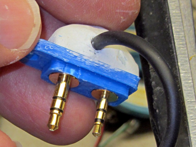
    Wouxun plug plate - epoxy cap
    Wouxun plug plate – epoxy cap

    In point of fact, the cable insulation isn’t anchored inside the blob and a minor tug could pull it loose. There will be a bit of slack at the case to allow for unlatching it from the radio, but the lashup will spend its entire life inside a snug pouch, so it shouldn’t come to any harm. We shall see.

  • Kenwood / Wouxun Headset Jack Spacing

    Wouxun plug mounting plate - overview
    Wouxun plug mounting plate – overview

    Try as I might, I cannot uncover a definitive answer to this simple question: What’s the center-to-center spacing of the mic and earphone jacks on the side of Kenwood and Wouxun HTs?

    The usual searches produce answers like 11 and 12 mm, both of which are obviously wrong, as can be determined eyeballometrically just by holding a scale against the plugs.

    Based on measurements I made on a Wouxun headset, the yellow plug mounting plate put the plugs on 11.2 mm centers and they fit into the KG-UV3D radio; it’s been working fine ever since.

    However, having just measured a speaker/mic and a headset, both from Kenwood, I come up with 11.5 mm. Frankly, I trust the Kenwood hardware a bit more: the plugs seem more rugged and the overall production values are higher.

    The calculation is simple: measure the pin diameters, then subtract half their sum from the outside distance across the pins. Cross-check by adding half the sum to the inside distance between the pins, which should give the same answer. It helps if the pins are actually round.

    The jacks in the Kenwood and Wouxun radios have enough compliance to accept either a Wouxun or a Kenwood headset plug without complaint. Maybe it doesn’t matter?

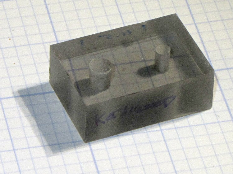
    Despite that, I made another gluing fixture with 11.5 mm spacing:

    Plug alignment plate - 11.5 mm spacing
    Plug alignment plate – 11.5 mm spacing

    Those are 0.1 inch grids; it’s a little bitty block of smoke-gray polycarbonate from the scrap heap. The plugs are nominally 3.5 mm (which is not 1/8 inch in this universe) and 2.5 mm, with clearance drills #28 and #39.

    Then I tried poking those 11.2 mm spaced plugs, now firmly epoxied in place in the yellow plate, and guess what: they don’t fit, no how no way. That’s not surprising, because there’s no compliance on either side of the joint and the plugs aren’t on the right centers for the fixture. Makes for a good No-Go gauge, I suppose.

    However, I think I’ll tweak the solid model spacing to 11.5 mm and run off another plug mounting plate for the next radio.

    FWIW, our ICOM IC-Z1A HTs use a sensible 10.0 mm spacing and that old fixture worked fine.

  • HT GPS+Voice: Battery Contacts

    For this version of the contacts (the old version is there) that make the GPS interface look like a standard Wouxun lithium battery, I left a bit more of the slot on the brass screw heads and increased the recess depth to compensate:

    HT-GPS Case - Battery contacts
    HT-GPS Case – Battery contacts

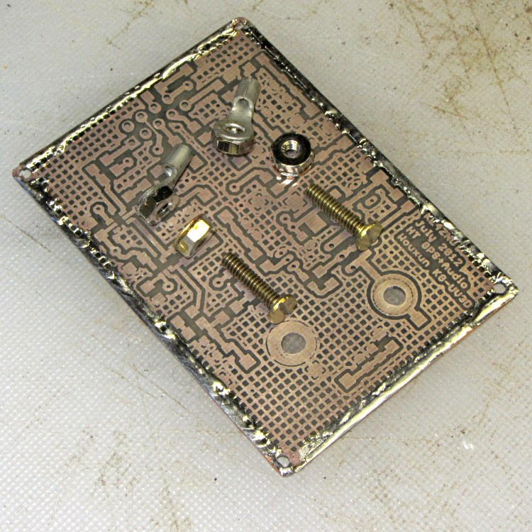
    The nuts all have fancy nickel plating, with washers & ring lugs silver-soldered in place:

    HT-GPS PCB - battery contact parts
    HT-GPS PCB – battery contact parts

    The trial fit looks OK:

    HT-GPS Case - PCB and battery contacts - end view
    HT-GPS Case – PCB and battery contacts – end view

    I even found the cutest little flat 1/4 inch wrench that fits 4-40 nuts, so I can do a better job of crunching the PCB between the nuts. That excess screw length has got to go, too…

  • HT GPS+Voice Case: Latch Bar

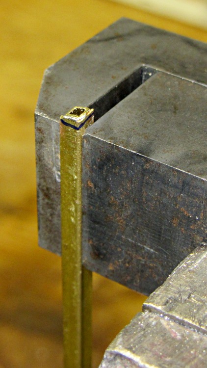
    This iteration of the case latch has slightly larger brass tubing on the ends, hand filed to match the case angle:

    Shaping case latch bar
    Shaping case latch bar

    It’s pretty much the same process described there and is why I set up that slitting saw arbor for the next time.

    The final result looks pretty good:

    HT-GPS Case - Latch plate detail
    HT-GPS Case – Latch plate detail

    Those tubing snippets really must be two different lengths: the bar slides to the right (in that picture) to release the case, so:

    • The short tube and the notch must fit into the space between the edge of the case and the release slot.
    • The long tube slides outward, with a mark to indicate when the notches align with the release slots.

    In principle, you could slide the bar until the shorter tube jams against the latch ramp on the radio, but this case (plus the end caps) turned out to be exactly as long as the distance available and is a rather snug press fit. The next version will be 0.75 mm shorter and should fit better, although snug is good in this situation.

  • Wouxun HT GPS+Voice Case: Colors!

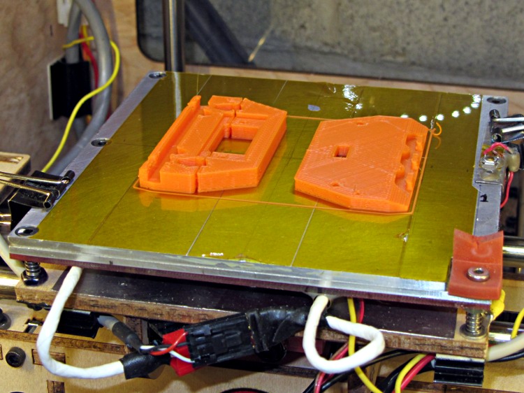
    Rather than print another green case, the new, improved case has orange end caps:

    HT-GPS Case - End caps on build plate
    HT-GPS Case – End caps on build plate

    And a blue shell that’s a bit easier on the eye:

    HT-GPS Case - Shell on build platform
    HT-GPS Case – Shell on build platform

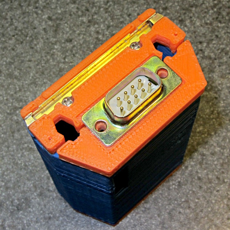
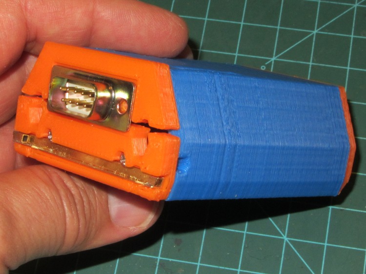
    Put ’em together and it certainly looks peppy, doesn’t it?

    HT-GPS Case - trial fit
    HT-GPS Case – trial fit

    That’s a trial fit with nothing inside, of course.

    Next step: circuitry!

  • CO2 Capsule Fins: Party Edition

    CO2 capsules with multicolored fins
    CO2 capsules with multicolored fins

    These emerged from some recent printing sessions, where they served to join two successive colors as I changed ABS filaments.

    Whenever I give a talk, these are the last tchotchkes to go. Maybe some festive party fins will help?

  • Harbor Freight Slitting Saw Arbor

    A three-pack of 100-tooth 2 inch cutoff saw blades followed me home from Harbor Freight a while ago. Although they’re intended for a craptastic HF tabletop saw, I thought they might come in handy on the Sherline for slicing lengths of brass tubing. The reviews for the saw indicate the blades are no good for steel, barely adequate for brass, and dandy for wood; they have nowhere near enough teeth for a screw cutoff blade.

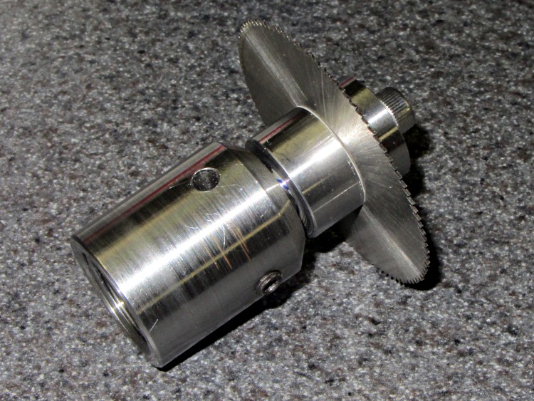
    None of the arbors in my collection fit a blade with a 3/8 inch hole, so a bit of lathe work produced one while the 3D printer cranked out a GPS+audio case:

    Cutoff saw arbor in Sherline toolholder
    Cutoff saw arbor in Sherline toolholder

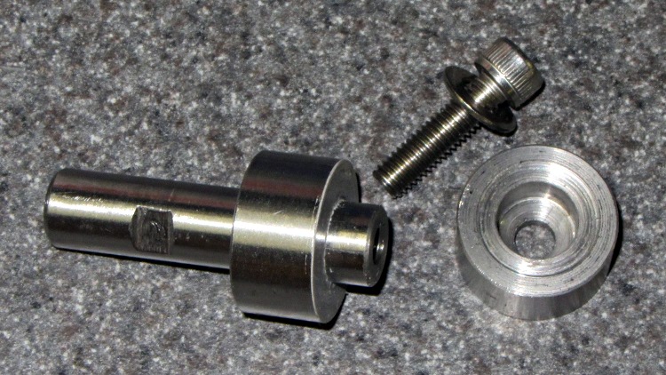
    The shaft is 3/8 inch drill rod and the collars are 3/4 inch drill rod, both of O1 oil-hardening steel that will remain forever unhardened, fitting into a Sherline endmill toolholder. I drilled-and-bored the collars to a slip fit on the shaft, then epoxied the rear one in place:

    img_2156 - Cutoff saw arbor - parts
    img_2156 – Cutoff saw arbor – parts

    I drilled a 0.6 inch deep blind hole in the shaft and tapped it 10-32 all the way down for a 1/2 inch SHCS. A bag of assorted 10-32 taps produced a bottoming tap that came in handy, but I put tapping in the same category as parallel parking: I’ll walk half a mile to not parallel park the van. Couldn’t avoid it this time.

    The flat on the shaft came from a bit of hand filing, which was easier than setting up the mill.

    The front collar’s undercut ensures just the rim contacts the blade. The photo shows the vanishingly thin layer of epoxy on the rear collar that mooshed out as I clamped the stack together:

    • Fixed (rear) collar
    • Waxed paper with a 3/8 inch hole punched in the middle
    • Cutoff blade
    • Split lockwasher for a bit of space
    • Loose (front) collar
    • Socket head cap screw

    After the epoxy cured, a pass through the lathe skimmed off that thin epoxy layer and trued up the fixed collar face to eliminate the last bit of wobble. The radial runout remains just enough so that one tooth tings before the others engage, but I’m not entirely convinced that’s due to the (minimal) shaft-to-blade clearance.

    In use, putting the split lockwasher between the loose collar and the SHCS provides a little clamping compliance.

    At some point, I’m sure this thing will come in handy…