Because the ET227 transistor operates at power line voltages through a full wave rectifier, the base drive circuit requires an optoisolator. The ET227 is a low-gain device with hFE < 10, so it takes about 100 mA of base drive to control an amp of motor current, soooo the optoisolator needs a current amplifier.
I used an MJE2955T PNP transistor, with the emitter powered from an isolated +5 V supply to let the optoisolator pull current from the base. You could use an NPN transistor as a Darlington amp, but wiring the collectors together means the driver dissipates way too much power; the PNP seemed all-around easier.
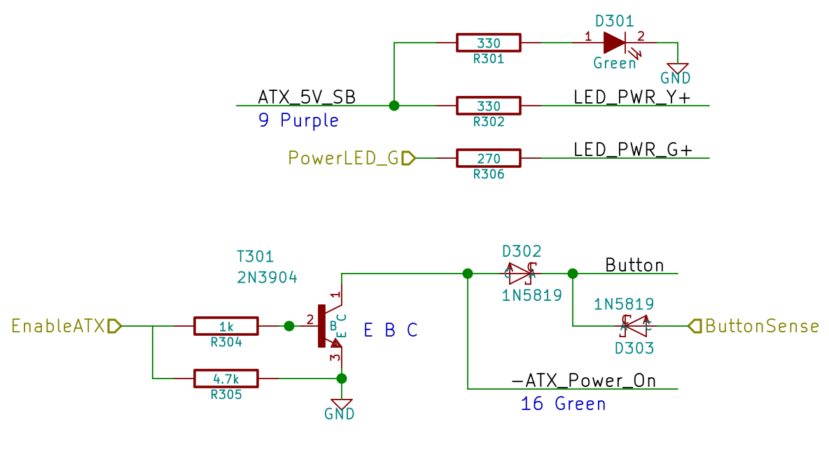
That circuitry sprawls across the middle of the schematic:
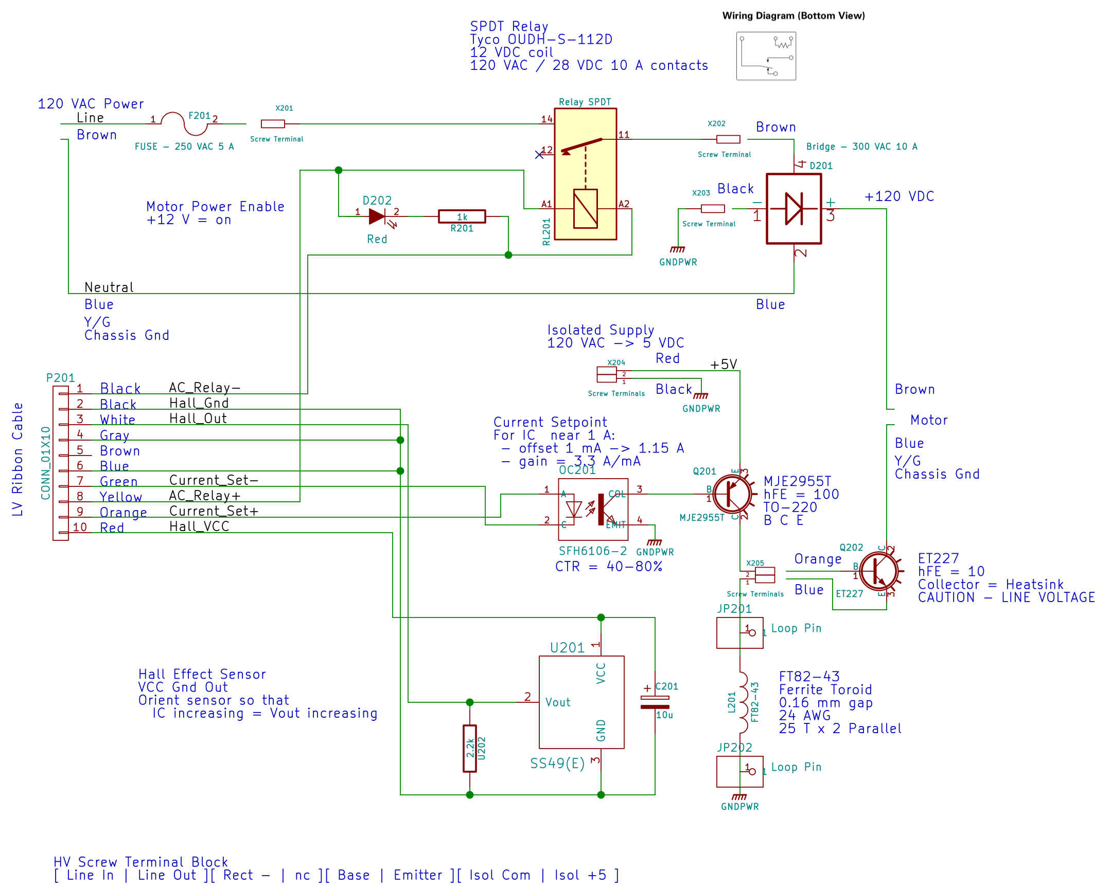
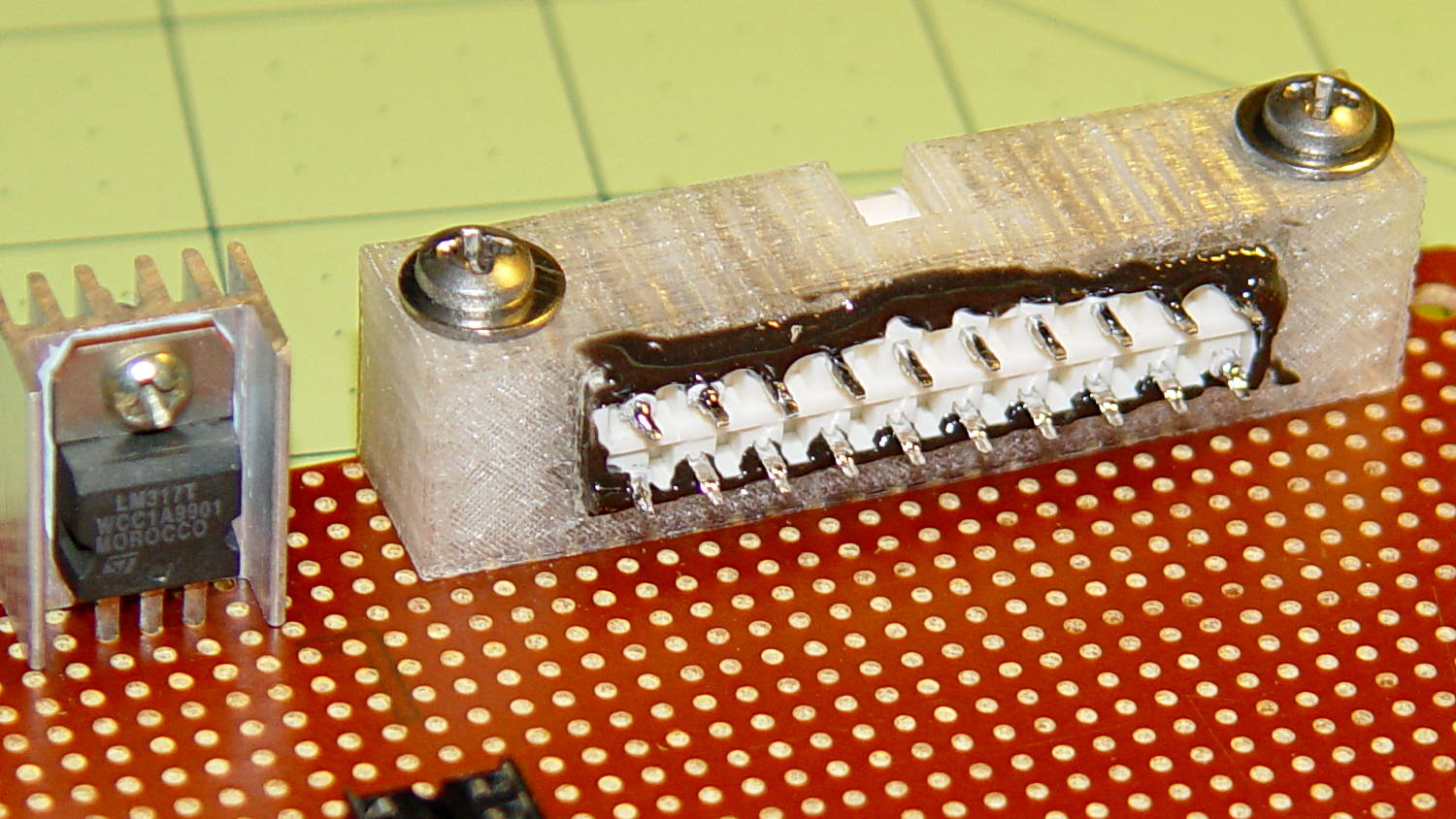
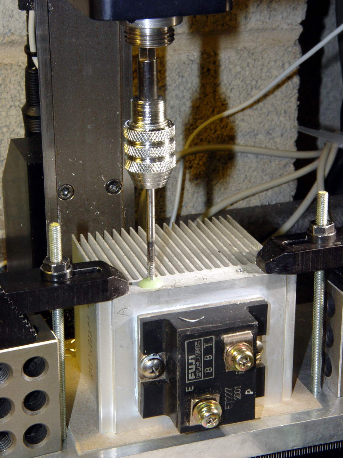
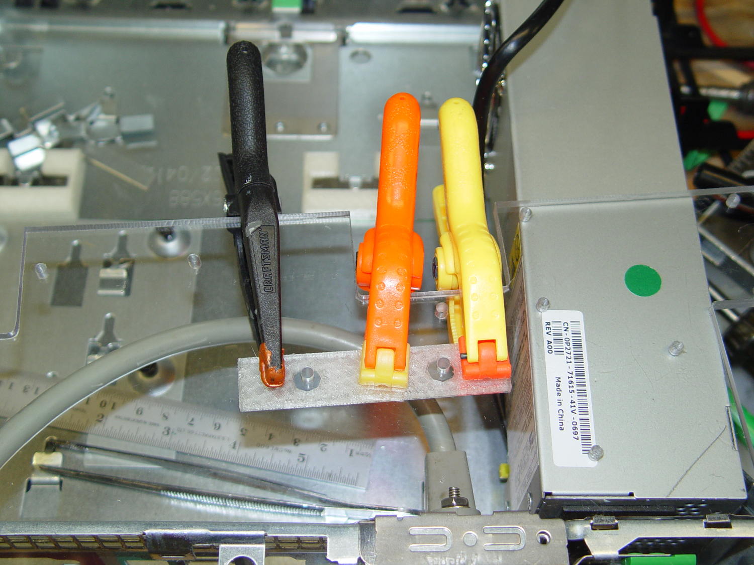
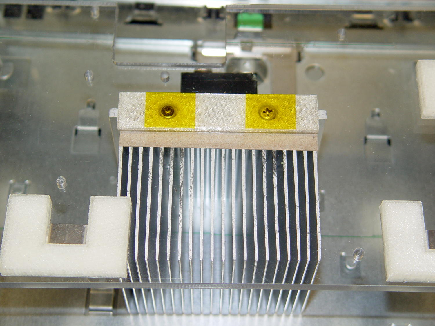
The ET227 base runs at about 900 mV, so the MJE2955 PNP transistor will dissipate half a watt and needs a little heatsink, seen over on the right (with the hulking ET227 heatsink at the edge):

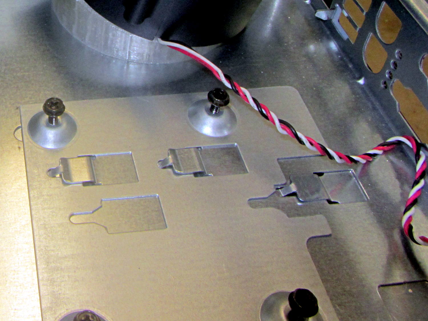
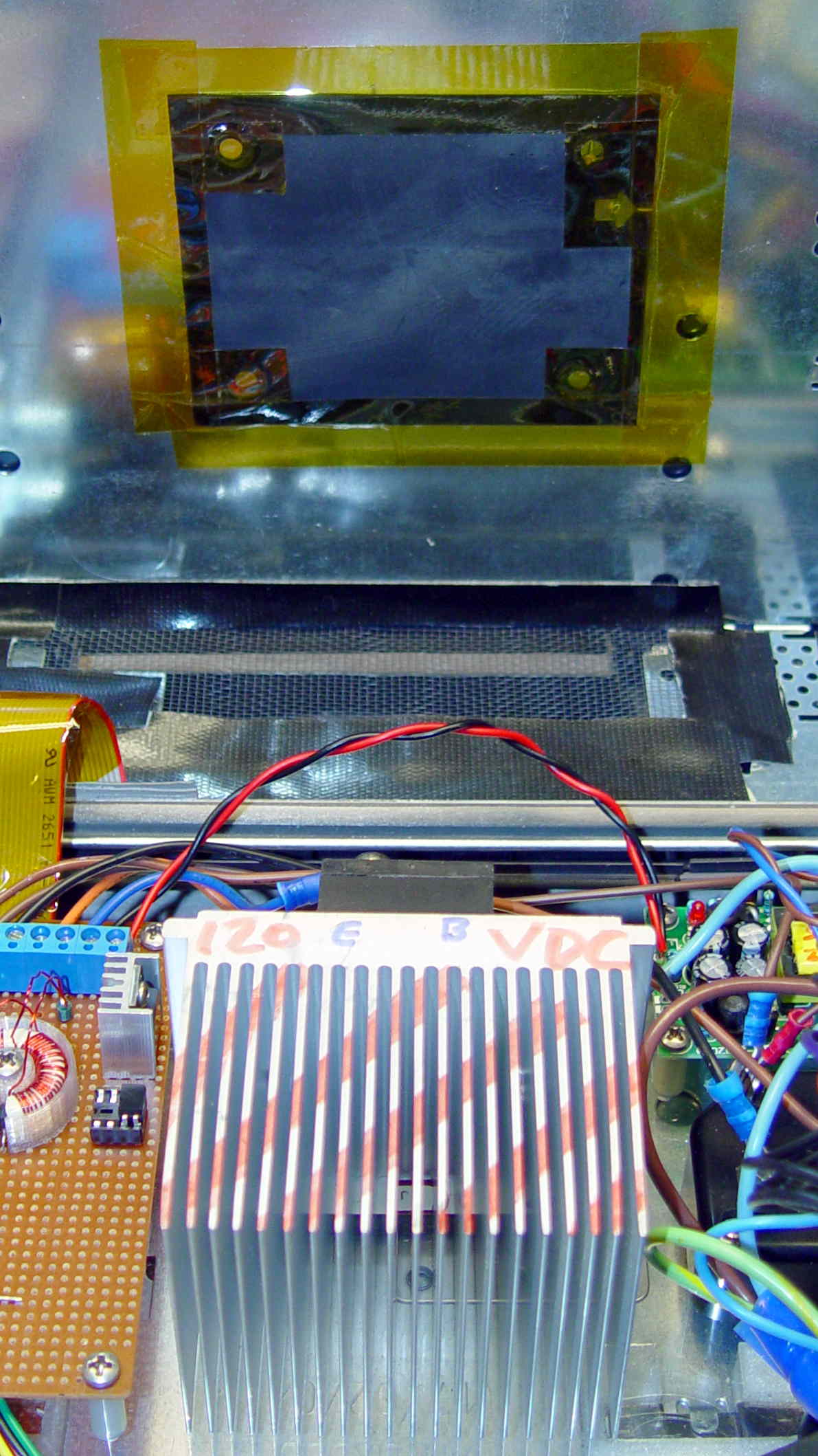
With all those parts safely secured, I ran some end-to-end current measurements from the optoisolator’s LED to the ET227’s collector current, with a safe 10 VDC applied to the collector:
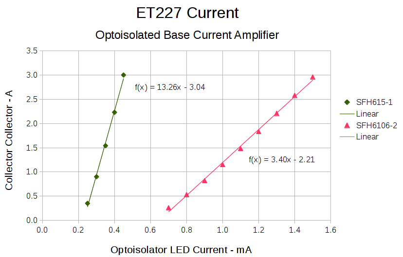
It’s worth noting that the two optoisolators have different pinouts. The DIP socket has wiring for both of ’em, so I could swap the two without rewiring the board. No, I didn’t notice that the first time around.
The curves are nicely linear above 250 mA, which is about what you’d expect for bipolar transistors driven from a current source. Below that, the current into the 13 Ω base-emitter resistor starts to overwhelm the actual base junction current and makes the curves all bendy. Given that the motor doesn’t start spinning the sewing machine with less than half an amp, that region doesn’t matter.
It’s also worth noting that the ET227 normally sees tens of amps (!) into the base terminal to control up to 200 A pulsed collector current with up to 1 kV collector voltage. That puppy loafs along here…
The ratio between the isolator gains doesn’t match the ratio between the spec sheet values, so maybe they’re mismarked or I (once again) have an outlier. In any event, there’s no point in getting too fussy, because the transistor gains depend strongly on temperature. I picked the lower-gain SFH6106-2 for more headroom, but it probably doesn’t make much difference.
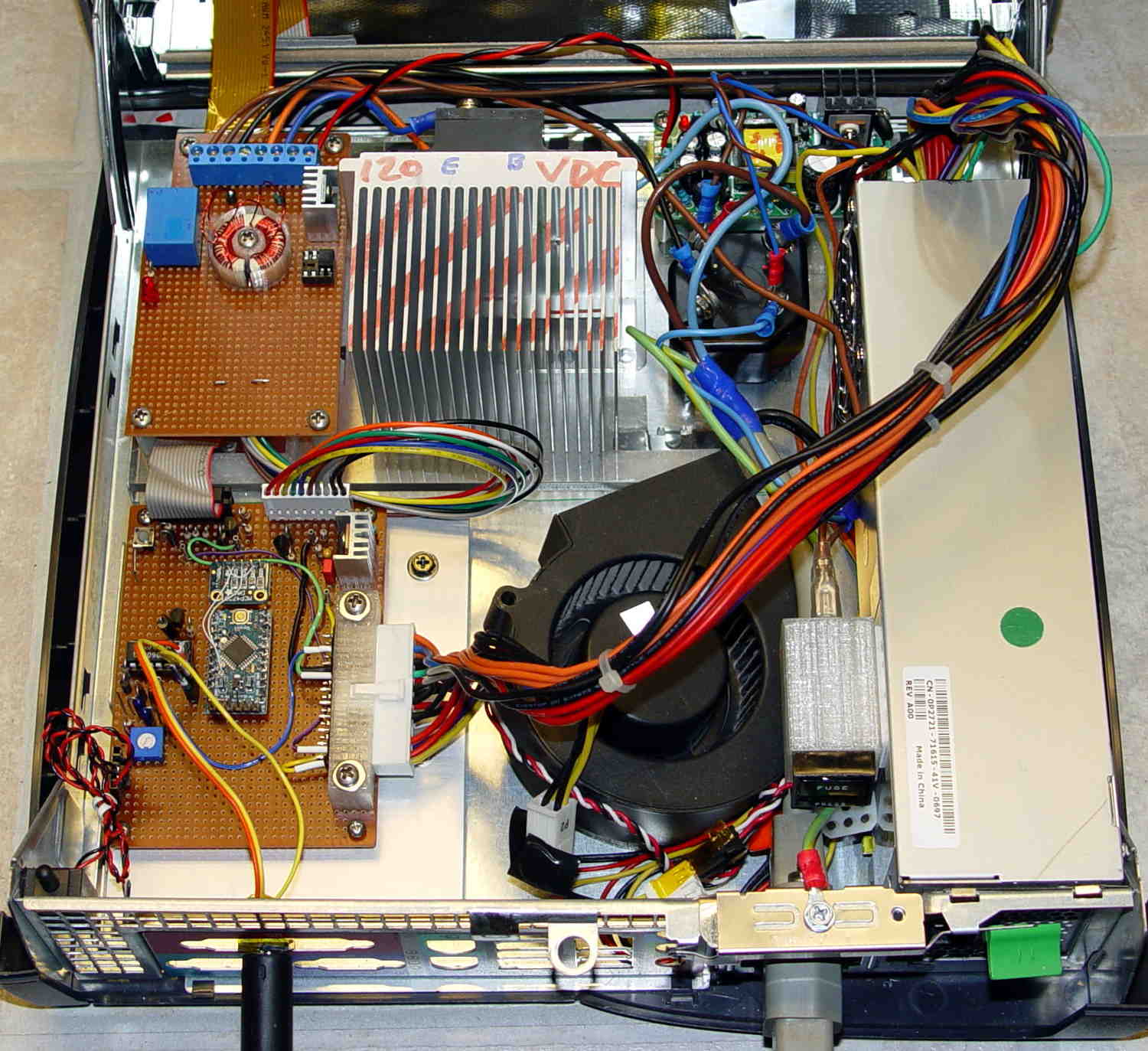
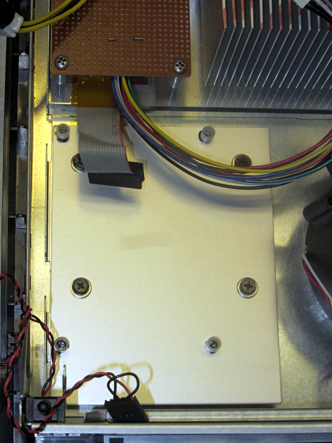
The voltage-to-current circuitry driving the optoisolator’s LED lives on the Low Voltage Interface board, with the MCP4725 DAC breakout board above the Arduino Pro Mini and the rest just beyond the LM324 op amp over on the left:

There’s nothing much to it:
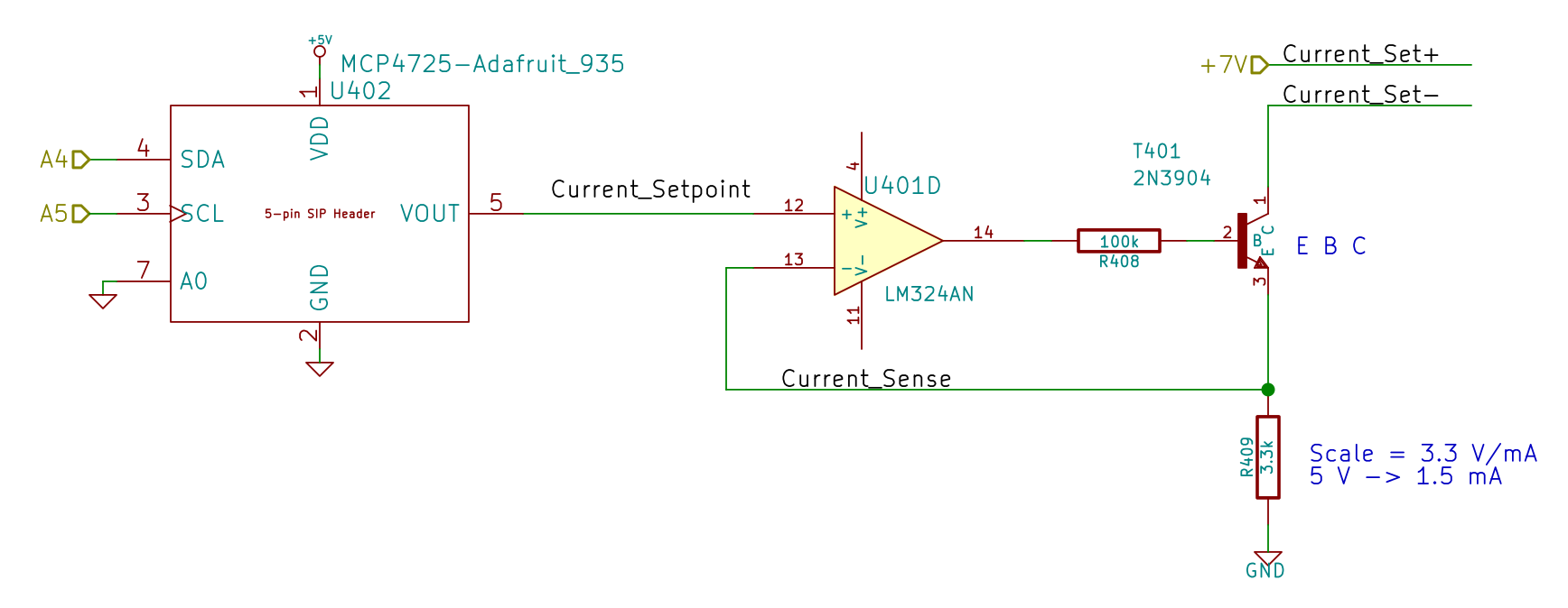
I finally broke down and got some of Adafruit’s nice MCP4725 I2C DAC breakout boards: 12 bits, rail-to-rail output, no PWM ripple. What’s not to like?
R409 scales the gain so that +5 V tops out around 1.5 mA, which should deliver a collector current around 3 A: far more than seems absolutely necessary. R408 lets the op amp develop some voltage while trickling a few dozen microamps into the 2N3904’s base; the hFE runs around 50, so the error due to base current amounts to maybe 2% and, remember, the final current depends on the temperature anyway.
It’s getting closer to working…