The Smell of Molten Projects in the Morning

Ed Nisley's Blog: Shop notes, electronics, firmware, machinery, 3D printing, laser cuttery, and curiosities. Contents: 100% human thinking, 0% AI slop.

Tag: SDR

Software Defined Radios and circuitry

  • LF Loop Antenna: Joint Soldering

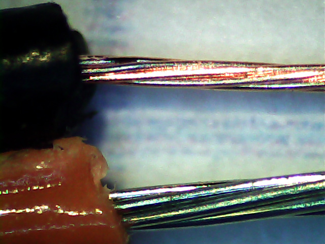
    Given five meters of 40 conductor ribbon cable, the object is to make a 40 turn five foot diameter loop antenna by soldering the ends together with a slight offset. After squaring off, marking, and taping the cable ends, I stripped the wires:

    LF Loop Antenna - wire stripping
    LF Loop Antenna – wire stripping

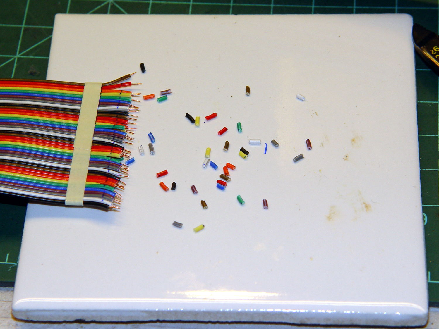
    Twirling those little snippets before pulling them off produced nicely twisted wire ends with no few loose strands. Separate the individual wires, wrap with transformer tape to prevent further separation, run a flux pen along the wire ends, tin with solder, repeat on the far end of the cable.

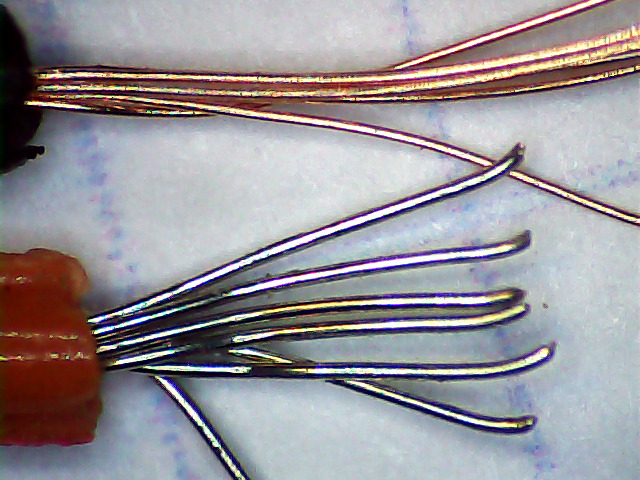
    Tape one end to the ceramic tile. Align the other end with a one-wire lateral offset and the stripped sections overlapping, then tape it down. Slide a paper strip between the ends, passing under every other wire, to separate the top pairs from the bottom pairs, then tape the strip in place:

    LF Loop Antenna - wire prep
    LF Loop Antenna – wire prep

    Grab each left wire with a needle point tweezer, forcibly align with the corresponding right wire, touch with the iron, iterate:

    LF Loop Antenna - top solder joints
    LF Loop Antenna – top solder joints

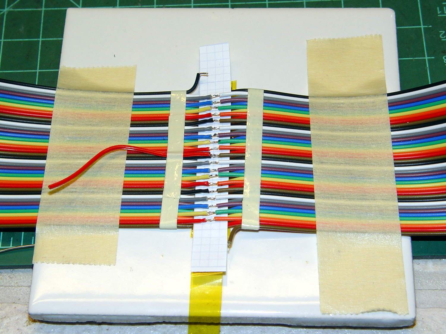
    The red wire trailing off to the left will become the center tap.

    Slide a strip of the obligatory Kapton tape underneath the finished joints, slobber on enough clear epoxy to bond the insulation on both sides of the joints into a solid mass, squish another strip atop the epoxy, smooth down, wait for curing.

    Untape from the tile, flip, re-tape, solder the bottom joints similarly, add Kapton / epoxy / Kapton, and that’s that:

    LF Loop Antenna - complete joint
    LF Loop Antenna – complete joint

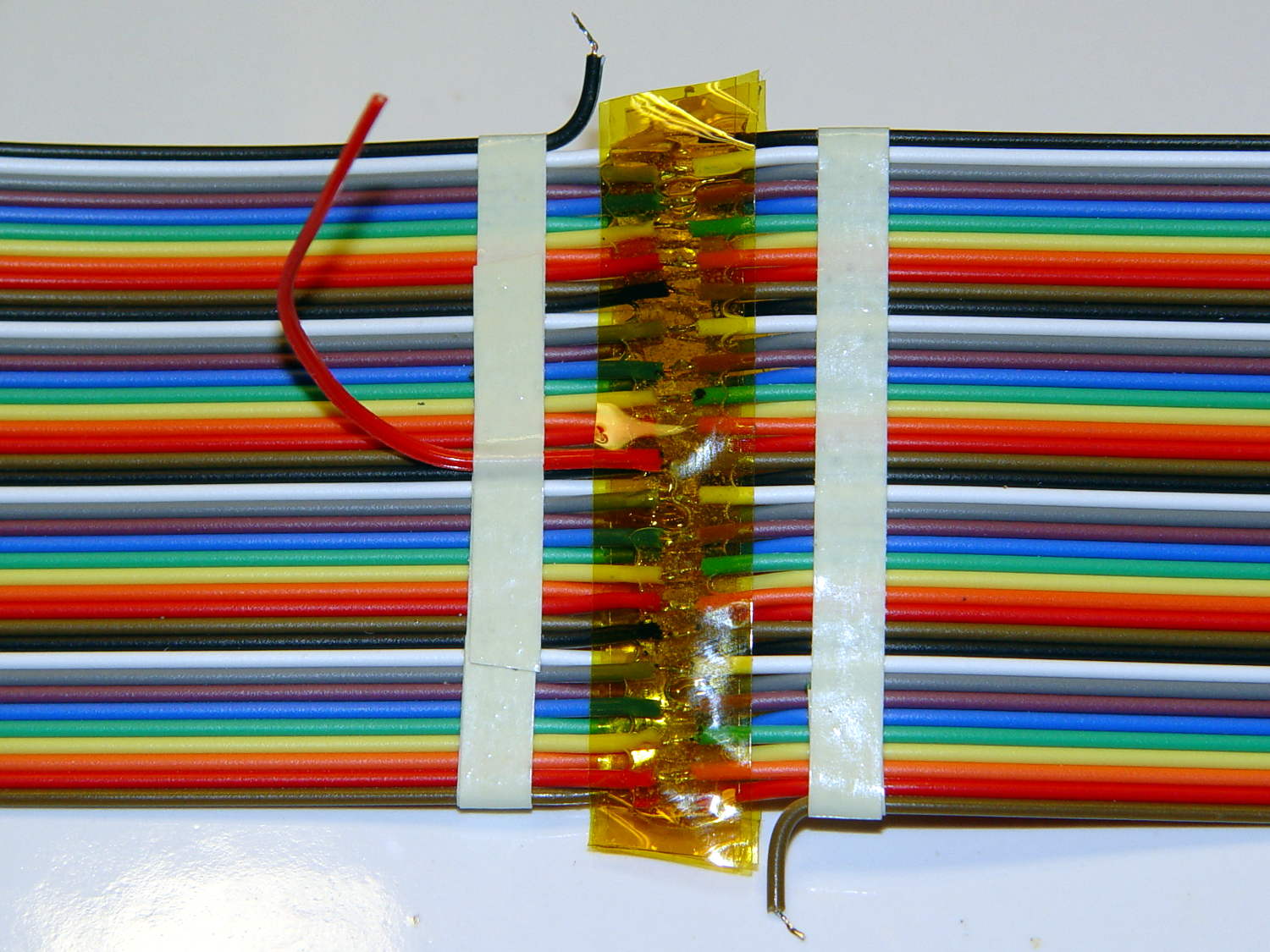
    Prudence dictates checking for end-to-end continuity after you finish soldering and before you do the Kapton + epoxy thing, which is where I discovered I had 80 Ω of distributed resistance along 200 meters of cable. A quick check showed 40 Ω at the center tap and 20 Ω at the quarters (the black wires on the left mark those points), so it wasn’t a really crappy joint somewhere in the middle.

    The joint and its dangly wires cry out for a 3D printed stiffener which shall remain on the to-do list until I see how the loop tunes up.

  • eBay Listings: Read Carefullly

    What’s wrong with this picture? (clicky for more dots)

    eBay - 40 pin IDC cable - header
    eBay – 40 pin IDC cable – header

    Not obvious?

    Here’s the description, slightly reformatted for clarity:

    New 5m IDC Standard 40 WAY 1.8” Multi-Color Flat Ribbon Cable Wire Connector

    Description

    Type: IDC standard.

    10 colors, 4 group, total 40 pcs cables per lot

    5 meter per lot.

    width: 4.7 cm / 1.8 inch

    Package content: 5M Flat Color Ribbon Cable

    If you divide the 1.8 inch cable width by its 40 conductors, you find the wires lie on a 45 mil pitch. If you were expecting this “IDC standard” cable to fit in standard insulation displacement cable connectors with a 50 mil pitch, you’d be sorely disappointed. You can get metric ribbon cable with a 1 mm = 39 mil pitch, but this ain’t that, either.

    Here’s what an individual eBay wire (black jacket) looks like, compared to a wire from a standard ribbon cable (red jacket):

    Ribbon cable - 26 AWG - eBay vs standard
    Ribbon cable – 26 AWG – eBay vs standard

    A closer look at the strands making up the wires:

    Ribbon cable - 26 AWG - eBay vs standard - strands
    Ribbon cable – 26 AWG – eBay vs standard – strands

    As nearly as I can measure with my trusty caliper, the eBay ribbon cable has wire slightly smaller than 30 AWG, made up of seven 40 AWG strands, as opposed to standard 26 AWG wire made of seven 34 AWG strands. The good stuff might be 28 AWG / 7×36 AWG, but I was unwilling to break out the micrometer for more resolution.

    I’d like to say I noticed that before buying the cable, but it came to light when I measured the total resistance of the whole cable: 80 Ω seemed rather high for 200 meters of 26 AWG wire. The wire tables say that’s about right for 31 AWG copper, though.

    Changing the AWG number by three changes the conductor area by a factor of two, so you’re getting less than half the copper you expected. Bonus: it won’t fit any IDC connectors you have on the shelf, either.

    Turns out a recent QEX article suggested building an LF loop antenna from a ribbon cable, so I was soldering all the conductors in series, rather than using connectors, and it should work reasonably well despite its higher DC resistance.


  • Audio Direction Finding

    Given a point source of audio (or RF, for that matter) that’s far enough away to produce more-or-less plane wavefronts, the range difference between two microphones (or ears) is:

    ΔR = (mic separation) x sin Θ

    The angle lies between the perpendicular to the line from the midpoint between the mics counterclockwise to the source source: + for sounds to your left, – for sounds to your right. That’s the trig convention for angular measurement with 0° directly ahead, not the compass convention, but you can argue for either sign if you keep track of what’s going on.

    The time delay between the mics, given c = speed of sound:

    ΔT = ΔR / c

    For microphones 300 mm apart and c = 344 m/s:

    ΔT = 872 µs = 0.3 m / 344 m/s

    If you delay the sound from the mic closest to the source by that amount, then add the mic signals, you get a monaural result that emphasizes, at least a little bit, sounds from that source in relation to all other sounds.

    In principle, you could find the angle by listening for the loudest sound, but that’s a fool’s game.

    There’s an obvious symmetry for a source on the same side, at the same angle, toward the rear.

    A GNU Radio data flow diagram that lets you set the angle and listen to / watch the results:

    Audio Direction Finding.grc
    Audio Direction Finding.grc

    The original doodles show it takes me a while to work around to the answer:

    Audio direction finding doodles
    Audio direction finding doodles
  • SoundTech CM-1000 USB Channel Layout

    Although microphones intended for conference tables aren’t suitable for inconspicuous hearing aids, they go a long way toward working out algorithms (*). This is a SoundTech CM-1000 USB mic:

    SoundTech CM-1000USB microphone
    SoundTech CM-1000USB microphone

    It produces noise-canceled stereo output and a quick test shows impulse sounds produce reasonable left and right responses responses; I can’t vouch for the noise cancelling part.

    A click to the right side:

    CM-1000USB mic - Right pulse
    CM-1000USB mic – Right pulse

    And to the left:

    CM-1000USB mic - Left pulse
    CM-1000USB mic – Left pulse

    The green trace (Channel 2) is obviously the Right channel, which corresponds to in1 on the Scope Sink block and out1 of the Audio Source in the GNU Radio data flow diagram:

    Microphone Time Delay.grc
    Microphone Time Delay.grc

    There’s an irreconciliable clash between 0-index and 1-index numbering in there, but the microphone’s “Left” and “Right” channels appear in the proper places when you look at the mic from the conference room side of the label as shown in the top photo.

    Figuring the speed of sound at 344 m/s, that 100 µs delay means the mic capsules sit 34 mm apart, which looks to be about right, as the flat part of the housing under the label spans 22 mm.

    That’s a tad skimpy for things like beamforming and direction finding, so I actually bought a set with a separate CM-1000 mic that plugs into the USB mic:

    SoundTech CM-1000USB and CM-1000 microphones
    SoundTech CM-1000USB and CM-1000 microphones

    The channel layout diagram explains what’s supposed to happen:

    Soundtouch CM-1000USB microphone channel layout
    Soundtouch CM-1000USB microphone channel layout

    The additional mic changes the response, so that the USB unit becomes the Left channel and the analog mic provides the Right channel. I don’t know what happens to the “noise canceling” part of the story.

    With the mics positioned 200 mm on center, a click to the right side:

    SoundTech CM-1000 mics - 200 mm OC - Right pulse
    SoundTech CM-1000 mics – 200 mm OC – Right pulse


    The eyeballometrically precise 600 µs delay corresponds to 206 mm at 344 m/s, which might actually be close: they’re 200 mm on center, but the Right-channel mic is 10 mm smaller and the mic might be half that much further away from the other one. Not that that makes any difference.

    (*) And, frankly, slapping a mic on the table won’t bother me much at all…

  • Fashion Decoration Accessories: U.FL RF Connectors

    Just like all those EULAs we click through without reading, nobody pays any attention to the Customs declarations on packages:

    U.FL Connectors - Customs declaration
    U.FL Connectors – Customs declaration

    The pick-and-place strip across the top contains ten U.FL connectors, a few of which might make their way onto the Ham It Up board. They cost a grand total of $2.09 (not the $12.00 shown on the label) delivered halfway around the planet in a bit over two weeks.

    I confess: I just couldn’t pass up some new fashion accessories…

  • Ham It Up v1.3 60 kHz Response

    The SMA-to-N cables arrived unexpectedly early, so I fired up the spectrum analyzer to see how the Ham It Up Upconverter behaved at 60 kHz (think WWVB), a smidge below its 100 kHz minimum input frequency spec. It’s worth noting that you can’t do a frequency sweep of the 100 kHz to 50 MHz upconverter response using the tracking generator, because the output sits 125 MHz above the input; yes, it took me a while to dope that out…

    Anyhow, the 60 kHz sine wave from the (sub-audio-frequency up to 2 MHz, 600 Ω -ish output) signal generator, passed through a 5X attenuator, and terminated in 50 Ω:

    Ham-It-Up - 60 kHz input
    Ham-It-Up – 60 kHz input

    It emerges from the H-I-U in Passthrough mode 3.6 dB lower:

    Ham-It-Up - 60 kHz passthru
    Ham-It-Up – 60 kHz passthru

    In Upconvert mode, the output sits 14 dB below the Passthrough output and 17.6 below the input:

    Ham-It-Up - 60 kHz upconvert
    Ham-It-Up – 60 kHz upconvert

    At that span setting, I don’t trust the frequency resolution of that 125.0605 MHz marker readout.

    Cranking the signal generator to produce -10 dBm at the H-I-U output in Passthrough mode brings up a bunch of harmonics:

    Ham-It-Up - 60 kHz harmonics passthru
    Ham-It-Up – 60 kHz harmonics passthru

    In Upconvert, they’re down 13.9 dB from the Passthrough output:

    Ham-It-Up - 60 kHz harmonics upconvert
    Ham-It-Up – 60 kHz harmonics upconvert13.9

    The H-I-U should have about 10 dB conversion loss at 100 kHz, so losing another 4 dB beyond the thing’s rated low end isn’t entirely surprising.

    All in all, it works fine…

  • Ham It Up v1.3 Noise Source Spectrum

    The adapter stack to attach the spectrum analyzer to the Ham It Up noise source turned out to be:

    • N male to BNC female
    • BNC double-male gender bender
    • BNC female to UHF male
    • UHF female to SMA male cable

    Which puts a serious lever arm on the spectrum analyzer end of the chain:

    SMA to N adapter stack
    SMA to N adapter stack

    Ya gotta have stuff, but a pair of cables going directly from the Ham It Up’s SMA female to the analyzer’s N female are on their way around the curve of the planet even as I type.

    That peak at 300 MHz is about +10 dBm, but averaging 25 peak values at each frequency trims off 5 dB and makes it easier to see:

    Noise source spectrum - pk det 25 avg
    Noise source spectrum – pk det 25 avg

    The reference level at the top of the graticule is +30 dBm, not the usual +10 dBm, so the left end of the trace doesn’t obliterate the marker readout.

    So the noise seems good for VHF to UHF projects, which seems reasonable. The noise at the low end falls dramatically with narrower bandwidths, as you’d expect; it’s reasonably flat around -30 dBm below 100 MHz.

    You’d want a bandpass filter in front of whatever you were doing, so as to keep that 300 MHz hash out of everything else.