Ed Nisley's Blog: Shop notes, electronics, firmware, machinery, 3D printing, laser cuttery, and curiosities. Contents: 100% human thinking, 0% AI slop.
Encouraged by the simulation, the 60 kHz preamp hardware sprawls over a phenolic proto board:
60 kHz preamp board – fake antenna
The inductors and resistors hanging off the screw terminals produce more-or-less the same impedance as the real loop antenna. The alligator clips connect a function generator to the secondary winding of a current transformer (used backwards), thus injecting a wee differential signal into the “antenna”.
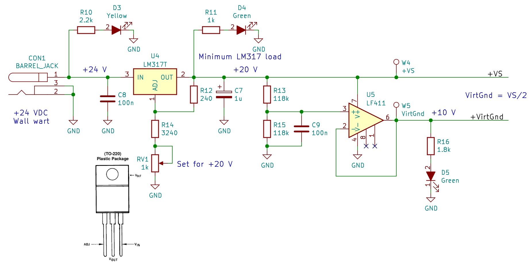
The clump of parts in the lower left knock the 24 VDC wall wart down to 20 V and produce a 10 V virtual ground in the middle:
60 kHz Preamp – power supply – Kicad schematic
The LEDs give a cheerful indication that the power supplies have reported for duty, plus apply a minimum load to the LM317 while I was tinkering. The heatsink gets tolerably warm, so I should dial back or disconnect the LEDs to reduce the load.
The preamp hardware matches the simulated layout, with a few extra bits tossed in:
60 kHz Preamp – Kicad schematic
The weird values come from whatever 1% resistors and silver-mica caps emerged from the heap. The 27 V Zener diodes and 5 kΩ resistors may or may not protect the instrumentation amp inputs from lightning-induced transients.
Because the HP8591 analyzer’s tracking generator starts at 100 kHz, I fed the DDS function generator into the preamp, manually stepped the frequency in 250 Hz increments, and had the analyzer show the maximum response of 19 separate sweeps:
Preamp – max hold – 250 Hz steps
That was tedious and, no, it’s not a comb filter: the actual response skates across the peaks of all those bumps.
The marker shows the preamp bandwidth is 2 kHz, roughly what the simulation predicts; the extremely tight span of that plot makes it look a lot flatter that the usual presentation.
Tightening the span even more shows an unexpected effect:
Preamp – 120 Hz modulation
Those sidebands at ±120 Hz (probably) come from power-line magnetic fields into the “antenna”, because the magnetic field strength depends on the absolute value of the voltage. If they came from the signal generator, they’d be at ±60 Hz: the waveform amplitude depends directly on the voltage.
Having just put a headless Raspberry Pi in the attic, the chip temperature is of some interest. Doing this in an SSH session comes in handy:
watch 'echo "scale=1 ; d = $(cat /sys/class/thermal/thermal_zone0/temp) / 1000 ; print d , \" °C\n\" " | bc'
# blank line to ensure the underscore displays correctly
Raspbian doesn’t have the bc calculator by default, so do that first.
For whatever it’s worth, the Pi starts out at 10 °C and warms over 60 °C under heavy load:
Every 2.0s: echo "scale=1 ; d = $(cat /sys/class/thermal/thermal_zone0/temp) / 1000 ; print d , \" °...  Sat Jan 14 19:58:59 2017

61.7 °C
It ticks along in the mid 30s under light load.
You can run all that in one tab of a terminal window through VNC. If you’ve got that much GUI goin’ on, just add a thermal monitor in the panel and be done with it.
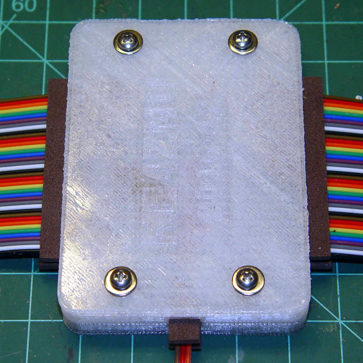
Foam blocks hold the ribbon cable in place and provide a bit of strain relief around the hard plastic edge:
Loop Antenna Splice – hardware
The brass inserts in the bottom block (on the left) got epoxied in place, because they must provide quite a bit of force to clamp the foam. Their larger knurled end sits flush with the outside surface and the smaller end has one thread thickness of clearance below the inner surface.
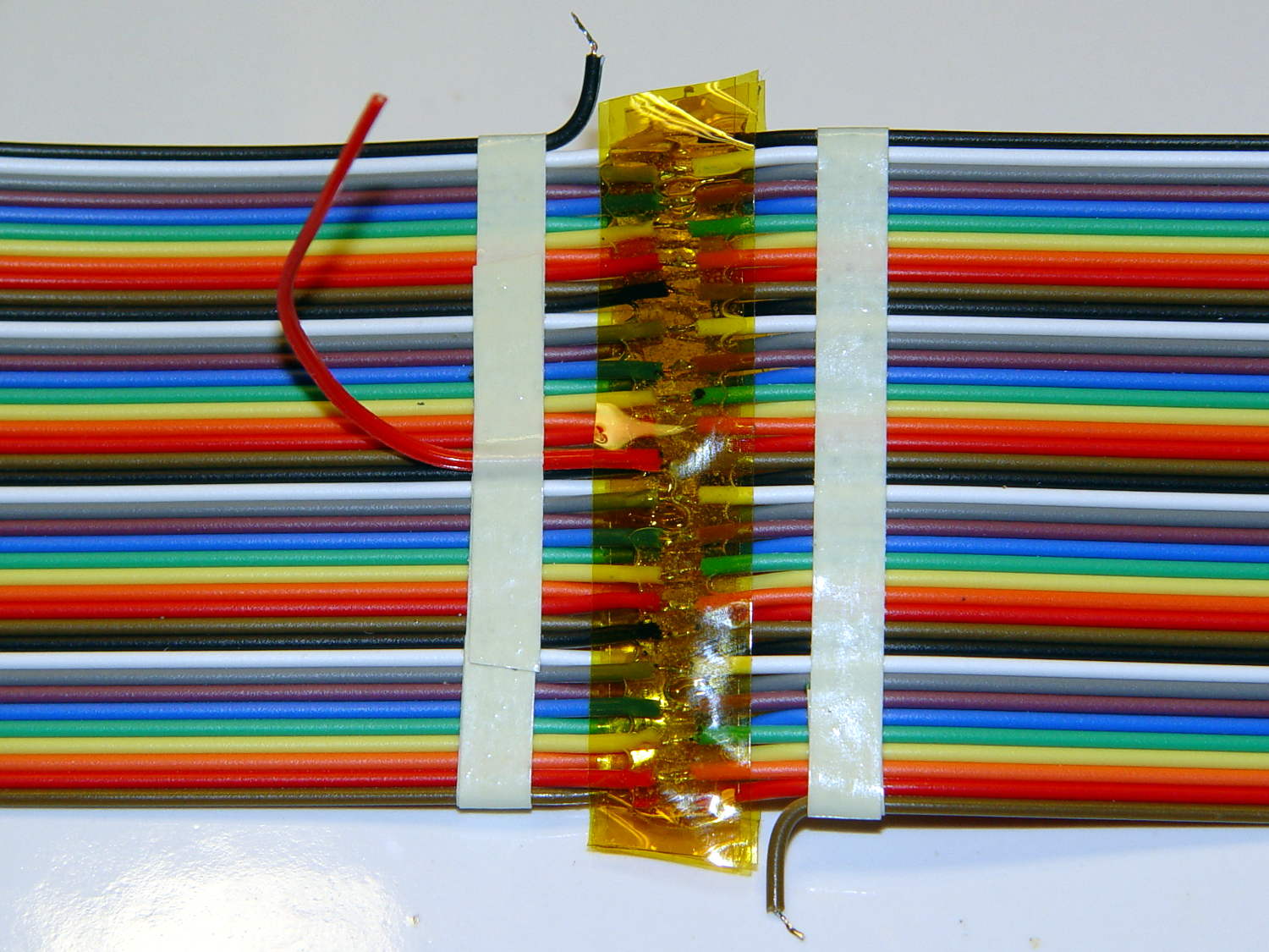
A last look at the wiring:
Loop Antenna Splice – wiring
I think the preamp must sit at some distance from the antenna to prevent feedback, but that remains to be seen.
The M2’s nozzle accumulated a huge blob of PETG that turned into a giant smear:
Loop Antenna Splice – PETG booger
Fortunately, it’s on the inside where nobody will ever see it. If you know where to look, it’s barely visible from the outside.
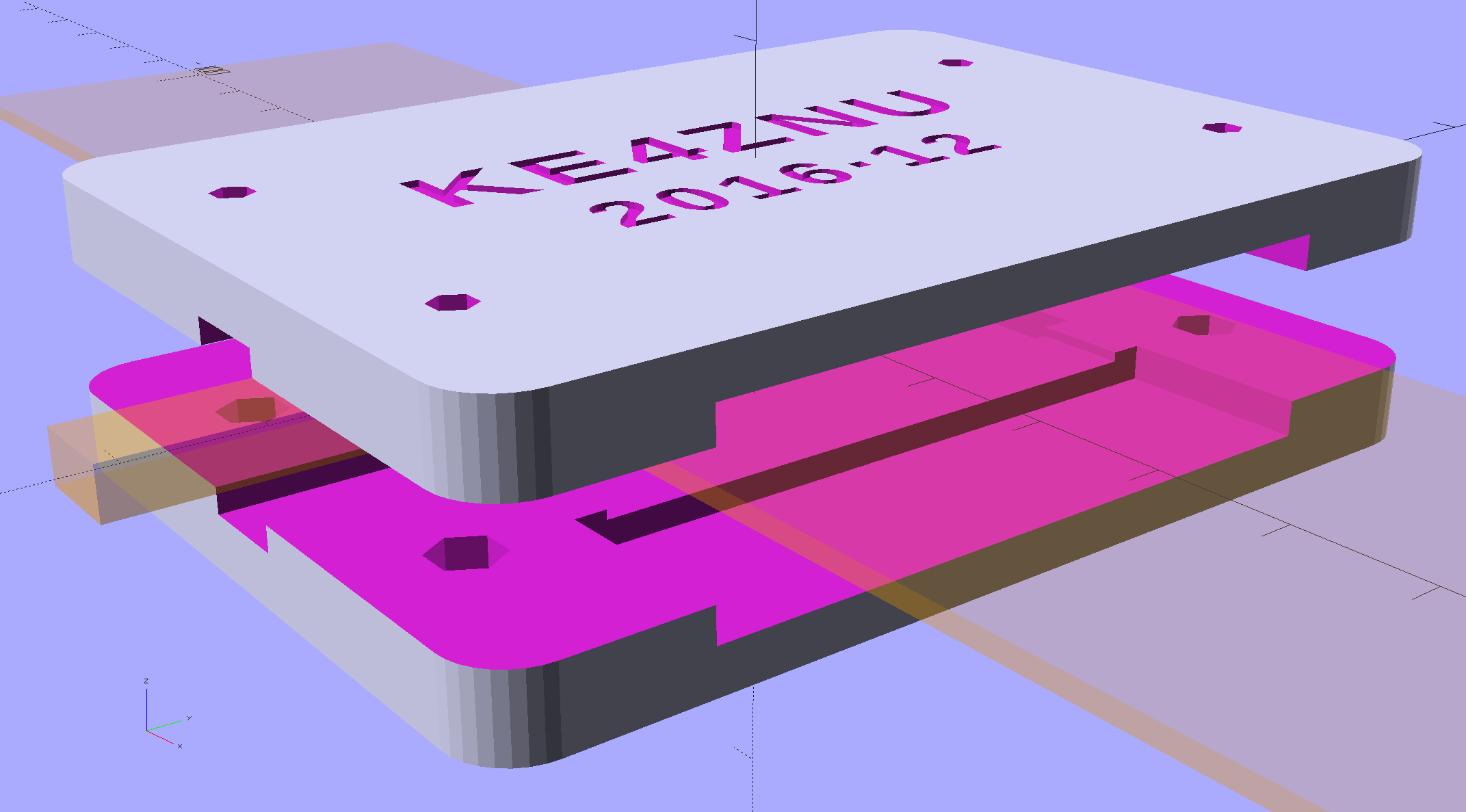
The solid model shows off the structure a bit better:
This file contains hidden or bidirectional Unicode text that may be interpreted or compiled differently than what appears below. To review, open the file in an editor that reveals hidden Unicode characters.
Learn more about bidirectional Unicode characters
This circuitry descends directly from a QEX article (Nov/Dec 2015, p 13) by John Magliacane, KD2BD: A Frequency Standard for Today’s WWVB. The key part, at least for me, is a 60 kHz preamplifier using a resonant-tuned loop antenna and an instrumentation amplifier to reject common-mode interference from local electrostatic fields.
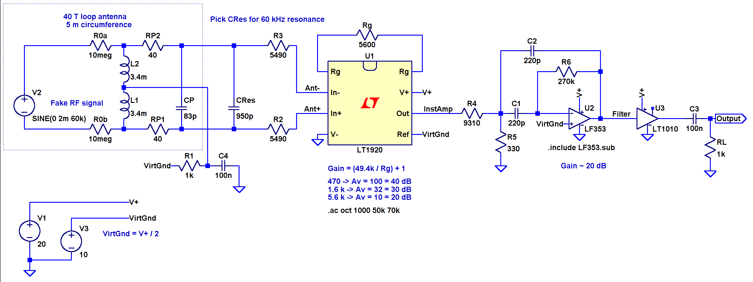
I tinkered up an LTSpice IV simulation using somewhat more contemporary parts (clicky for more dots):
60 kHz Preamp – LTSpice schematic
The simulation quickly revealed that the original schematic interchanged the filter amp’s pins 2 and 3; the filter doesn’t work at all when you swap the + and – inputs.
The stuff in the dotted box fakes the loop antenna parameters, with a small differential AC signal that injects roughly the right voltage to simulate a nominal 100 µV/m WWVB field strength. I biased the center tap to the DC virtual ground at + 10 V and bypassed it to circuit common, so the RF should produce a nice differential signal about the virtual ground. The 5 kΩ resistors provide ESD protection and should help tamp down damage from nearby lightning strikes and suchlike.
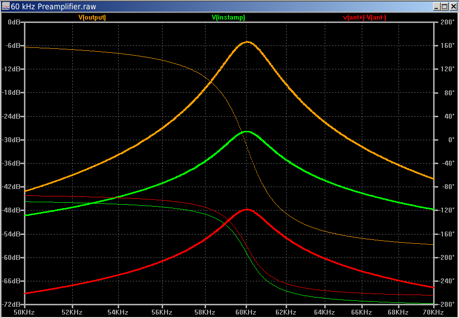
It works pretty much as you’d expect:
60 kHz Preamp – Frequency Response
The LT1920 is mostly flat with 40 dB gain out through 60 kHz, although the actual hardware becomes a nice oscillator with that much gain; my layout and attention to detail evidently leaves a bit to be desired. The LF353 implements a multiple-feedback bandpass filter with about 20 dB of gain; its 4 MHz GBW gives it enough headroom. The LT1010 can drive 150 mA and, with a bit of luck and AC coupling, will feed a 50 Ω SDR input just fine.
This obviously turns into a Circuit Cellar column: March 2017, if you’re waiting by the mailbox.
The topic of function generators came up at Squidwrench a while ago (Sophi was tinkering with LCD shutters) and I finally picked up one of those JYE Tech FG085 DDS function generators to see how they work:
FG085 Fn Gen – in case
Short answer: adequate, if you’re not too fussy.
The board arrived with a bizarre solder defect. It seems a solder stalk yanked one terminal off a ceramic SMD caps:
FG085 – Solder stalk – C26
The schematic and adjacent parts suggested the victim was a 10 uF cap, so I replaced it with one from my stash that worked fine.
However, after soldering enough of the switches to do something useful, the board wouldn’t power up. With a bit of poking around, I discovered the power jack had +15 V from the wall wart, but the center terminals on the DPDT power switch that should have been connected to the jack showed maybe 0.3 V. Jumpering around the failed via and a short trace on the bottom surface let the board power up correctly:
FG085 – Jumpered power trace
If you’re building one of these, solder one pin of each switch, push all the switch caps in place, shove the faceplate over all of them, tape it to the PCB, make sure all the switches are push-able, then solder the remainder of the switch pins. If you do them one by one, you’re certain to end up with a few mis-aligned switches that will either prevent the faceplate from sliding over them or wedge firmly against the side of their assigned hole. Just sayin’.
I tweaked the dimensions slightly to fit the (slightly larger, possibly new, maybe tolerance-eased) front panel, but the bottom mounting screw hole spacing depends on the front panel size, not a specific set of dimensions, leading me to relocate those holes by abrasive adjustment. I didn’t bother with the lid (which doesn’t clear the BNC jack anyway) or the printed plastic feet (having a supply of silicone rubber feet).
The fancy vent gridwork along the sides printed surprisingly well, even in PETG. I’d have gone with larger slots, although I doubt the thing really needs vents in the first place.
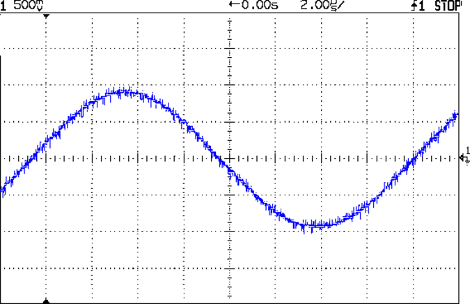
The DDS sine wave output is rough, to say the least:
FG085 Fn Gen – 60 kHz sine
The spectrum shows oodles of harmonic content:
FG085 Fn Gen – 60 kHz sine – spectrum
A closer look:
FG085 Fn Gen – 60 kHz sine – spectrum – detail
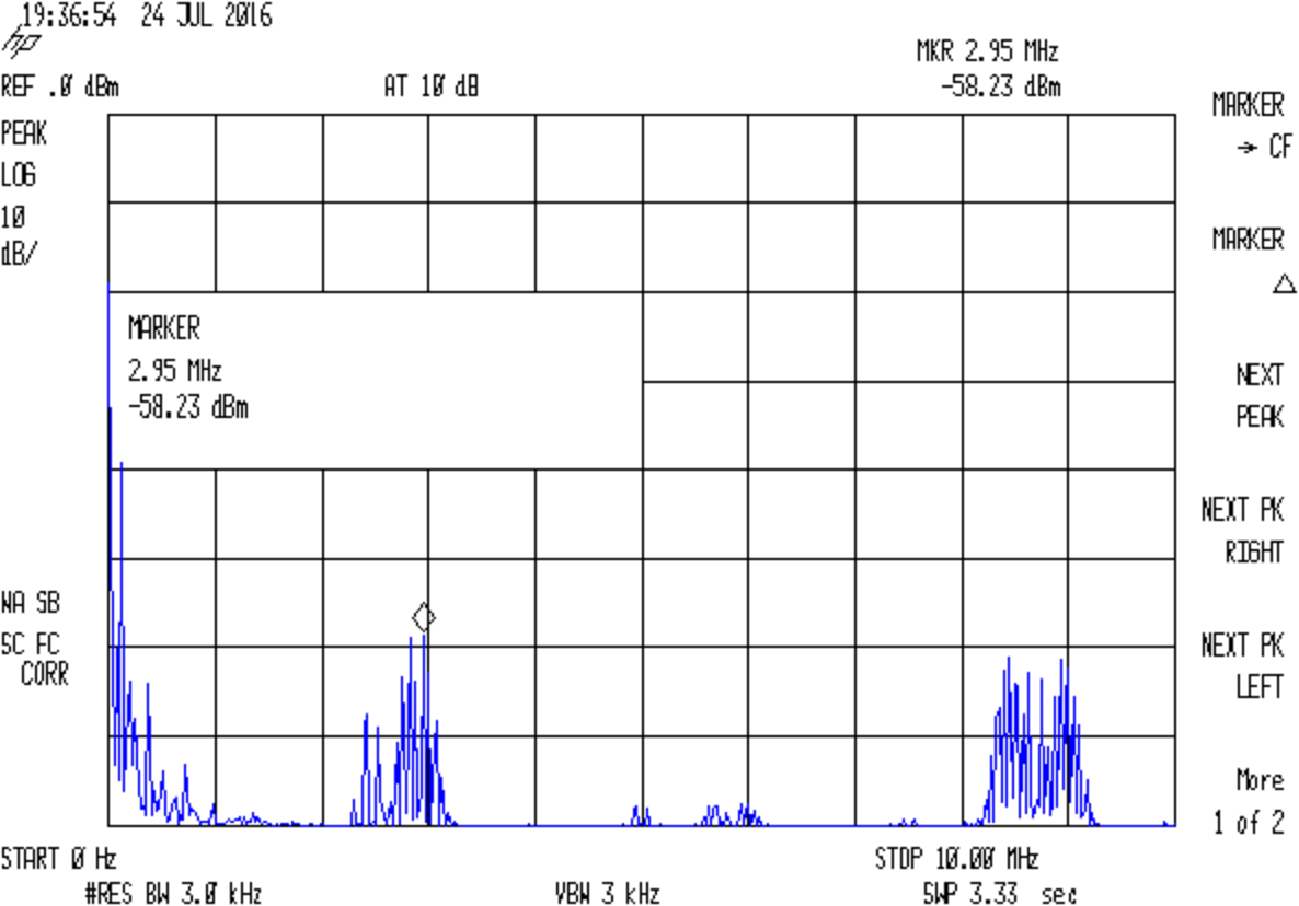
Stepping back a bit shows harmonics of (and around) the 2.5 MHz DDS sampling frequency:
FG085 Fn Gen – 60 kHz sine – spectrum – 10 MHz
For comparison, my old Fordham FG-801 analog function generator has nice smooth harmonics:
FG-801 Fn Gen – 60 kHz sine – spectrum
Closer in:
FG-801 Fn Gen – 60 kHz sine – spectrum – detail
Of course, that crusty old analog dial doesn’t provide nearly the set-ability of a nice digital display.
I stuck some old 12 V 7 A·h batteries in my homebrew power supply for the HP 3801A GPS Time / Frequency Standard, fired it up, put the antenna where it could see a good chunk of the sky, gave it a day to warm up / settle out, and it’s perfectly happy:
------------------------------- Receiver Status -------------------------------

SYNCHRONIZATION ............................................. [ Outputs Valid ]
SmartClock Mode ___________________________   Reference Outputs _______________
>> Locked to GPS                              TFOM     3             FFOM     0
   Recovery                                   1PPS TI -38.3 ns relative to GPS
   Holdover                                   HOLD THR 1.000 us
   Power-up                                   Holdover Uncertainty ____________
                                              Predict  366.2 us/initial 24 hrs

ACQUISITION ............................................ [ GPS 1PPS CLK Valid ]
Satellite Status __________________________   Time _____ +1 leap second pending
Tracking: 4        Not Tracking: 6            UTC      18:22:19     22 Jul 2016
PRN  El  Az   SS   PRN  El  Az                1PPS CLK Synchronized to UTC
  3  34 104   48   * 1  36  48                ANT DLY  0 ns
 17  62 308  103     6  27 220                Position ________________________
 19  39 281   50    11  21  58                MODE     Hold
 28  80 133   64   *22  Acq .
                    24  12 319                LAT      N  41:39:32.328
                    30  15 191                LON      W  73:52:26.733
ELEV MASK 10 deg   *attempting to track       HGT               +82.87 m  (MSL)
HEALTH MONITOR ......................................................... [ OK ]
Self Test: OK    Int Pwr: OK   Oven Pwr: OK   OCXO: OK   EFC: OK   GPS Rcv: OK
scpi >
The FFOM 0 entry says the Frequency Figure Of Merit is “within specifications” of 10-9, averaged over one day. That means the actual frequency should be within 0.010 Hz of 10 MHz.
Feeding the 10 MHz frequency reference into the (equally warmed up) HP 8591E spectrum analyzer and selecting an absurdly narrow span produces a comforting sight:
HP Z2801A GPS Receiver – 10 MHz ref – HP 8591E
Given the horizontal resolution, that’s dead on 10 MHz.
The object of soldering all 40 wires in the 5 m hank of ribbon cable in series is to build a 40 turn loop antenna to receive LF radio signals like WWVB at 60 kHz. The antenna, being basically a big coil of wire, will have an inductance that depends on its layout, so putting a capacitor in parallel turns it into a resonant tank circuit. Given a particular layout (and, thus, an inductance), you can choose the capacitor to make the antenna resonant at whatever frequency you need (within reason).
With the joints soldered & reinforced with epoxy, the inductance across all 40 turns:
535 µH – rolled into a compact bundle
6.66 mH – vaguely circular loop on the concrete floor
5.50 mH – lumpy rectangle on the concrete floor
Back in a slightly different circular layout on the floor:
6.8 mH – across all 40 turns, as above
2.0 mH – across either set of 20 turns from the center tap
Given that inductance varies as the square of the number of turns, you’d expect a factor of four between those two inductances, but that’s not how it worked out.
Hanging the loop from a pair of screws in the floor joists to make a droopy rectangle-oid shape and driving it from a 600 Ω signal generator through a 10 kΩ resistor, it’s self-resonant at 213 kHz. Repeating that with a 470 kΩ resistor drops the resonance to 210 kHz, which isn’t different enough to notice and surely has more to do with my moving the loop while dinking with resistors.
Adding parallel capacitance (measured with an LCR meter, just to be sure) changes the resonance thusly:
9.9 nF → 20 kHz
900 pF → 64 kHz
400 pF → 87 kHz
250 pF → 108 kHz
none → 213 kHz
Because the resonant frequency varies inversely as the square root of the capacitance, halving the resonant frequency means you’ve increased the capacitance by a factor of four. Because 250 pF halves the frequency (mostly kinda sorta close enough), the loop’s stray capacitance must be about 1/3 of that: 83 pF.
Yeah, 1/3, not 1/4: the additional capacitance adds to the stray capacitance, so it goes from 83 pF to 250 + 83 pF = 333 pF, which is four times 83 pF.
The self-resonant frequency of 213 kHz and the 83 pF stray capacitance determines the loop inductance:
L = 1/((2π · 213 kHz)^2 · 83 pF) = 6.9 mH
Pretty close to the measured value from the floor, I’d say.
To resonate the antenna at 60 kHz, the total capacitance must be:
60 kHz = 1/(2π · sqrt(6.9 mH · C)) → C = 1050 pF
Which means an additional 1050 – 83 = 970-ish pF should do the trick, which is about what you’d expect from the 64 kHz resonance with the 900 pF cap above. I paralleled pairs of caps until it resonated at 59.9 kHz.
The -3 dB points (voltage = 1/sqrt(2) down from the peak) turned out to be 58.1 and 60.1 kHz, so my kludged caps are slightly too large or, once again, I nudged the loop.
Figuring Q = (center frequency) / bandwidth = 59.1 / 2 = 30, which works out close enough to Q = X / R = 2600 / 80 = 33 to be satisfying. Using standard 26-ish AWG ribbon cable, rather than crappy 31-ish AWG eBay junk, would double the conductor area, halve the series resistance, and double the Q. Faced with that much resistance, I’m not sure better caps would make any difference.
Attaching the spectrum analyzer through a 470 Ω resistor to reduce the load:
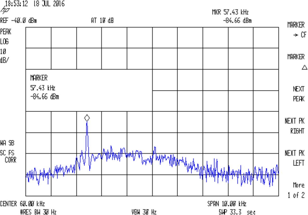
Loop – 40T 1nF – spectrum
I’d love to believe that big peak over on the left at 57.1 kHz is WWVB, but it’s not.
What’s more important: the broad hump between 56 and 62 kHz, where the increased amount of background hash suggests the antenna really is resonant, with a center frequency around 59 kHz. The -3 dB points might be 57 and 61 kHz, but at 10 dB/div with 5 dB of hash, I’d be kidding myself.
Dang, I love it when the numbers work out!
It’s faintly possible the spectrum analyzer calibration is off by 2.5 kHz at the low end of its range. The internal 300 MHz reference shows 299.999925 and it puts FM stations where they should be, but the former could be self-referential error and the latter lacks enough resolution to be comforting. I must fire up the GPS frequency reference, let it settle for a few days, see whether it produces 10.000000 MHz like it should, then try again.