Ed Nisley's Blog: Shop notes, electronics, firmware, machinery, 3D printing, laser cuttery, and curiosities. Contents: 100% human thinking, 0% AI slop.
After the deck stain cured for a few days, I replaced the dryer vent:
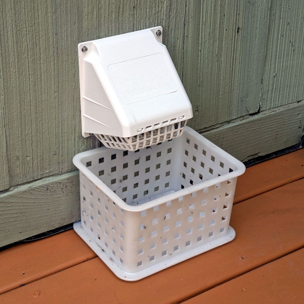
Dryer vent
The alert reader will note it’s held to the siding with four stainless steel 4 mm socket-head cap screws, for which I’m not going to apologize one little bit.
They fit into a quartet of threaded wood inserts driven into the siding, because the previous vent had small steel screws that pulled out many years ago.
I used a 4-¼ inch oscillating hole saw to embiggen the original 4.000 inch hole through the wall that doesn’t fit contemporary “4 inch” dryer vent pipe. The 4.000 inch hole in the interior seal plate also needed embiggening.
We must add a filter bag of some sort, as the dryer really wants to coat the deck in fuzz, but that’s in the nature of fine tuning.
There are no other pictures, as this was a ten minute job that burned an entire afternoon …
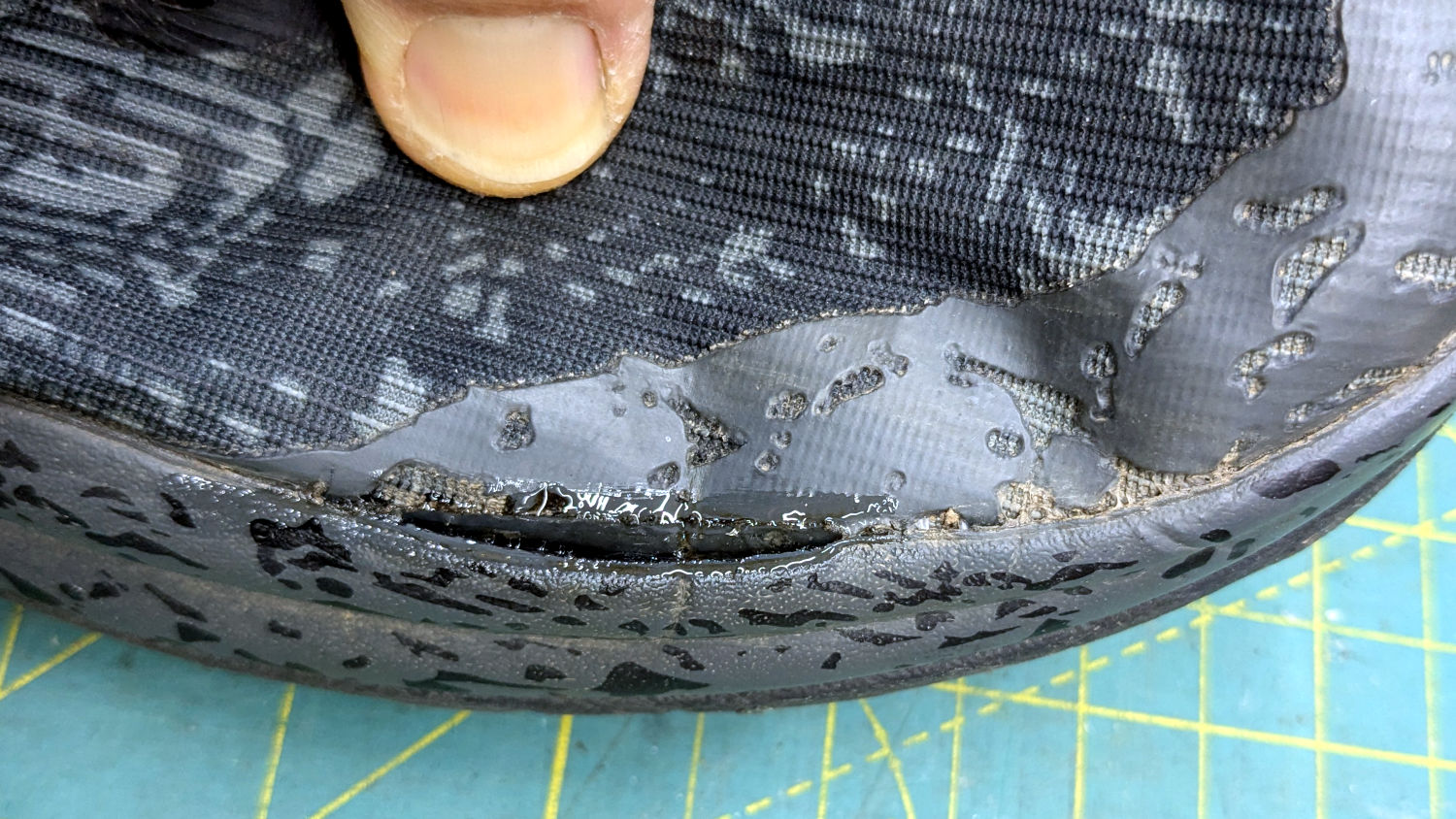
Mary got a pair of HOKA shoes in the spring and, after a few months of what we consider light usage, had the upper detach from the sole:
HOKA shoe – failed joint
The oddly shaped holes in the rubberized area are a stylin’ thing, not defects.
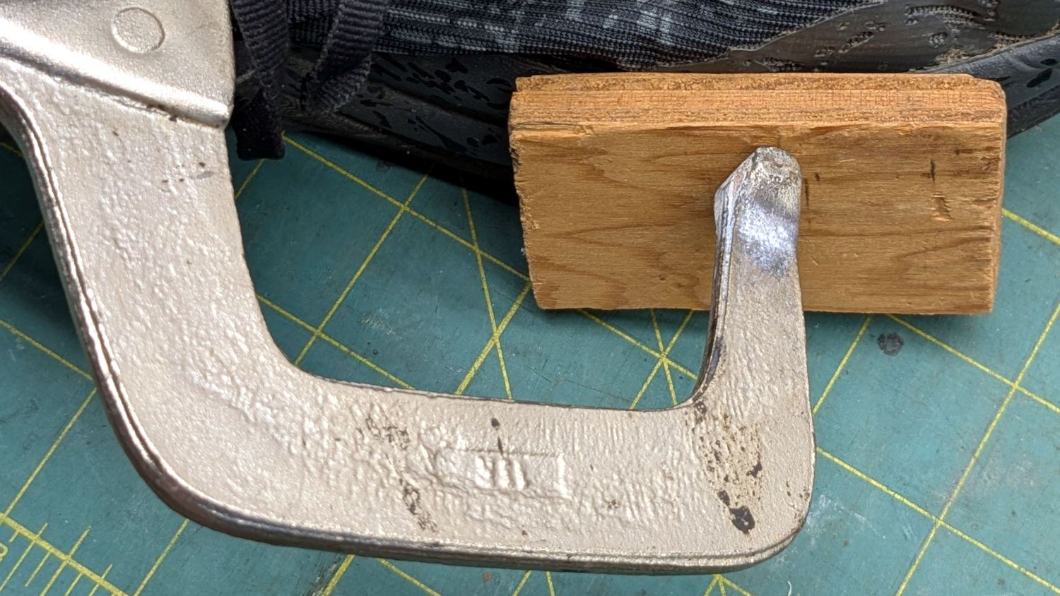
The wet-looking stuff is E6000+ adhesive, which then got clamped overnight:
HOKA shoe – clamping
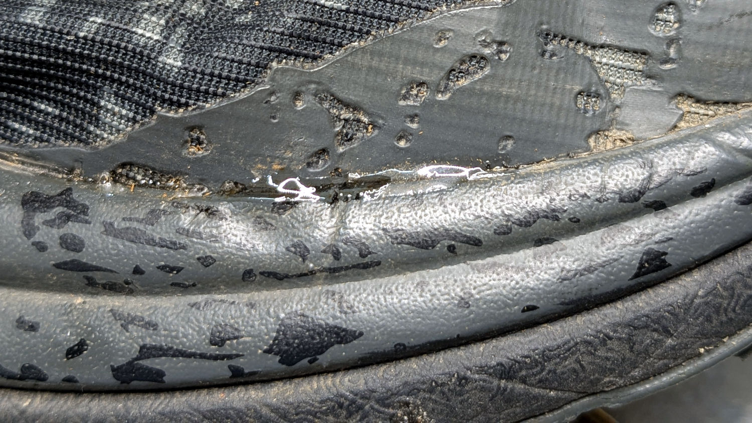
It cured and seems to be holding the pieces together:
HOKA shoe – glued
HOKA shoes came highly recommended by a friend and carry a corresponding price tag. Mary felt expensive shoes should hold together better than that, so (before I undertook the repair) she returned them under warranty. Some weeks later, the shoes reappeared with a note describing the failure as “normal wear and tear” which is not covered by the warranty.
Whereupon I was given permission to have my way with them.
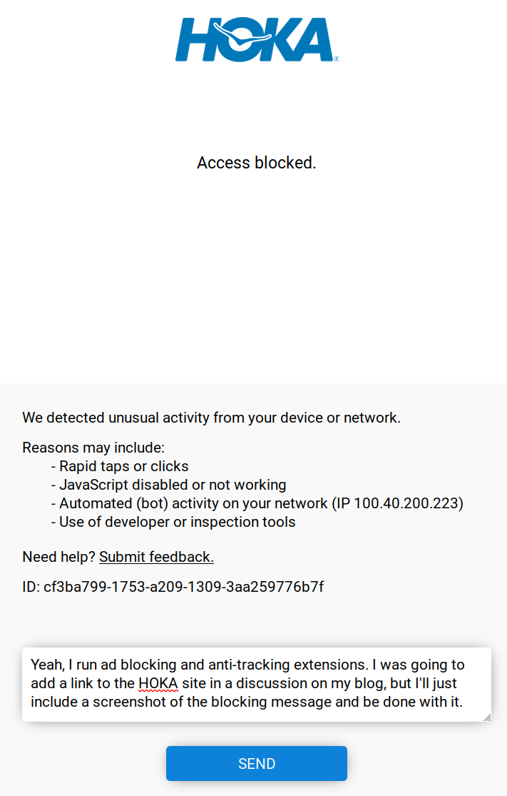
For whatever it’s worth, this also happened:
HOKA site blocking
Mary’s conclusion was they’re nice shoes and fit well, but they’re definitely not worth three times the price of the shoes she’d been wearing.
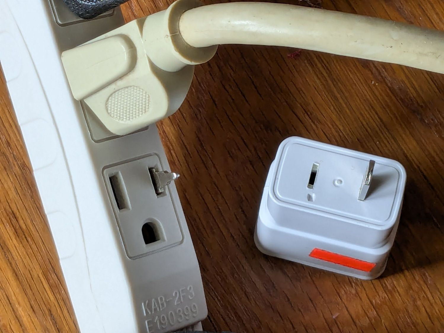
Mary reported a problem unplugging the USB charger powering the light pad (the successor to the pad I repaired) she uses for quilting layouts:
USB Charger – as found
Yes, that blade is sticking out of the hot (“Line”) side of the outlet.
The only way into the charger was through its other end:
USB charger – interior top
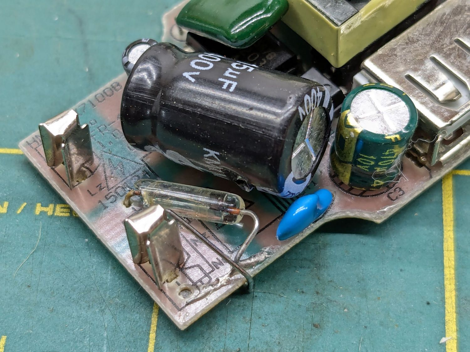
Because I had no intention of returning it to service, I tried pushing the errant blade back in place, only to have it overshoot the mark and bulldoze various parts aside:
USB charger – PCB blade contacts
The two upright shapes contact the blades, but do not lock them in place. The PCB pulled easily out of the case, with no objection from the remaining (“Neutral”) blade.
The blades are simple steel bars press-fit into the plastic case, without holes / dimples / notches to lock them into the plastic. As far as I could tell, they were not molded in place.
I tossed the corpse into the e-waste box, extracted another USB charger from the Box o’ USB Chargers and returned the light pad to service.
I do have a few Genuine UL Listed USB chargers, but these are not among them.
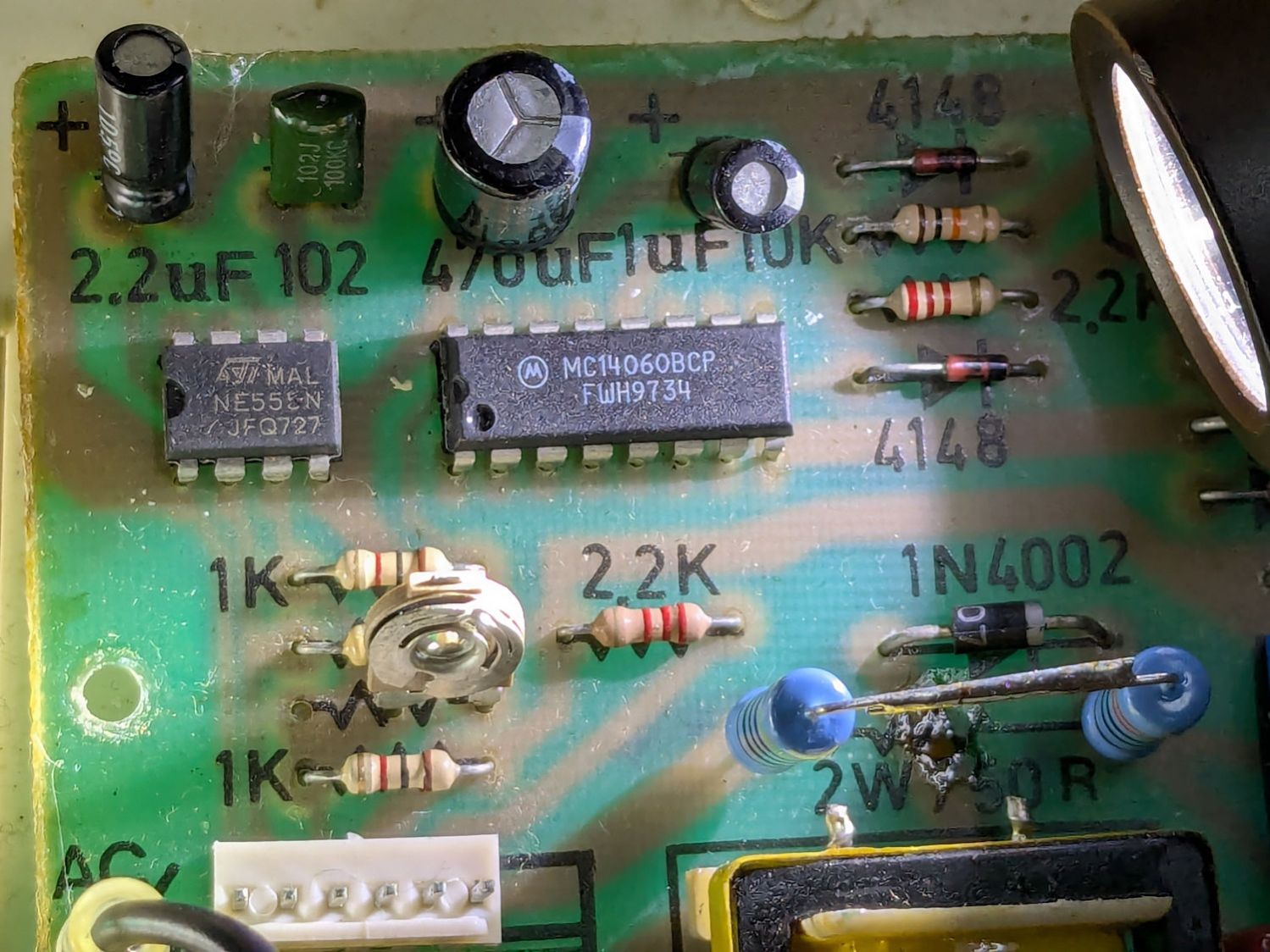
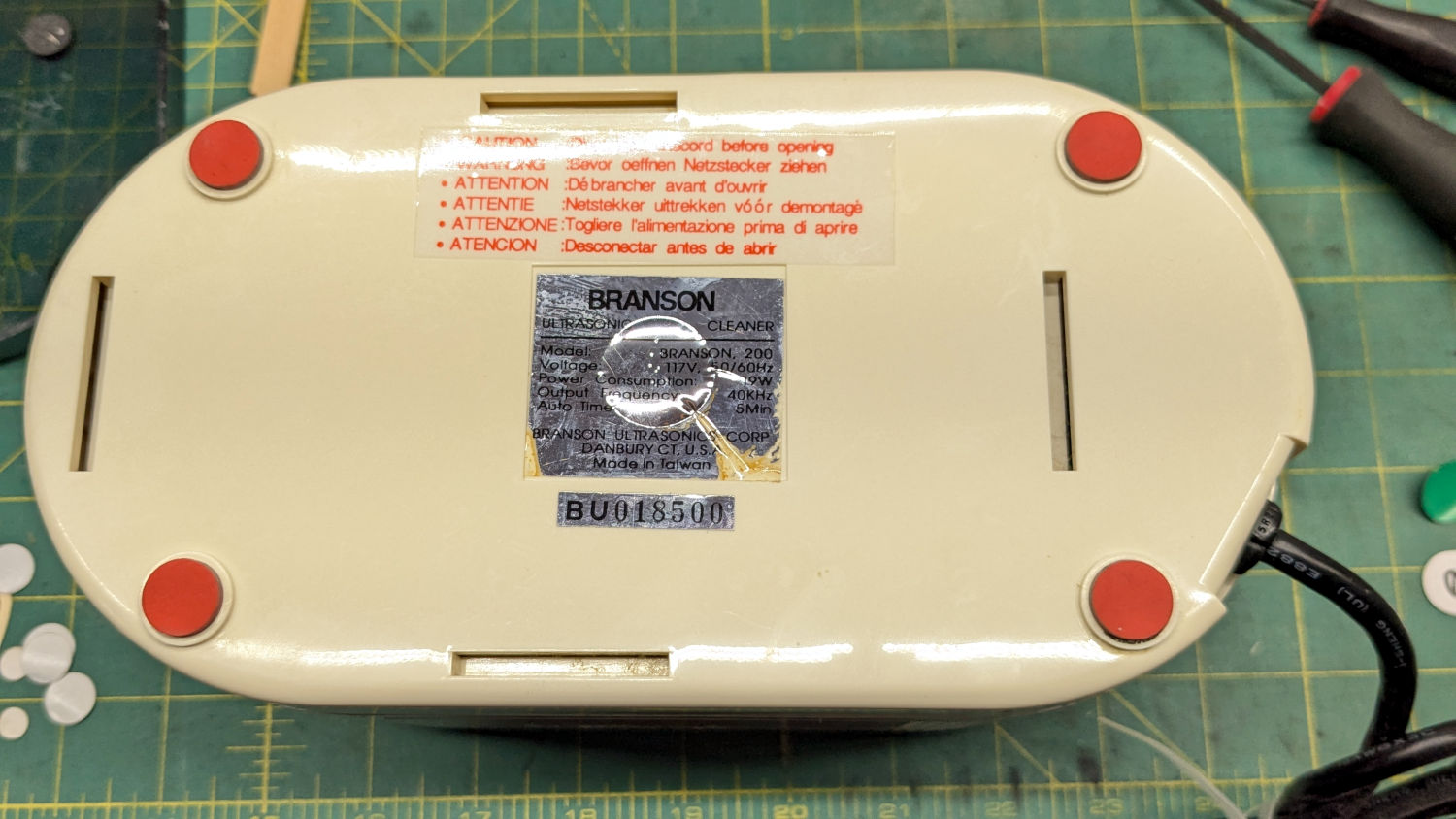
The Branson 200 ultrasonic cleaner in the bathroom has been with me for a long time. If I’m reading the IC date codes correctly, it’s one of the first things I bought after real paychecks began arriving back in 1974:
Branson 200 ultrasonic cleaner – IC date codes
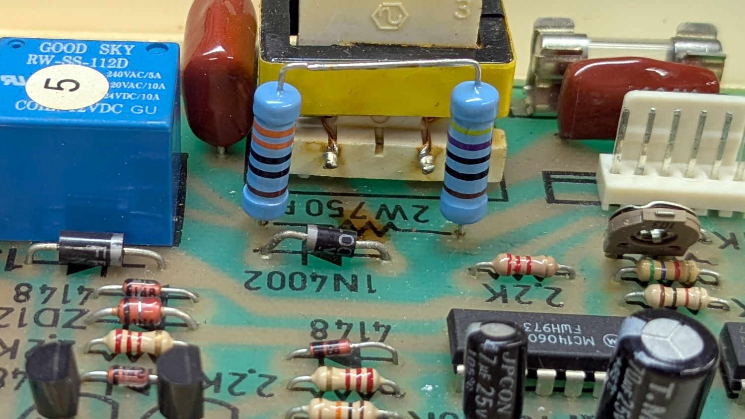
The circuit board has that spacious old-time layout:
Branson 200 ultrasonic cleaner – PCB overview
Believe it or not, this isn’t why I took the thing apart:
Branson 200 ultrasonic cleaner – charred resistor
I’ve never seen a PCB with the component values printed on it, but they definitely came in handy!
That resistor measured 743 Ω: still good, even with an extra-crispy coating.
Assuming it was dissipating a bit more than its 2 W rating could handle, I replaced it with a 470 Ω + 330 Ω series combination of 2 W 1% metal film resistors:
Branson 200 ultrasonic cleaner – retrofit resistors – top
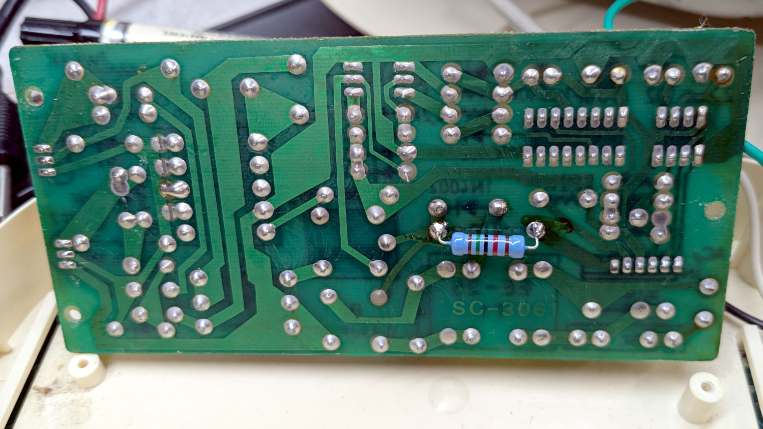
In parallel with a 15 kΩ resistor on the back of the PCB to bring them down to 759 Ω:
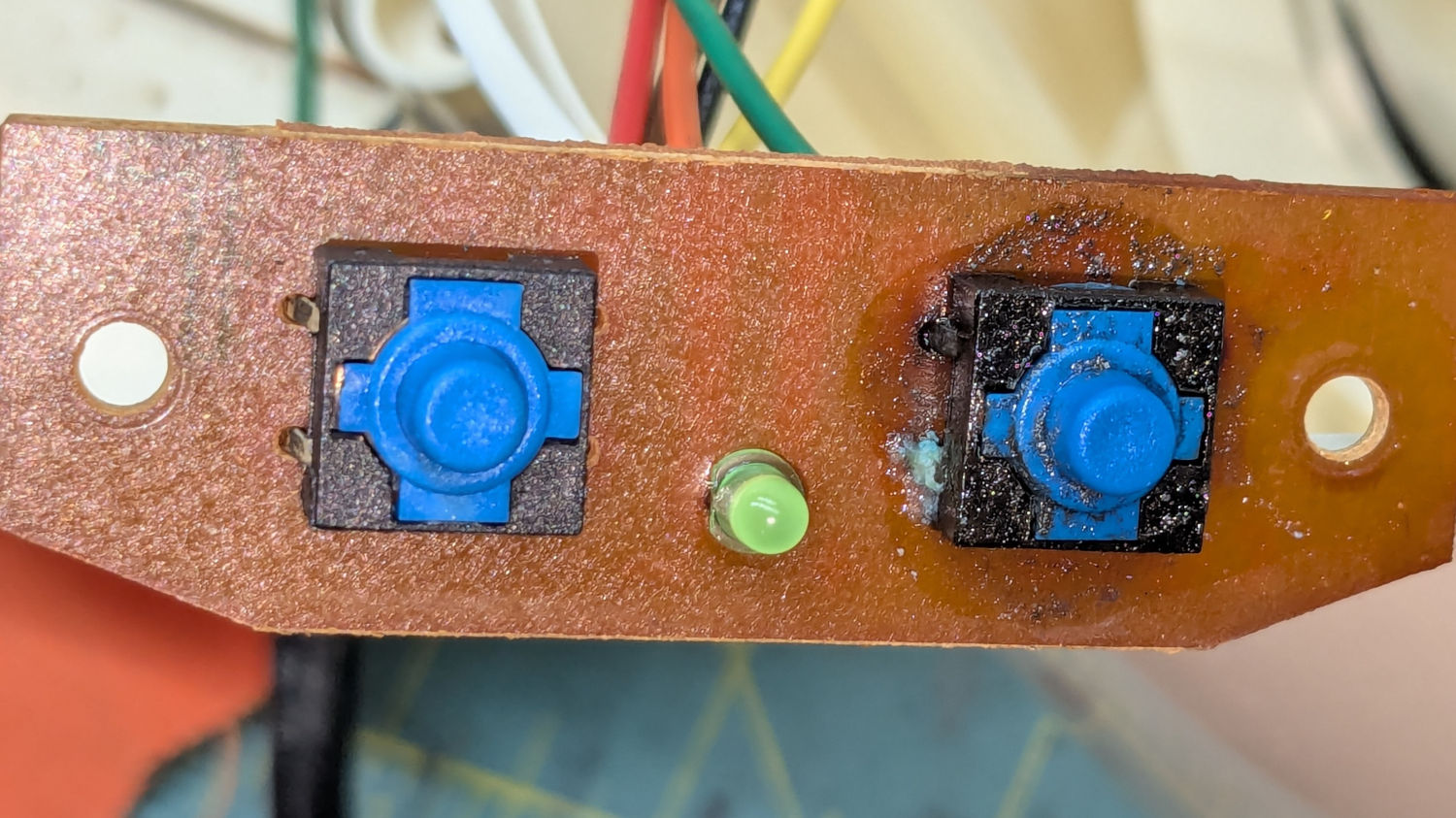
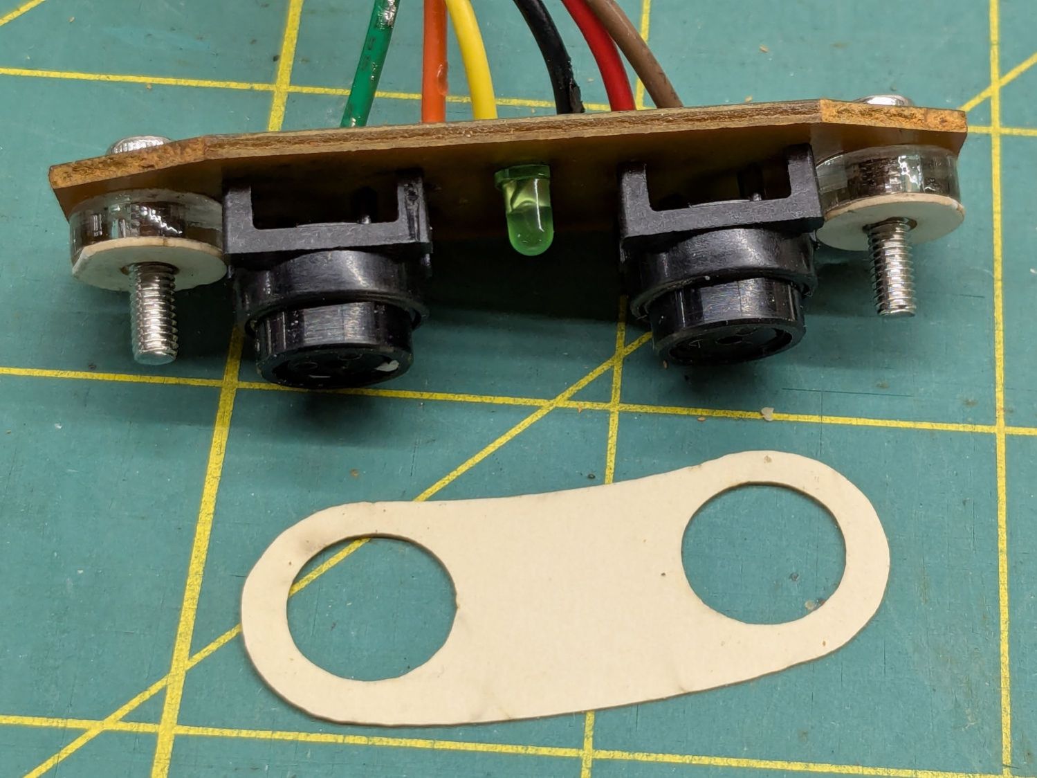
Well, almost perfectly. The original case holes were a snug fit around a 25/64 inch = 9.8 mm drill , so I hand-twisted X and Y drills (10.1 and 10.3 mm, respectively) to embiggen the holes for a loose fit around the new switches.
The two small plastic disks + paper shims hold the PCB just far enough away from the case to put the switch actuators flush with the case surface, with 12 mm M3 SHCS replacing the original 6 mm screws.
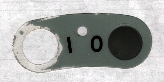
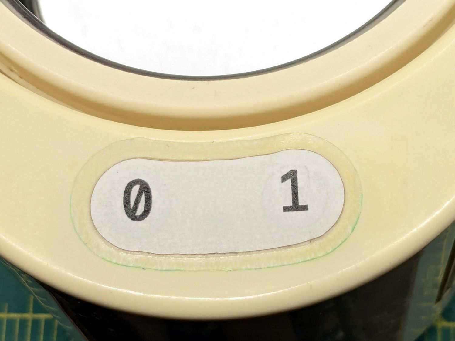
The cardboard test piece came from the usual scan of the original switch cover and, after a few iterations, we now have a stylin’ paper replacement:
The transparent cover with greenish edges is transfer tape intended for vinyl sheets, which will likely not survive very long at all. It’s outset 3 mm from the paper label, just barely enough to get any traction at all on the case.
While I was at it, I replaced the worn black rubber feet with fancy red stamp-pad rubber feet:
For the record, only two screws secure the top & bottom parts of the case. They’re on the power-cord end of the bottom, so those are the only two feet you must peel off to get inside.
All of which put the cleaner back in operation while I figure out what kind of tape will seal the power switches more permanently.
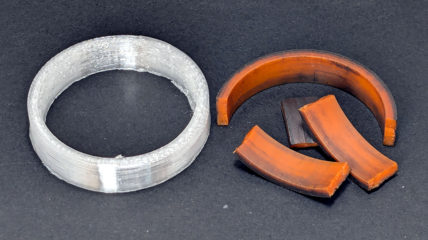
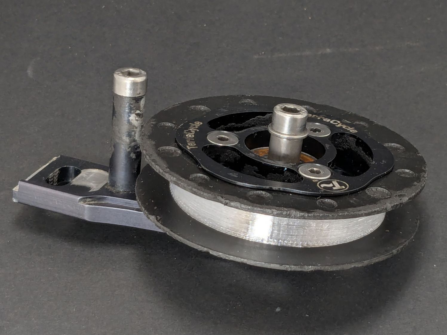
The Terracycle (now T-cycle, for reasons presumably involving the transfer of money) chain return idlers on our Tour Easy bikes developed hardening of their urethane tires:
Terracycle Idler tire – printed vs OEM
Urethane shouldn’t crack like that, but after more than fifteen years, stuff wears out.
The white ring is 95A TPU printed on the Makergear M2, which is definitely more flexy than the original tire, but has the redeeming feature of being both Good Enough and trivially easy to model:
include <BOSL2/std.scad>

NumSides = 4*3*2*4;
$fn=NumSides;

Thick = 3.5;
ID = 46.4;
OD = ID + 2*Thick;
Length = 11.2;

tube(Length,id=ID,od=OD,anchor=BOTTOM);
It printed with 5 mm brims on both the ID and OD, because TPU has the barest adhesion to the M2’s glass plate + hair glue. There’s a long-unopened box now on the bench with a BuildTak PEI surface (thank you: you know who you are!) that should improve the situation.
In any event, the tires fit well:
Terracycle Idler tire – installed
The layer-to-layer adhesion isn’t as good as I think it should be, so I’ll likely use those tires as testcases for tweaking the new build plate & settings.
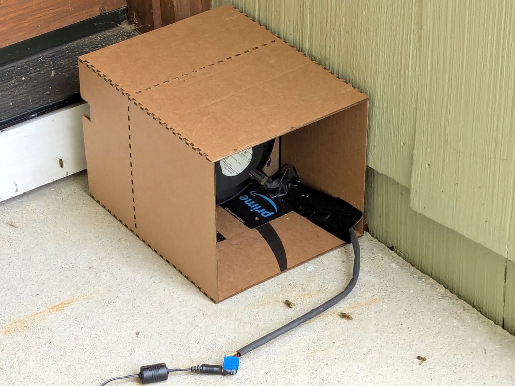
A colony of Yellowjacket wasps moved into a gap somewhere inside our front door, which we noticed only after they set up a heavy traffic pattern over the front step. The nest is far enough up inside the door frame (or, shudder, the wall) to be immune to rattlecan insecticide spray and the wasps simply tiptoe across sticky-trap sheets laid on their entrance paths.
That’s a hulking 12 V electronics case fan mounted on a cardboard bulkhead inside what’s basically a tunnel, with its power supply plugged into a widowmaker extension cord screwed into the light fixture next to the door.
The fan blows away from the door, with the general idea of killing wasps leaving the nest. Arriving wasps can walk home around the box, but departing wasps always take flight from the small crack under the door sill, whereupon they’re sucked into the fan, shattered by the blades, and blown out onto the step.
A Yellowjacket can make headway into a 1 m/s wind, but not for very long, which explains why most of them prefer walking home.
The carnage looks awful, so it seems to be working …