Ed Nisley's Blog: Shop notes, electronics, firmware, machinery, 3D printing, laser cuttery, and curiosities. Contents: 100% human thinking, 0% AI slop.
A winning entry in the “The Bigger the Blob, the Better the Job” category:
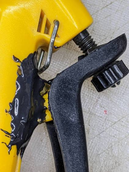
Garden Sprayer – pivot repair
Buried under the epoxy is the flimsy tab with the pivot around which the handle moves. Any sideways force will did snap the tab off flush with the body. I had previously repaired it with solvent adhesive, so something more substantial seemed appropriate.
A closer look shows the edges of the brass flange I formed around the tab to absorb the stress:
Garden Sprayer – pivot repair – detail
It’s pretty much fully depreciated, but if I don’t use the epoxy it will go bad on the shelf, so …
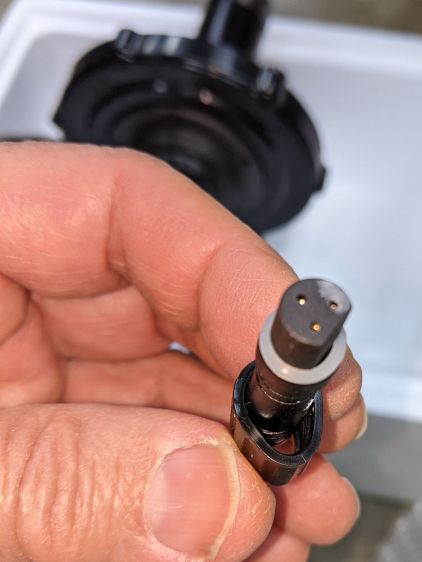
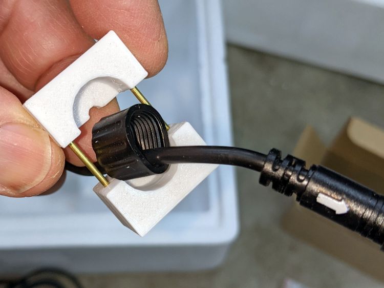
A Bafang BBS02 (for a friend’s upright bike) arrived with a deformed speed sensor nut:
Bafang BBS02 – Deformed speed sensor nut – end view
It traveled halfway around the planet while trapped underneath the motor and, if it rode in the top layer or two of containers, the combination of pressure and heat would be irresistible.
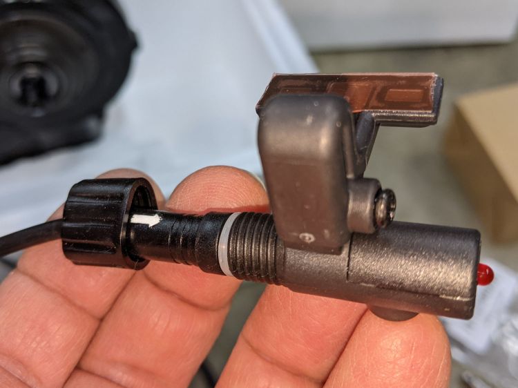
The plastic was stiff and I couldn’t force the nut over the connector using as much force as seemed reasonable:
Bafang BBS02 – Deformed speed sensor nut – test assembly
On the upside, the nut just compresses the silicone washer between the connector and the sensor to make a waterproof joint, so it need not have perfect threads or a uniform shape. Once the nut is in place, it will likely never be removed and should never bother anyone else.
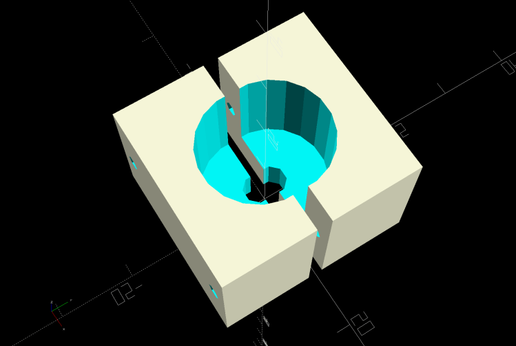
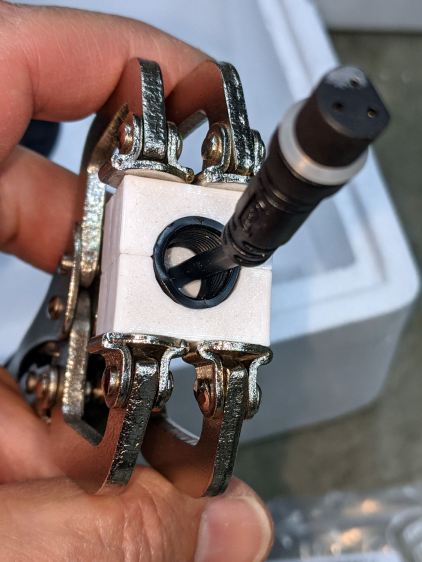
Being unwilling to apply a hot-air gun near the cable, I decided to try slowly cold-forming the nut inside a mold:
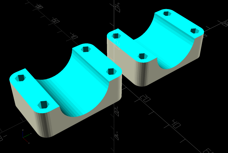
Sensor Nut mold – solid model
The gap isn’t a kerf: the two halves meet to form a cylindrical pocket. The smaller holes fit a pair of brass tubes keeping the halves lined up while I arrange things:
A few days of squashing made it round-er, whereupon I applied the clamp directly against the remaining high point with the other side cradled in the mold. It still doesn’t slide over the connector body, but I’m not in a rush.
Bafang tech support generously sent a speed sensor extension cable from which I can extract a good nut, which will require cutting and splicing the cable from the motor.
This is laid in against a need I hope never occurs:
Dripworks 0.75 inch pipe clamp
It’s intended to clamp around one of the Dripworks mainline pipes carrying water from the pressure regulator to the driplines in the raised beds, should an errant shovel or fork find the pipe.
It descends from a long line of soaker hoseclamps, with a 25 mm ID allowing for a silicone tape wrap as a water barrier.
This file contains hidden or bidirectional Unicode text that may be interpreted or compiled differently than what appears below. To review, open the file in an editor that reveals hidden Unicode characters.
Learn more about bidirectional Unicode characters
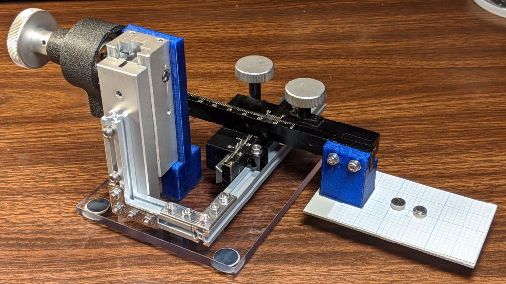
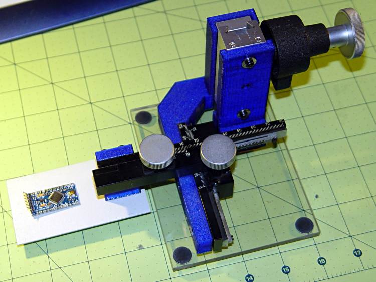
Protip: before dismantling a fitted slide, mark one end so you know how to put it back together. Bonus points for taking a picture:
Microscope Stage Positioner – slide marking
Double bonus points for writing a blog post.
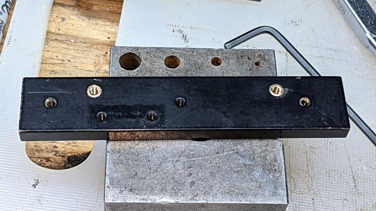
Rather than fight with the existing fine-pitch USA-ian screws, I drilled out their threaded holes:
Microscope Stage Positioner – Y slide drilling
And epoxied 3 mm brass inserts in their place:
Microscope Stage Positioner – Y slide M3 inserts
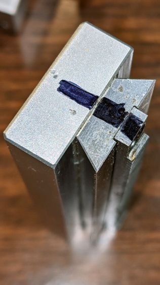
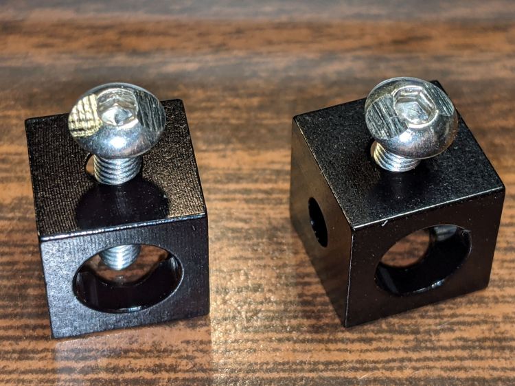
Those holes match up with a pair of corner cubes normally appearing on the end of the beams:
Microscope Stage Positioner – BHCS mods for Makerbeam
It turns out M3 button head cap screws will slide into the beams if you file the slightest angle on opposite sides of the button, although a small bag of tiny tee nuts should arrive in a while.
Then a variety of brackets spliced everything together:
Microscope Stage Positioner – Makerbeam detail
Although it looks strictly from industrial, it actually wasn’t much better than the plastic edition and, in fact, the beam supporting the XY slides sagged about the same 5 mm. The plastic upright post also contributed a bit of wobble.
It turns out that the extruded aluminum beams have plenty of longitudinal and torsional stiffness, but all those flat steel fittings don’t.
There’s a way to work with the beam strengths, rather than against them, but that’s a story for another day …
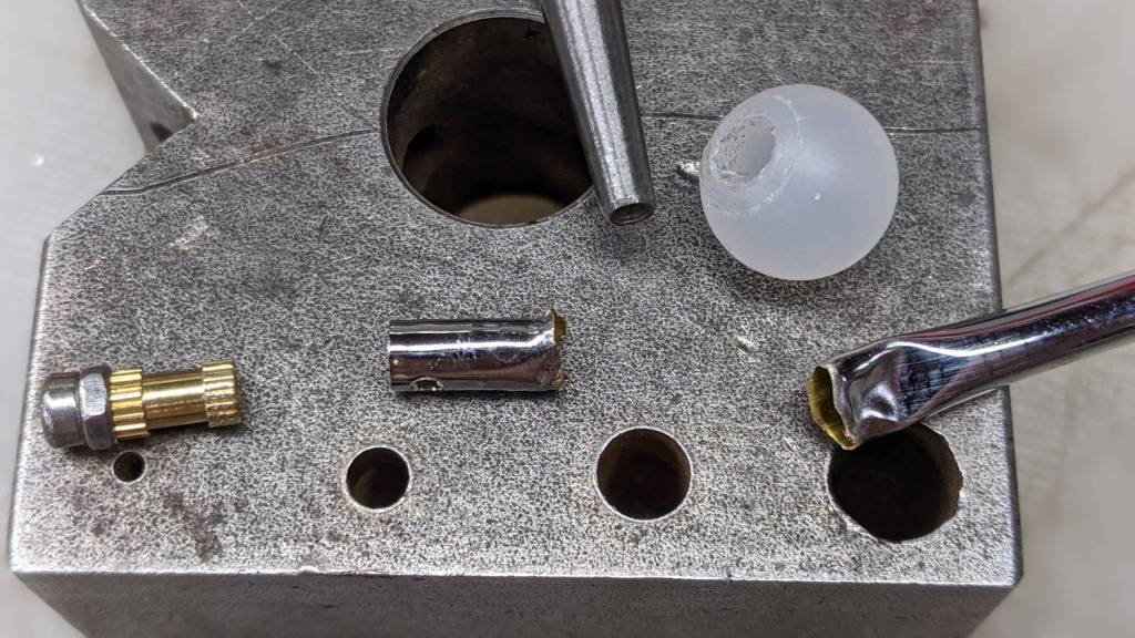
One of the good things about building your own stuff is that you have all the parts when something breaks:
Helmet Mirror – damaged parts
The decorative M2 screw and insert pulled out of the ball. The rim of the nail set punch (intruding from the top) just barely caught the edge of the stub inside the ball, so a few taps could extract it. A Dremel cutoff wheel peeled the crumpled end off the stalk.
Reassembly proceeded without incident:
Helmet Mirror – installed
The bizarrely blurred mirror over on the left comes from the Pixel phone camera app deciding this was a Portrait, applying a background blur, and running into trouble with those hard edges in the foreground. The camera app has a distinct Portrait mode that, perhaps, I inadvertently engaged while fumbling around.
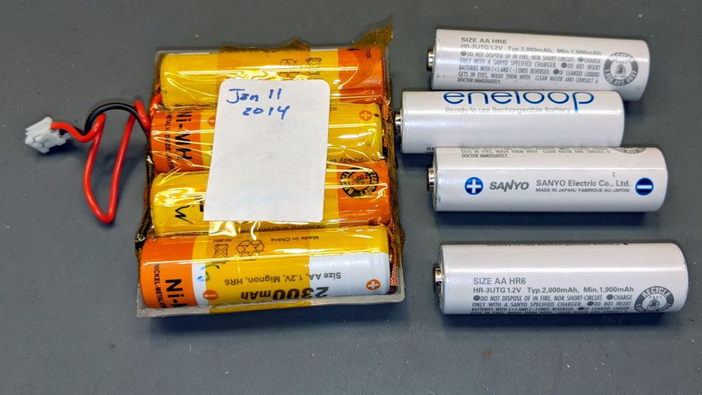
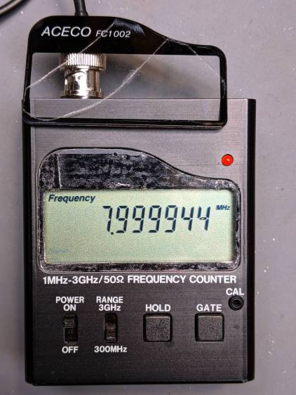
My old Aceco FC1002 frequency meter stopped working without being plugged into the charger. It runs from a quartet of NiMH cells taped into a tray I made seven years ago:
The faceplate bears the scars of its cracked acrylic (?) coating, so I pushed it out, traced the outline on a flat piece of polypropylene clamshell packaging, cut it out, and stuck it in place with tapeless sticky:
Aceco FC1002 – polypropylene faceplate
That removes the branding, but IMO improves the appearance.
It should continue working for another half decade or so!
We recently installed a Dripworks drip irrigation system for Mary’s garden and, of course, pre-assembled the emitter / dripline tubing, fittings, and supply / filter / plumbing for each of the beds in the Basement Shop. A few days after burying the main lines, plumbing the filter + pressure regulator, and plugging in half a dozen bed assemblies, Mary noticed some emitter tubes weren’t delivering any water and other beds seemed too dry.
N.B.: We bought everything directly from Dripworks. This is not counterfeit crap from a sketchy Amazon seller.
I cut the dripline just downstream of the Micro-Flowvalve on a completely dry bed, whereupon no water emerged. Cutting the supply tube just upstream of the valve produced a jet squirting halfway along the bed. I tried and failed to blow air through the valve: it was completely blocked despite being in the “open” position. I installed another valve and the emitter tube started working properly.
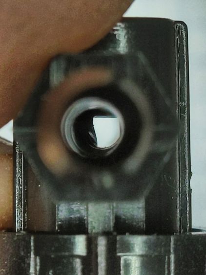
I sat down at the kitchen table with a bag of unused valves and peered through them (the pix are through the microscope):
Dripworks valve – mostly open lumen
That’s one of the better-looking valves, with only a little mold flash in the lumen.
Partially occluded lumens were more typical:
Dripworks valve – partially occluded lumen
Quite a few were almost completely obstructed:
Dripworks valve – mostly occluded lumen
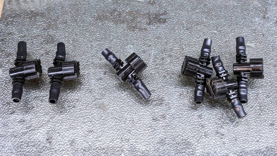
For lack of better instrumentation, I blew through the valves and sorted them by effort:
Dripworks valve – sorted by blockage
Two of the valves in the group on the left are completely blocked, with the others mostly blocked.
The middle group has enough mold flash to produce noticeable resistance to the air flow. I think water would have more trouble getting through, but the emitters would at least look like they’re delivering water.
The group on the right has mostly unblocked valves, with visible mold flash but little restriction.
I have no way to measure the actual water flow, so it’s entirely possible the QC spec allows considerable blockage while still delivering enough water to the emitters. More likely, the spec assumes a clear lumen and the mold flash is a total QC faceplant; it’s obviously not a controlled quantity.
Well, I can fix that:
Dripworks valve – drilling
That’s a 2.3 mm drill going straight through the valve body. I drilled the valves from both ends and blew out the swarf:
Dripworks valve – drill swarf
That produced twenty valves with clear lumens. Of course, the drill leaves a slightly rough interior surface, but it’s now much easier to blow air through them.
We hadn’t installed the driplines in two beds with three emitter tubes per bed. I cut out those six unused valves and sorted them by resistance:
Dripworks valve – six samples
Both of the valves on the left are blocked, the three on the right are mostly OK, and the one in the middle is partially blocked.
With two dozen repaired valves in hand, we returned to the garden, I cut 22 valves out of the installed driplines and replaced them under field conditions. Returning to the Basement Laboratory, I blew the water out (*), sorted them by resistance, and produced a similar distribution, albeit with no pictorial evidence. Although we have no immediate need for the used valves, they’re drilled out and ready for use.
In very round numbers, you should expect:
A third of Dripworks valves will pass (close to) the expected flow
A third will have a minor flow restriction
A quarter will have a severe flow restriction
One valve in ten will be completely blocked
Plan to drill out all the Micro-Flow valves before you assemble your driplines.
AFAICT, none of the other ¼ inch fittings we used have any interior flash, so it’s only a problem with the valves.