
The Samsung over-the-range microwave (ME18H704SFS, should you care) that Came With The House™ coughed up a C-11 error code resolving to “replace the gas / humidity sensor”. Replacement DE32-60013A sensors are readily available, although if you’re expecting a Genuine Samsung Part from Amazon, that is not the universe I live in.
You can remove the upper front bezel from the microwave to reveal the slotted front cover of the compartment containing the sensor, but you cannot replace the sensor without extracting the microwave from above the stove and removing its shell. The bottom of the microwave sits about 18 inches above the stove, so I put a 16 inch cubical moving box (of which we have a near-infinite supply) on the stove to reduce the risk of dropping the mumble thing while removing it.
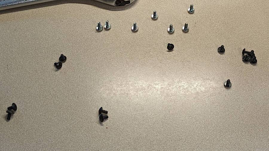
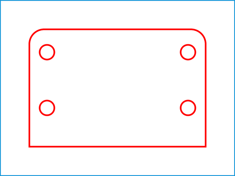
A total of 20 screws, here laid out in roughly geographic order, hold the shell to the inner frame:
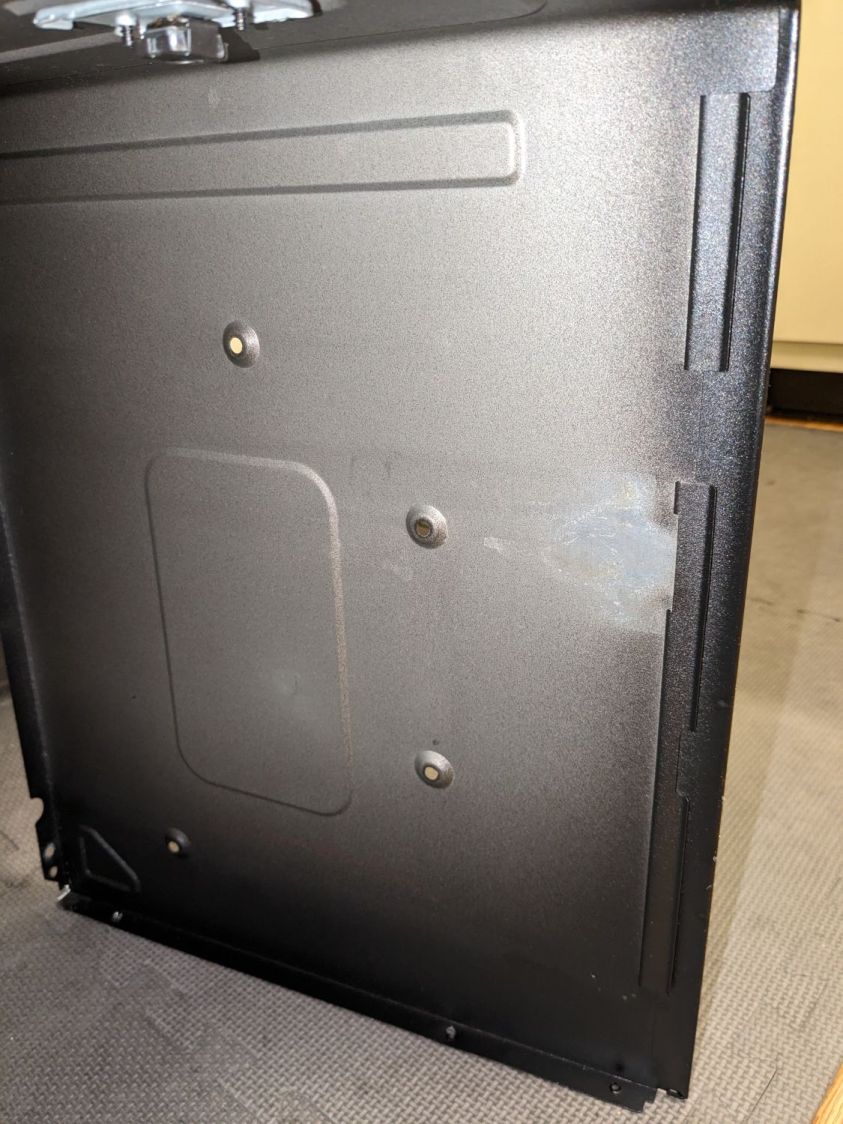
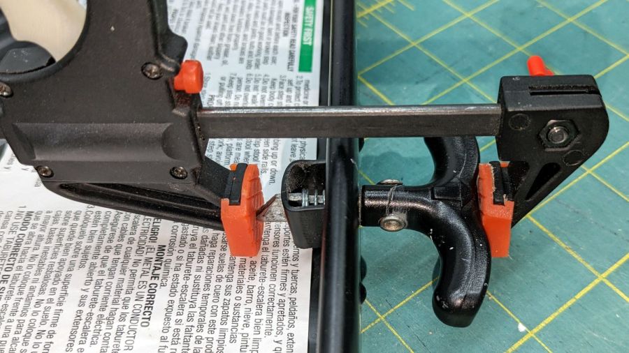
With all the screws out, slide the shell toward the rear by more than you might think to clear the latches along both sides. The latches along the front of the right side look like this:
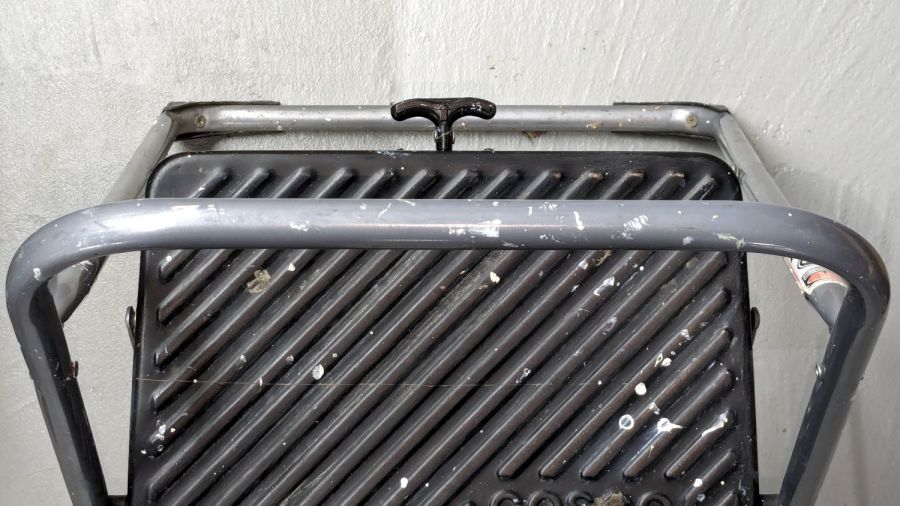
With the shell off, the sensor compartment on the top of the microwave enclosure is revealed:
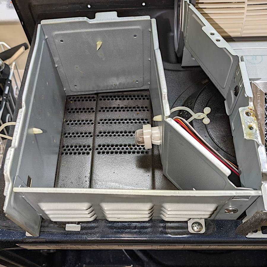
Although you might think removing those two screws would grant access to the sensor compartment and let you replace the sensor (if you have very long fingers), that is not the case: the small tab toward the left side of the louvered front plate prevents you from sliding it and the plate is not hinged along its left side.
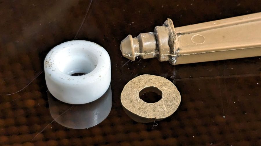
The sensor is held into the socket by a clip snapping into the arms that, in turn, hold the socket into the side wall:

A small screwdriver will assist in releasing the latches on the clip arms; squeezing them in the obvious way didn’t get the job done.
The old sensor then unplugs and the new one plugs in the obvious manner; it is not polarized and either orientation works.
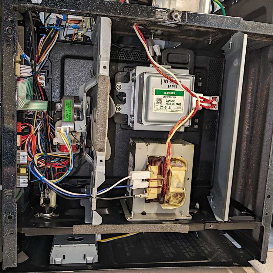
For completeness, the top of the electronics bay:
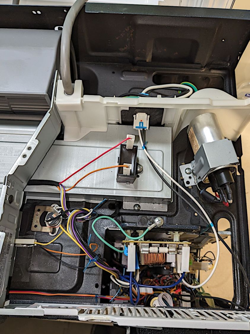
The magnetron and HV transformer live on the right side:
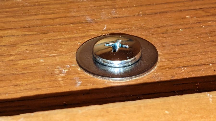
Then you reassemble in reverse order, heave the microwave atop the 16 inch cubical box, hoist it onto the rail along the back, and install the two loooong screws from the top while holding the front upward with one knee. I took the liberty of replacing the janky steel plates pretending to be washers with actual fender washers:
And now it works the way it should.
Of course, the microwave’s “beverage” mode assumes you’re drinking a piddly 8 ounces, rather than sipping from a manly 20 ounce mug:
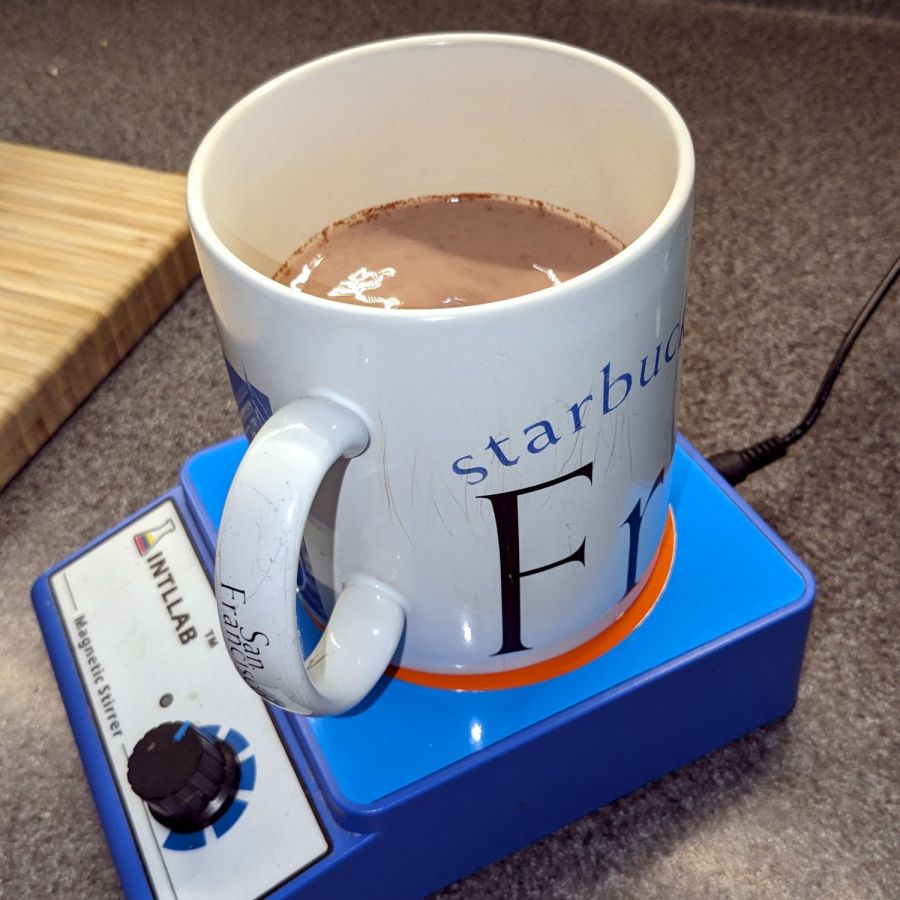
It heats 9 ounces of milk + cocoa just fine, but those 18 ounces of water for tea become just barely tepid.
WordPress has gone full-frontal AI and suggested I use this AI creation as the Featured Image:
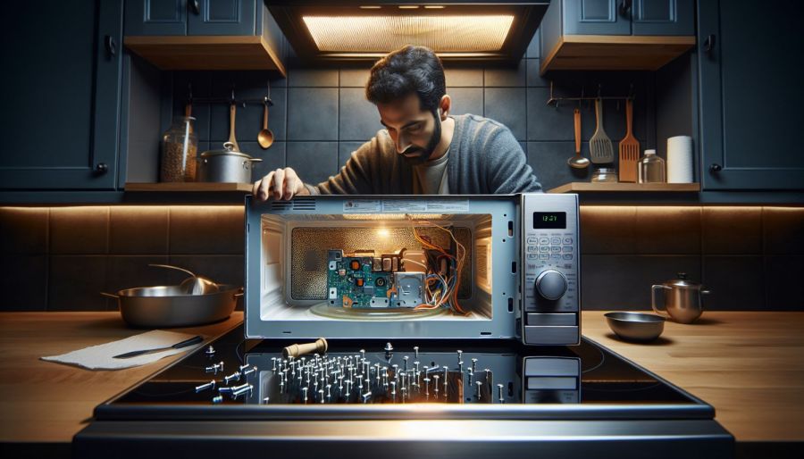
Inquiring minds want to know:
- Black tile in a kitchen makes sense because … ?
- Why does the doorless microwave have a knob?
- Who is that handsome guy?
- So. Many. Screws.
At least his hand has the right number of fingers, even if they do look a bit arthritic.
The WordPress AI generated this evaluation of my writing:
The content provides a detailed guide on replacing the gas/humidity sensor in a Samsung over-the-range microwave. Consider adding subheadings to break down the process for easier reading. Additionally, including a brief introduction and a conclusion summarizing the key points would enhance the post. The technical details and images greatly support the instructions. Great job!
Dopamine rush in full effect!


