My brother-in-law Tee dropped his Sony DSC-H1 camera, which landed atop its shutter button on the pavement.
Bad news…
- the shutter button broke off
- the bezel popped out
- the teeny little snap ring that held the shutter button stem in the bezel vanished, because…
- the stem broke and the end vanished, too
Good news…
- apart from some scuffs, the camera still works
- he managed to find the shutter button
- and the button bezel
- and the spring!

A bit of browsing reveals that many, many Sony DSC-Hx (where x is an integer from 1 through 9, inclusive) owners have the same problem, minus the inconvenience & embarrassment of first dropping the camera. Turns out that the shutter button stem breaks at that notch in normal use.
It seems the stem snaps while you’re taking pix, whereupon the spring launches itself and the button cap into the nearest river / drain grate / weedy area, never to be seen again. Tee is exceedingly fortunate to have found all the major pieces!

Here’s the broken end of the stem, with the button cap out of focus in the background. The stem is 1.5 mm in diameter, so the snap ring was surrounding, what, 0.75 mm of plastic? In what alternate universe did this design decision make sense?
I think the snap ring contributed to the problem by eroding the stem in the notch; that little white stub isn’t half of the stem diameter; it may have stretched under impact, but surely not all that much.
Yes, you can buy a replacement button for about 30 bucks direct from Sony, but it seems the new stem is subject to the same failure after a short while. They’re standing by the original design, marginal though it may be.
Now, obviously, this stem failed from abuse, no argument there. Everybody else had their stem fail without provocation, though, so it really isn’t adequate to the task at hand.

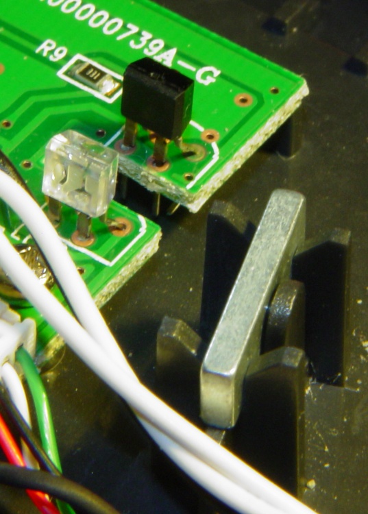
Anyhow, there’s also some damage at the bezel socket on the camera body, but nothing major. The dented silver areas on either side of the switch membrane are ESD shields, so that any static discharge from your finger will (most likely) dissipate on the external frame of the camera, rather than burrow into its guts via the switch.
The bezel twist-locks into the camera body, which means that you can remove the bezel if you can get a good grip on it. It turns clockwise to remove.

Peering closer at the membrane switch, it looks as though the button stem did some damage on its way out, although Tee admits to using various pointy objects to trigger the shutter while figuring out what to do with the camera.
More good news: the switch still works correctly, including the focus function with the button half-pressed, That means the switch membrane and contacts are in good shape.

The bezel itself is pretty well graunched, with a nest of cracks underneath that damaged arc to the left of the pictures. I think it’s in good enough condition that I can remove the bent plastic, ooze some solvent adhesive into the damage, and compress it enough to make everything stick together.

Obviously, this calls for some Quality Shop Time!
The overall plan is to remove the remaining stem from the button, drill-and-tap the button head for a miniature brass screw (1-72, I think), reshape the screw head into a membrane-friendly plunger (about 3 mm diameter and flat), then put it all back together with a nut in place of the snap ring.
I should be able to install the bezel (without the button), then insert some drill rod through the hole to figure out how far the screw must protrude to trigger the focus & shutter switches. Perhaps a pin vise will grip the drill rod and bottom out on the bezel’s central ring, so I can do a trial-and-error fitting?
Then I can adjust the screw to that overall length below the bezel with the button pressed, whack off anything that sticks out above the button, adjust the nut to limit the button’s outward travel, slobber Loctite over everything, and put it all together for the last time.
That’s the plan, anyway. As the Yiddish proverb has it, “If you wish to hear G*d laugh, tell him your plans.”
Some useful dimensions…

The rest of the story…