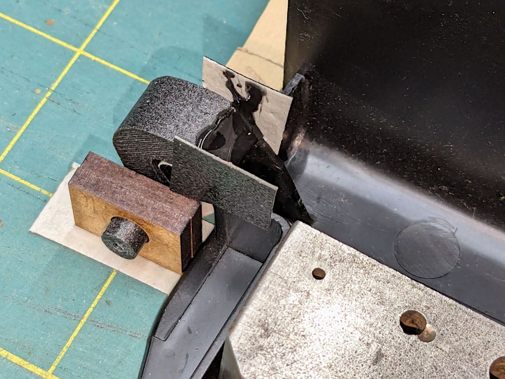
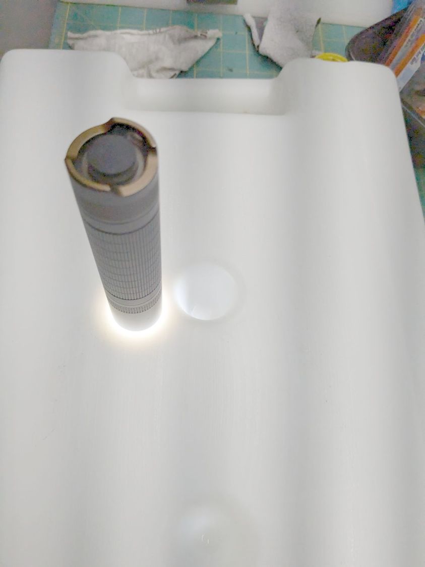
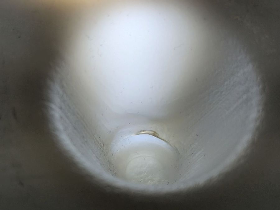
Although the Sears humidifier (Model 758.154200 if you’re keeping score) that Came With The House™ works fine with its lid hinges broken, Mary heard an odd hissing sound somewhere inside. The sound continued with the thing unplugged and, after a protracted struggle in the kitchen sink, we tracked the sound to a crack in one of the dimples joining the front and back faces of the right-side water bottle:
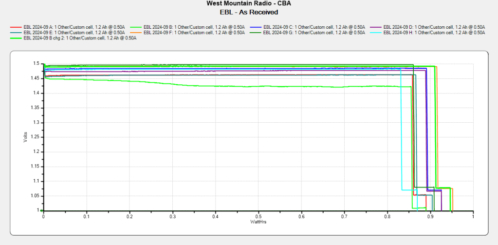
The vertical shaded bars come from the camera’s electronic shutter vs. unfiltered 60 Hz AC powering the shop LED lights.
Unsurprisingly, replacement bottles are no longer available, although you can get fill caps and valves, plus wicking filters.
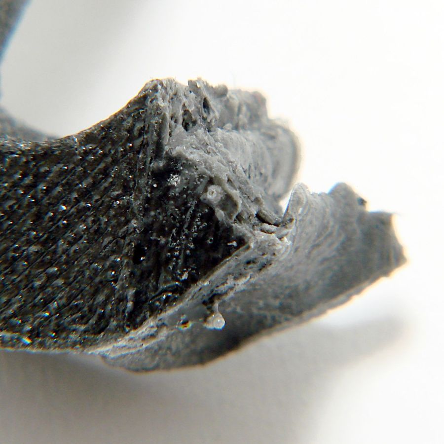
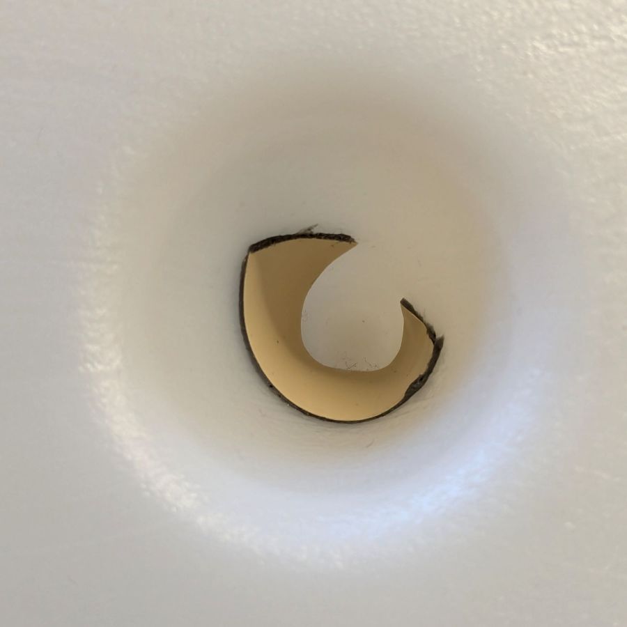
A water drop squeezed in the crack:
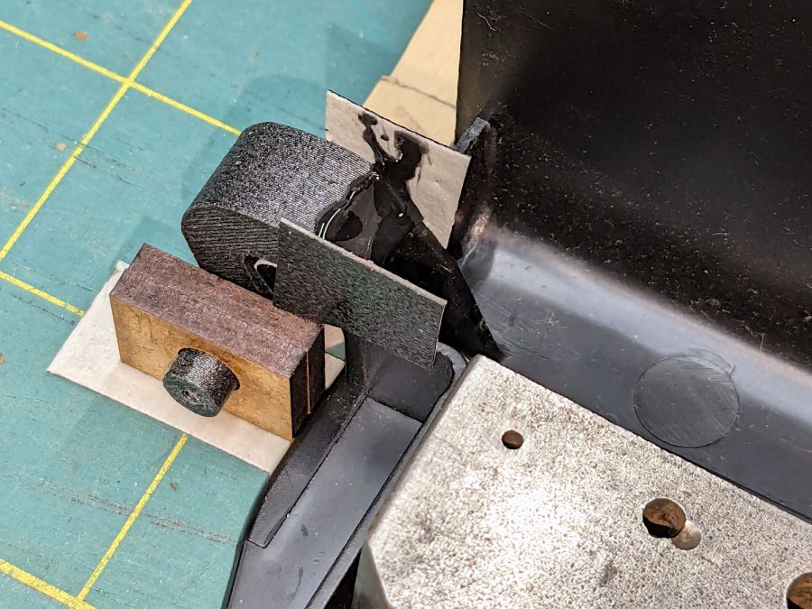
The bottles are polyethylene that sneers at any normal sealant, but I have a few square inches of tape intended for repairs exposed to weather. I didn’t get the snippet aligned just as I wanted, but its gooey adhesive definitely covered the crack:
The bottles normally operate with a slight vacuum, thus the air hissing through the crack, so the tape need not withstand any continuous pressure and the adhesive layer should flow into the crack if it goes anywhere at all.
Protip: the gooey adhesive bonds instantly and irrevocably to whatever it touches, so do a trial fit before you peel off the backing tape.
If the “Serial” is a date code, it’s been around for while:
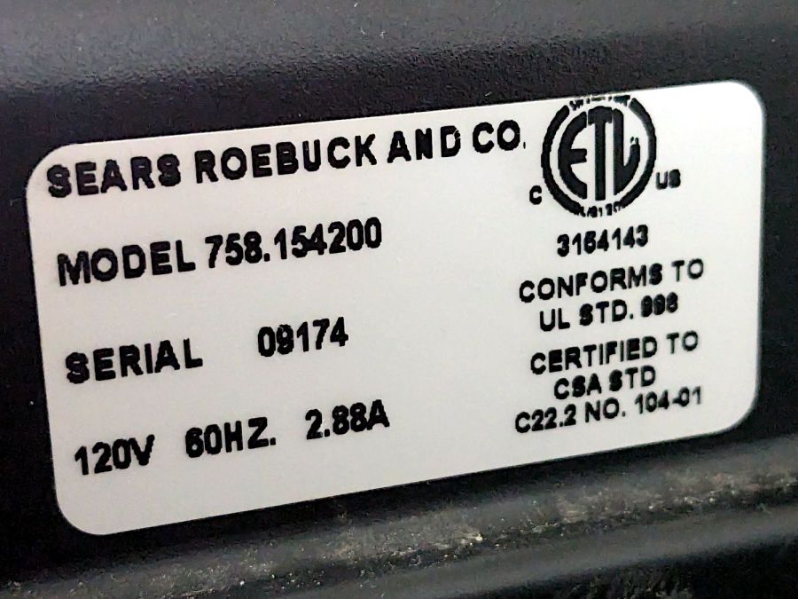
It should be good for a few more decades …