Ed Nisley's Blog: Shop notes, electronics, firmware, machinery, 3D printing, laser cuttery, and curiosities. Contents: 100% human thinking, 0% AI slop.
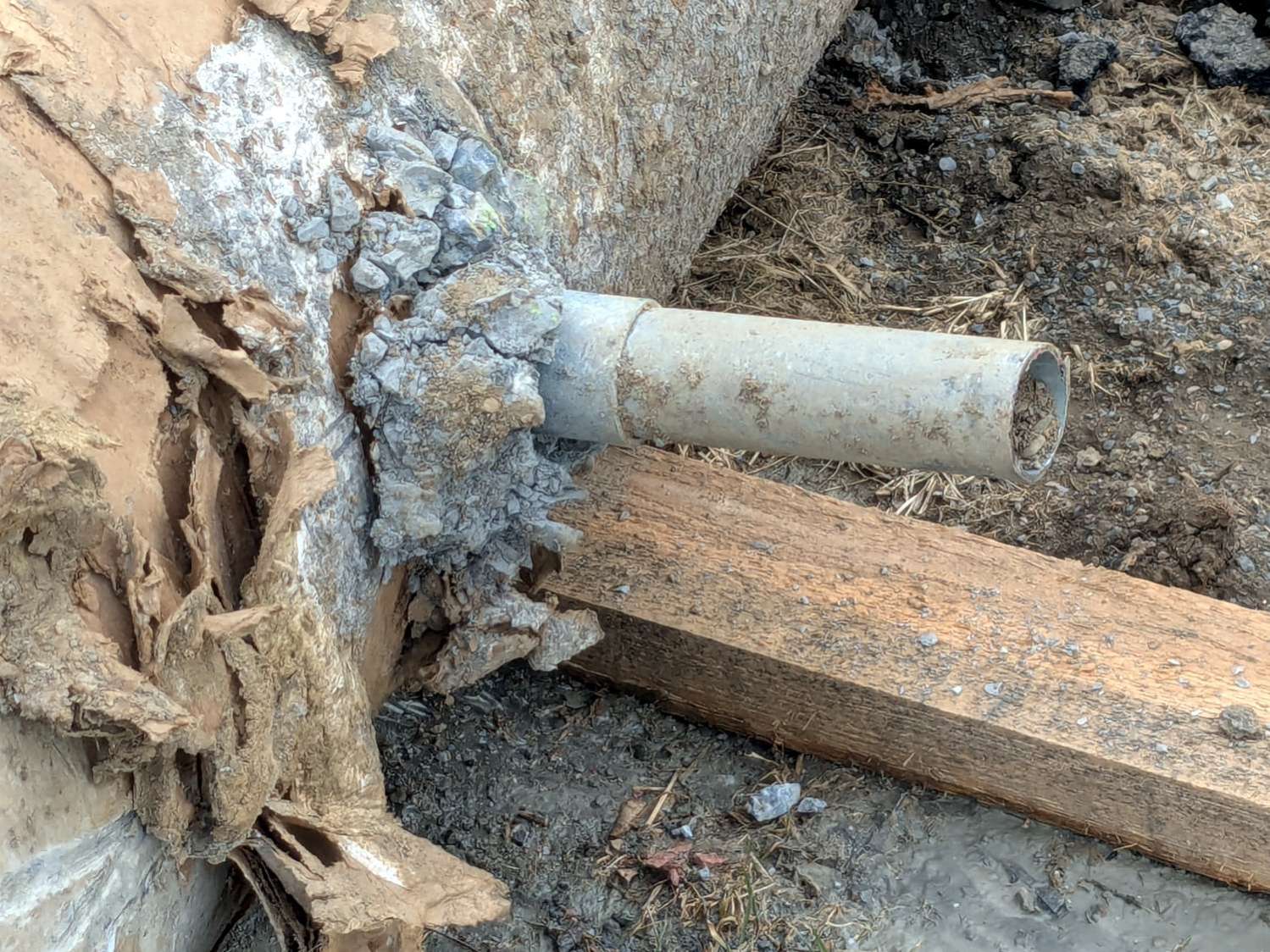
Apparently they excavated around the smashed bases and sawed off the conduits:
Street Lamp Base – sawed conduit
Then they yoinked the concrete cylinders, installed new bases, re-connected the conduits, cast more concrete, and installed the posts:
Street Lamp Base – Rombout House Ln – detail
I think the two “Signal” box covers flush with the surface on either side of Rombout House Lane lie just beyond the edges of what will eventually be the repaved road at the intersection.
Street Lamp Base – Rombout House Ln – overview
Given how much damage the base at that intersection encountered, my visualization of the Cosmic All says that pole will not survive the year unless they install a few well-spaced bollards.
There’s another pole on the other side of the road I expect will have a full-on collision, too.
Having devoted considerable effort to smoothing the HQ Sixteen’s path across the table, with commensurate improvement, Mary reported the machine suddenly developed a severe hitch in its left-to-right git-along. Given that she is moving fifty pounds of machine with fingertip pressure, anything interrupting its progress is a problem.
We found a spot where the machine abruptly and repeatably stopped rolling, but none of the four wheels had a visible problem and both tracks were smooth. The stitch regulator wheel sat directly above a table surface joint on the track base, but lifting it didn’t change the glitch. Rolling the machine while lifting the rear wheels off the track, which is significantly more difficult than it may seem, still encountered the bump.
Rolling while lifting the front wheels went smoothly, so something was wrong with one of the front wheels. I put the machine back at the worst spot, marked the bottom of both wheel rims, lifted-and-rotated the left wheel half a turn, and found the glitch happened with the right wheel’s mark downward.
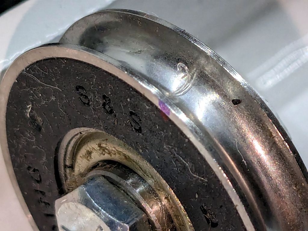
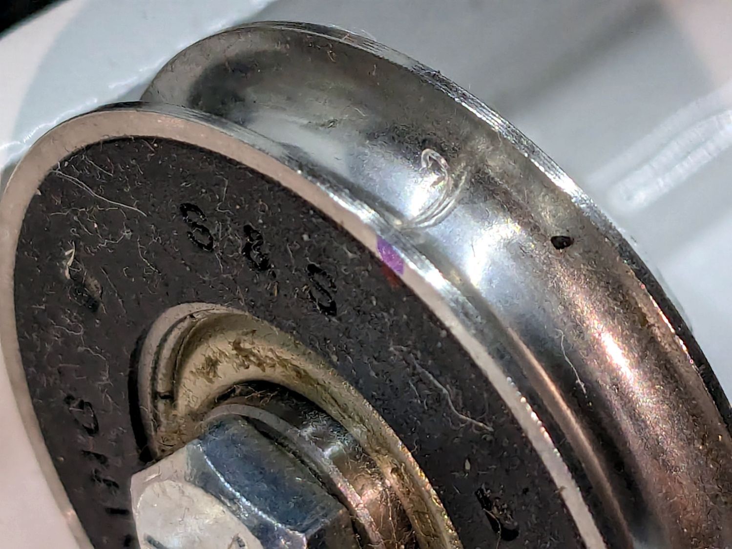
I lifted the machine off the carriage, took the carriage to the Basement Shop, and discovered what we could not see in situ:
HQ Sixteen – wheel crud – detail
For scale, the wheels are 8 mm across the flanges.
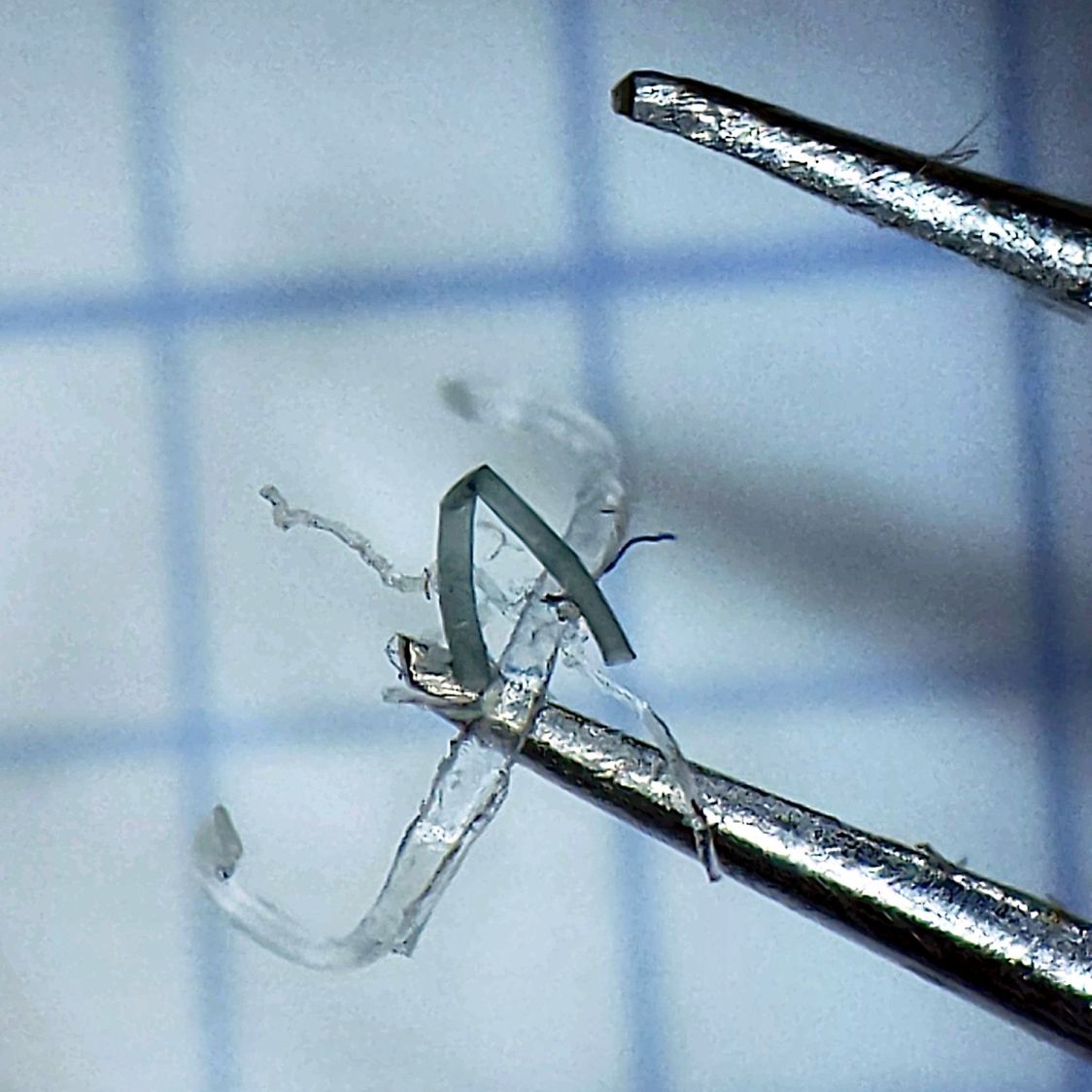
That thing looks like this up close:
HQ Sixteen – wheel crud – detail
The fibers were almost invisible in my palm as I carried it upstairs to show it off.
Apparently, a few millimeters of plastic fiber dropped from space directly onto the track and got mashed into the wheel as it rolled along. Given the vast expanses of fabric & batting going into projects on a long-arm sewing machine, that crud could have come from anywhere.
As we now realize just how much trouble can come from a tiny bit of crud, finding the next hitch in the git-along will be easier.
Quite by coincidence, a few days earlier a friend reported the speaker in her Ooma Telo2 had failed. This seems to be a common failure mode, with the rest of the gadget continuing to work fine.
The failed speaker showed continuity through its coil and, in fact, still had the same 8 Ω DC resistance as an identical speaker pulled from the Drawer o’ Small Speakers. It did not, however, make a sound when connected to a signal generator, where the new speaker squeaked happily.
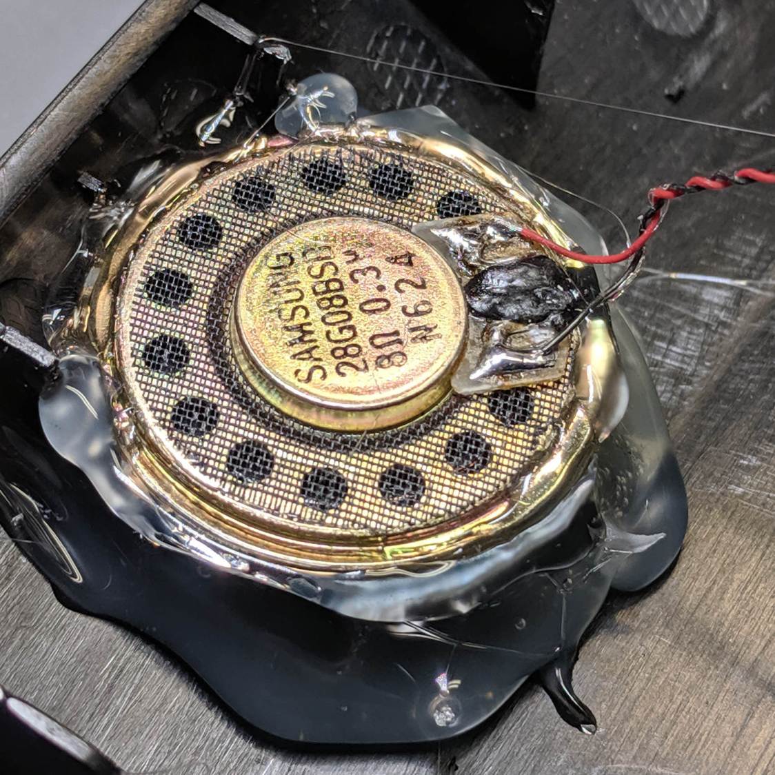
So it seems the speaker failed by a mechanical jam, rather than an electrical / wiring failure. It’s not as though we play thrash metal music through the thing, but apparently the magnet disintegrated:
Samsung speaker magnet disintegration
Yes, the coil gap is full of nicely oriented magnetic particles:
Samsung speaker magnet disintegration – detail
If Samsung (or whoever built the speaker) used a poorly sealed neodymium magnet, then it would crumble exactly as shown.
I wonder if that’s how the original speaker failed.
Installing the identical replacement speaker involved more hot melt glue and, as expected, restored the Telo2 to normal operation:
Trying out the Track Lock Blocks brought a long-standing puzzle to the surface: the left front wheel rode about a millimeter above its track, with the other three wheels carrying the weight of the machine. Neither that wheel nor the diagonally opposite wheel on the right rear worked well with the Blocks, because the machine rocked on the other two wheels.
I initially thought the carriage rail under the machine was warped, but some poking and prodding showed the left front wheel rode higher than the others from front to back across the entire length of the table.
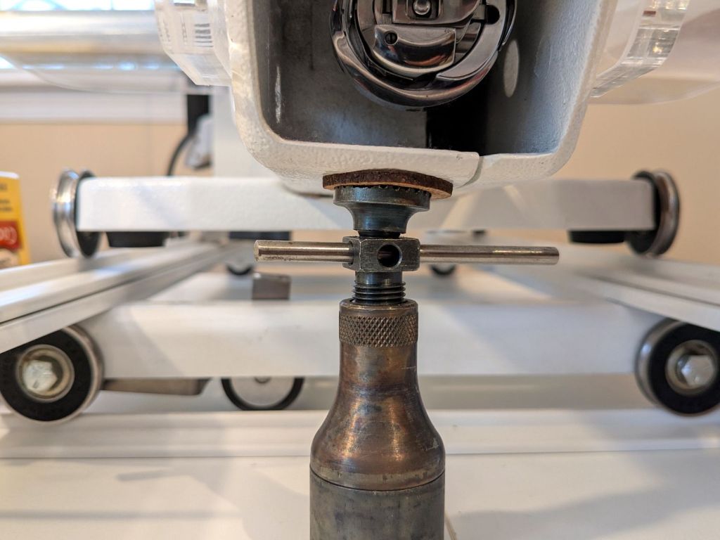
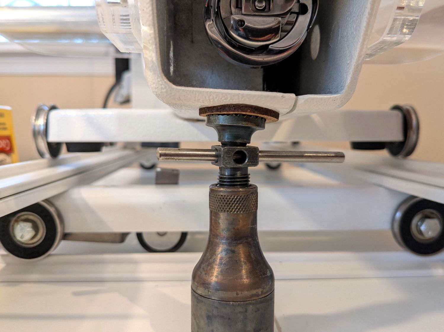
So I loosened the screws holding the front wheel base plate to the machine and jacked up the front of the machine to get the wheels off their tracks:
HQ Sixteen – track lock – jacking machine
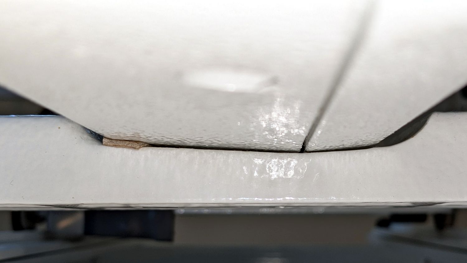
Then I jammed two strips of chipboard into the left side of the gap:
HQ Sixteen – front wheel base plate shim
I planned to use one long strip across the entire wheel base plate, but the screw holding the machine casting to the plate blocks the way, so it now has two shorter strips. Tightening the screws clamped the chipboard in place.
The chipboard tilted the base plate and lowered the left wheel, with the right wheel surely moving slightly upward. Lowering the machine showed both front wheels now carry roughly the same load and the Track Lock Blocks now work the way I expected.
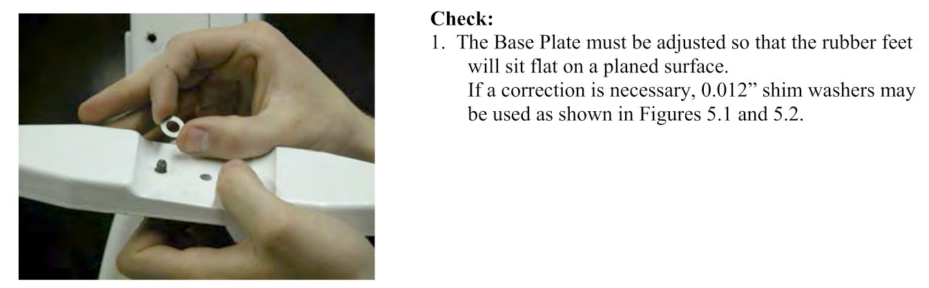
The only “planed surface” around here is on the surface plate in the Basement Shop, two flights of stairs away, and I am not carrying either object to meet the other.
In any event, I think the chipboard serves the same purpose as a simple washer, with advantage of a much larger bearing surface, so I’ll call it Good Enough until something else causes me to take the wheel base plate off.
Over the past year, the ancient WordPress theme I use for this blog has gradually stopped working, to the extent that some of you cannot enter comments and the GitHub Gists no longer display properly.
The ↓ (“down”) button on one of our lift chairs stopped working, although the ↑ (“up”) button worked fine and, as you’d expect, verifying this problem left the chair in a rather awkward position.
The usual power cycle and unplugging / replugging the control had no effect.
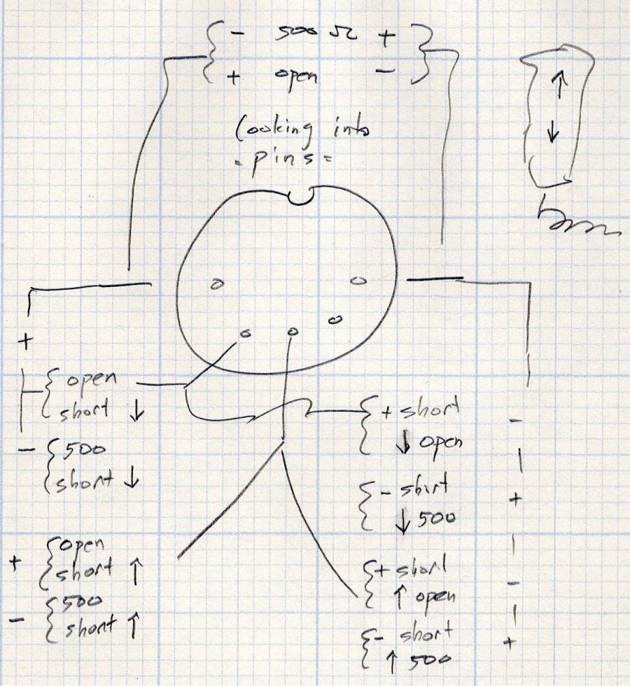
This control is the one I couldn’t pry apart to dim its LEDs, so I tried various combinations of pins until this scribble emerged:
Pride Lift Chair – control pinout doodle
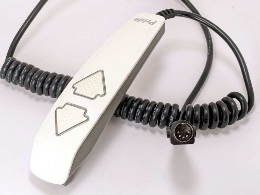
I have no idea of the correct pin numbering, but the scribble looks into the connector pins with the keyway on top:
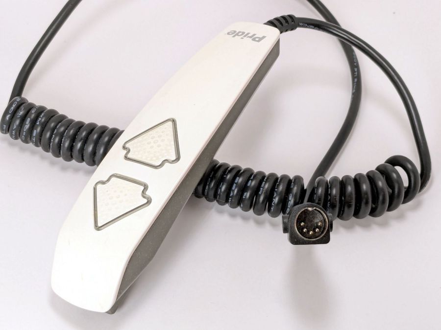
Pride lift chair control
The more intricate control for the other Pride lift chair has only four pins in its connector, so I couldn’t just swap them to see what happened.
The polarities are for the continuity / resistance test probes.
The takeaway: The two buttons did similar things to two different connector pins, so the control seemed to be working correctly and the fault lies elsewhere.
The control sports a USB jack for powering / charging your favorite device and I’m reasonably sure the control has a microcontroller tucked in there for good reason, implying the circuitry is surely more complex than maybe a rectifier bridge and some resistors.
So I shoved the chair into the middle of the room, deployed some test equipment, reconnected the control, plugged the chair power supply into the outlet strip, and … of course both buttons worked perfectly.
Soooo the chair is back in place and we’ll see what happens next.
Speaking of Heisenbugs, the HQ Sixteen continues to work fine, too.
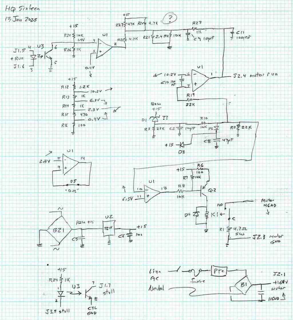
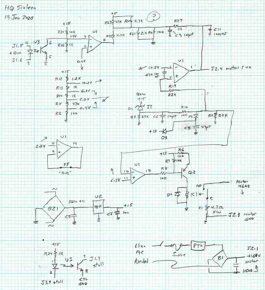
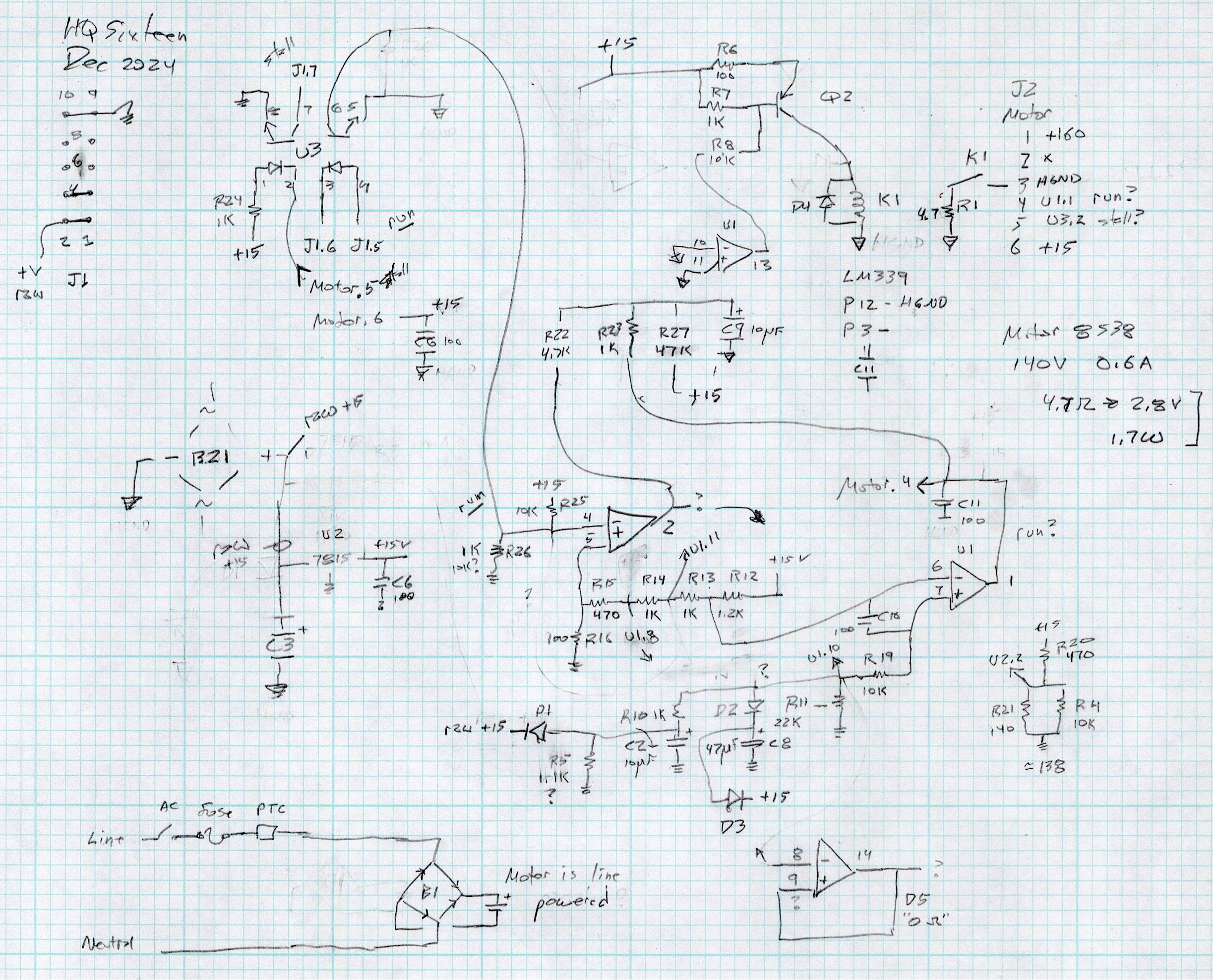
After running reliably for a few weeks, the HQ Sixteen Heisenbug returned, displaying a Motor Stall error on the first attempt to run the motor. This gave me the opportunity to extract the PCB, compare it with the first rough schematic, then correct a few resistor values and connections.
Do not assume any connections or components are correct or correctly drawn.
!!CAUTION!! The motor supply is direct-from-the-AC-line non-isolated +160 VDC.
!!CAUTION!! The GND traces are not isolated from the AC line and are not at the normal “0 V” AC neutral potential.
When the machine operates normally, the relay pulls in with a distinct click slightly after the power switch closed. With the Heisenbug in full effect, the relay does not click, suggesting a fault in its driver circuitry.
With the motor pod resting on a box beside the machine, I gingerly measured the voltage at various points on the top of the PCB. As far as I could tell, the entire +15 VDC power supply was dead: no voltage at either the input or output terminal of the LM7815 regulator!
NOTE: The obvious screws along the top edge of the PCB are not connected to the power PCB circuit GND. Instead, they’re part of the controller’s power circuitry from the isolated power supply produced by rectifier bridge B3 and passed through J1 in the upper left corner of the PCB. Instead, the left lead on R1 (the 5W sandbox resistor) is a convenient GND terminal.
So I hauled the little DSO150 battery-powered oscilloscope and a handful of clip leads up from the Basement Laboratory, got everything arranged, turned on the power, and the machine worked perfectly again.
That’s why it’s called a Heisenbug: look at it and it vanishes.
Given a faint indication of power supply problems, I verified all four diodes in Bridge Rectifier B21 are OK and the Skynet transformer windings were solid. I resoldered all the PCB connections from the transformer to U2, the LM7815 regulator, plus the green jumper wires.
The machine is now back together, it continues to work, and all my test equipment is back in the basement.
If it happens again, I’ll mount a cheerful LED on the pod to show the supply is working.


