Ed Nisley's Blog: Shop notes, electronics, firmware, machinery, 3D printing, laser cuttery, and curiosities. Contents: 100% human thinking, 0% AI slop.
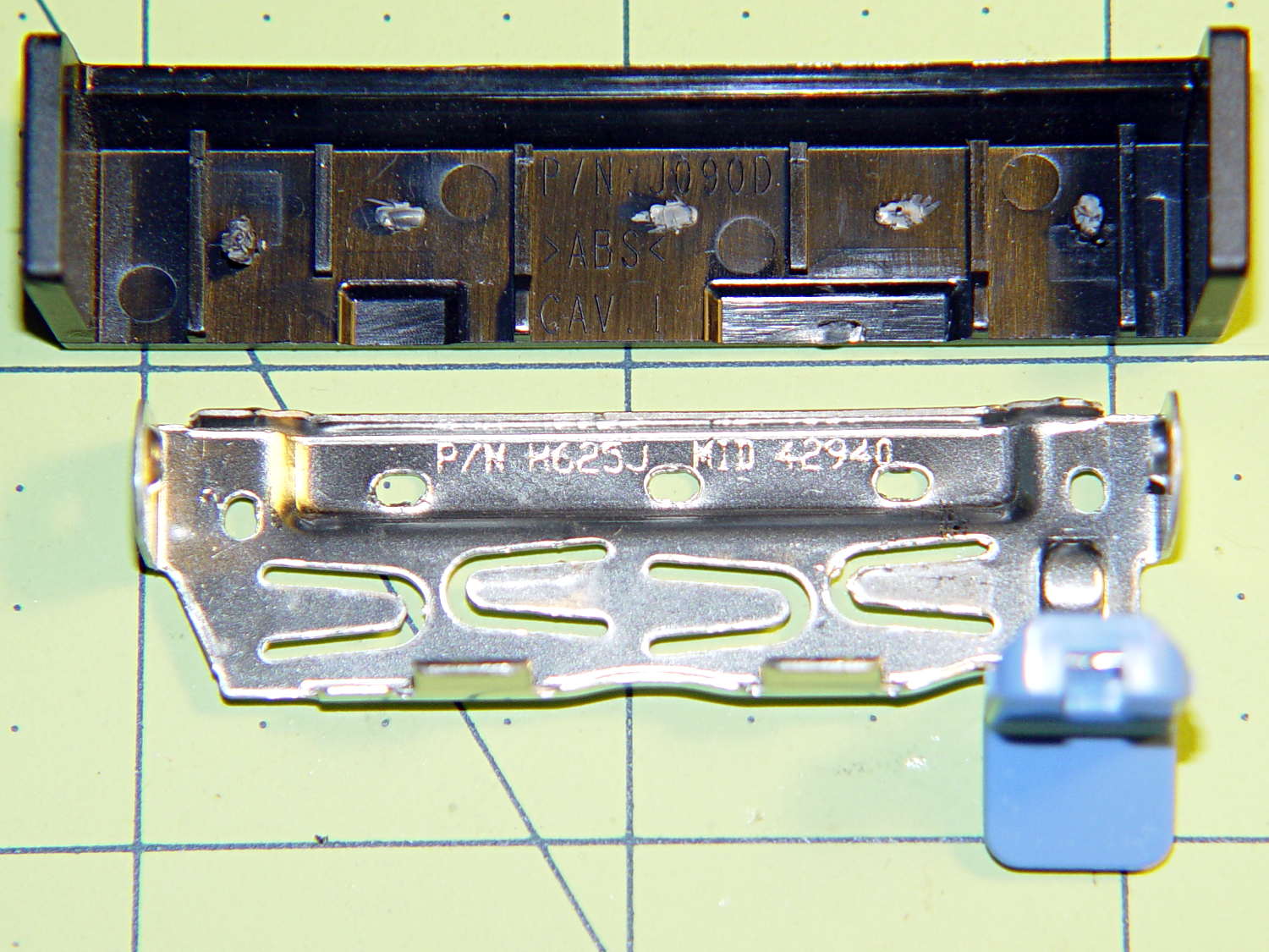
The new-to-me Optiplex 980 has a tool-free clamp securing the PCI card brackets to the chassis, with a nice plastic dress cover that really finishes off that side of the case. Alas, it’s secured by five small heat-staked plastic pegs that I managed to shear off as part of a finger fumble that you’ll recognize when it happens to you and which I need not further discuss:
Optiplex 980 PCI Clamp Cover – disassembled
So I drilled two slightly undersized holes for the tiniest screws in the Little Box o’ Tiny Screws:
Optiplex 980 PCI Clamp Cover – drilling
The two end plates sticking up are the only square parts of the cover, so that thing is actually clamped by the right-side plate and sheer will power. I ran the drill down 3 mm from the top of the post at the slowest manual jog speed from the Joggy Thing and I did not break through the top and did not hit that lathe bit under the cover.
The screw threads and a dab of epoxy hold them in place:
Optiplex 980 PCI Clamp Cover – tiny screws
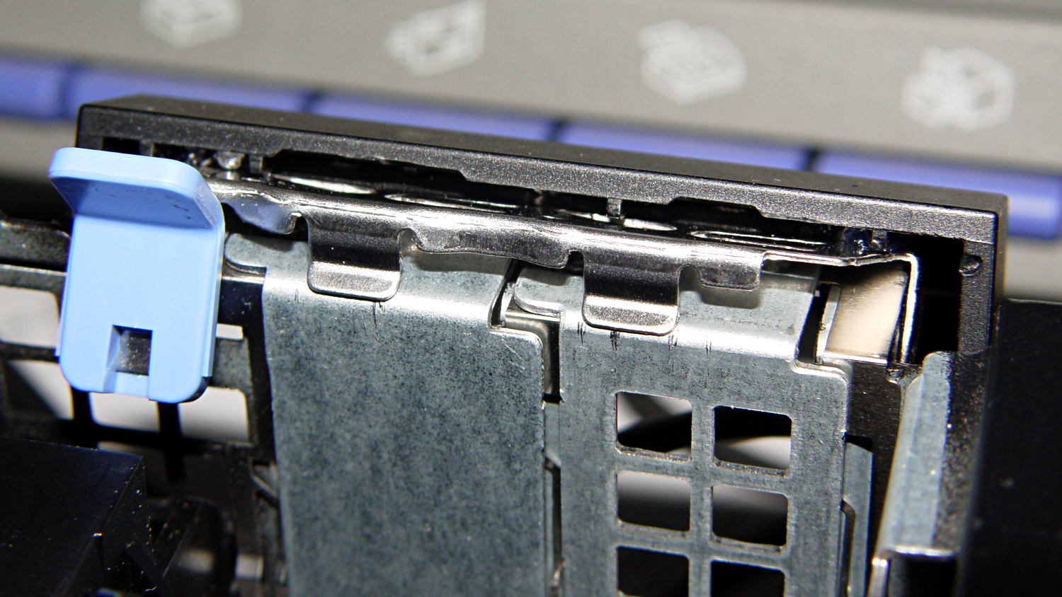
I’d like to say the finished repair looked like this:
Optiplex 980 PCI Clamp Cover – in place
But, alas, the eagle-eyed reader will note that the screws are gone, replaced by two dabs of clear acrylic caulk; those faint threads and epoxy were no match for the snap of that latching lever and the slight distortion caused by the spring fingers applying force to the brackets.
Although automobile batteries have “standard” sizes designated by BCI Group numbers, this Group 34R Sears Diehard battery was about an inch shorter than the previous one:
Toyota Sienna – short Group 34 battery
It arrived with a plastic grid embossed with the helpful notation “Use this height adapter under battery if necessary”, but I figured lower was better. A little bending, two snippets of mouse pad (remember mouse pads?), and a section of white plastic rod faced off / drilled on the lathe anchored it flat on the platform with no wiggle room at all.
With any luck, that’s the last battery the van will ever need…
Quick summary: the current Linux startup machinery Runs All The Things! in parallel, leaving you to figure out all the interdependencies and update all the script files to match your requirements. Mostly, the distro maintainers figure all that, but if you have essential files mounted as NFS shares, then you can will reach a login screen before the mount process completes.
Having wrestled with this problem for a while, I think I’ve doped out the right way to coerce the Upstart Pachinko Machine to converge on a workable login.
The solution is to fire off a unique signal after the NFS mount command, then force the display manager to wait until it receives that signal, rather than depend on happenstance as I did before. The mounts occur in /etc/init/local.conf, which now looks like this:
description "Stuff that should be in /etc/rc.local"
author "Ed Nisley - KE4ZNU"

start on (local-filesystems and net-device-up IFACE=em1)
stop on shutdown

emits nfs-mounted

script

logger Starting local init...

logger Mounting NFS filesystems
mount /mnt/bulkdata
mount /mnt/userfiles
mount /mnt/diskimages
mount /mnt/music
initctl emit nfs-mounted
logger Ending local init

end script
The start condition ensures that this code won’t run until the wired LAN is up; note that what was once eth0 is now em1. Then, after the mounts happen, initctl fires the nfs-mounted signal.
The modification to /etc/init/lightdm.conf script consists of one additional line to wait for that signal:
start on ((filesystem
           and runlevel [!06]
           and started dbus
           and plymouth-ready
           and nfs-mounted)
          or runlevel PREVLEVEL=S)

stop on runlevel [016]

emits login-session-start
emits desktop-session-start
emits desktop-shutdown
I’m not convinced lightdm.conf is the right spot to jam a stick in the gears, but it seems to be the least-awful alternative. The login-session-start signal doesn’t appear in any file in that subdirectory and I have no idea where else to look.
Anyhow, the greeter screen now shows a desktop background from the NFS mount, which I regard as A Good Sign:
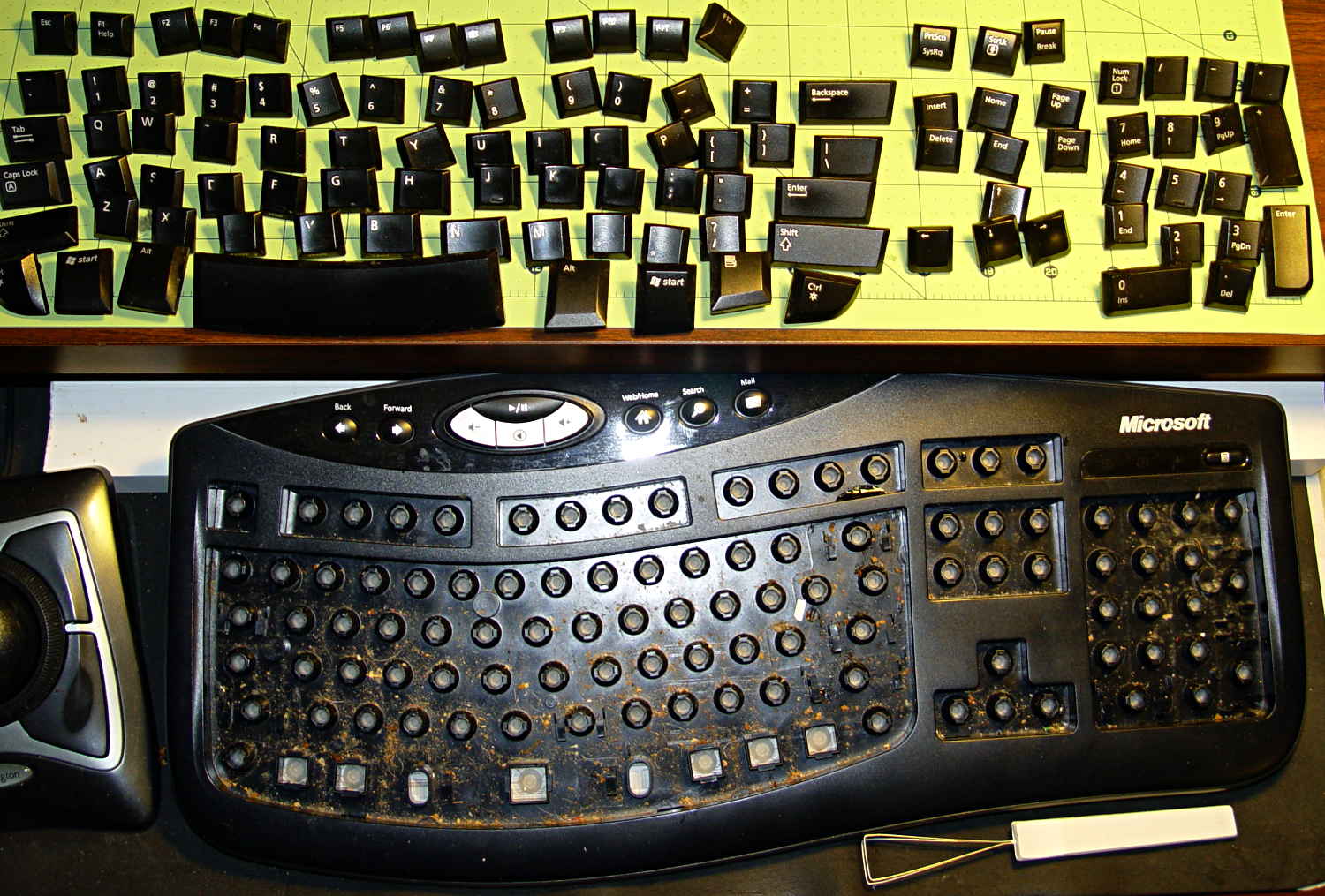
Part of the routine cleaning around here involves running the vacuum cleaner nozzle over the keyboard to suck up random debris, but that doesn’t extract crud from under the keycaps. Almost exactly three years after the previous cleaning, I finally decided the keys had lost enough of their normal feel to justify the hassle of taking the thing apart.
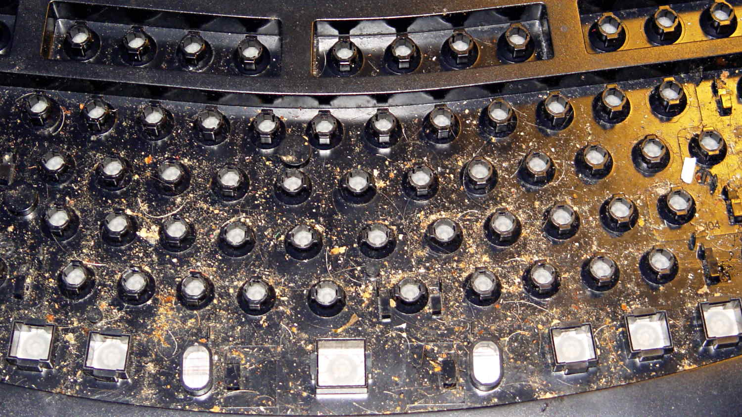
Bolstered by that experience, however, I just yanked the keycaps off with a removal tool from my old bag of tricks, revealing the horror that lies beneath the surface:
The keycaps took a swim in a dishpan full of hot soapy water, endured some scrubbing, and emerged looking like new. Thwacking them on a towel ejected the remaining water from the posts.
With the electronics still in place, I vacuumed the larger chunks out of the tray, scrubbed the aforementioned hot soapy water around the bushings with an acid brush, then cleaned up the residue with cotton swabs. There’s a paper towel under the drain gutters to catch the runoff, which worked surprisingly well.
The keycap legends have been eroding, as they’re basically a decal stuck on the surface. Eventually I’ll have a crappy non-clicky Das Keyboard Model S Ultimate.
[Update: a spammer’s script has been attempting to create hundreds of junk comments per day, so I’ve temporarily disabled comments for this post. Drop me a direct note using the About / Copyright / Contact link on the right if it’s critical. I expect this to pass in a few days, but I may be underestimating the stupidity out there. ]
A note from regular commenter Frans:
Don’t get a Das Keyboard if you want a keyboard without a keypad. Look into e.g. a Leopold Tenkeyless Otaku. The one to which I include a link comes with the same Cherry MX Brown switches as the Das Keyboard Silent.
The trio of batteries I built for the Sony DSC-F505V two years ago faded away; that camera seems particularly hard on the batteries, perhaps because they’re two cells in parallel that don’t share well. Two of the three seem pretty well gone:
Sony NP-FS11 2011 Packs – 2013-11 tests
Back then, I bought 12 cells, built six into those batteries, and left six charged cells sitting in a bag. After rebuilding the two worst batteries with those new-old-stock cells, it seems they maintained a substantial fraction of their charge while resting in the cool and the dark:
Sony NP-FS11 2011 Cells – 2013 packs – 2013-11-24
However, the camera would regard them as discharged, because it infers charge state from voltage. Squinting at the curves, their condition after a few minutes is roughly equal to a new & freshly charged battery produces over on the right when it’s nearly discharged.
The other curves show the result after their first charge in two years: basically, full capacity. The fact that both pairs of curves come pretty close to overlaying means they’re still well matched.
Sony NP-FS11 batteries – rebuilt
The third cell isn’t up to their spec, but it’s close enough to not bother rebuilding right now: 1.2 vs 1.4 A·h.
The Kapton tape pull tabs work wonderfully well, as the rebuilt batteries fit the compartment rather more snugly than the un-hacked cases.
Those simple floor brush strips for the Samsung vacuum cleaner worked moderately well, but the urethane adhesive didn’t have enough grip on the plastic strips. Having just run out of that batch, I made up another set with slightly undercut holes:
Bushing Solid Model – better holes – bottom
That’s half a thread width on each side, just enough to give the adhesive something to grab. Such is the plan, anyway.
I taped the strips to a pair of credit cards (actually, flat cards without embossed characters), slathered a thin layer of urethane atop them, and laid on squares of the same wool fabric I used the last time:
Samsung vacuum floor strips – gluing
Then I piled a steel block atop an aluminum slab on both arrays, fast forwarded a day, peeled and flexed and cut the strips apart:
Samsung floor brushes – glued
The urethane foamed through the holes as I hoped and (seems to have) locked the fabric in place, at least well enough to withstand some experimental bending on the workbench.
Now, to see how they stand up to actual use…
The OpenSCAD source code:
// Samsung Vacuum cleaner nozzle floor strips
// Ed Nisley KE4ZNU January 2013
//  November 2013 - adapt to M2, enlarge holes

Layout = "Build";			// Show, Build

//- Extrusion parameters must match reality!
//  Print with +0 shells and 3 solid layers

ThreadThick = 0.25;
ThreadWidth = 0.4;

HoleWindage = 0.75;

function IntegerMultiple(Size,Unit) = Unit * ceil(Size / Unit);

Protrusion = 0.1;           // make holes end cleanly

//----------------------
// Dimensions

Body = [6.0,59.0,3*ThreadThick];	// width, length, thick

Tab1 = [4.5,5.0,0.0];				// width, length, offset from centerline
Tab2 = [3.5,5.0,0.5];

HoleOC = 8.0;						// adhesive anchoring holes
HoleDia = 2.0;
HoleSides = 4;
HoleMax = floor(Body[1]/(2*HoleOC));

echo("HoleMax: ",HoleMax);

//----------------------
// Useful routines

module PolyCyl(Dia,Height,ForceSides=0) {           // based on nophead's polyholes

Sides = (ForceSides != 0) ? ForceSides : (ceil(Dia) + 2);

FixDia = Dia / cos(180/Sides);

cylinder(r=(FixDia + HoleWindage)/2,
         h=Height,
         $fn=Sides);
}

module ShowPegGrid(Space = 10.0,Size = 1.0) {

    Range = floor(50 / Space);

    for (x=[-Range:Range])
        for (y=[-Range:Range])
            translate([x*Space,y*Space,Size/2])
            %cube(Size,center=true);

}

module BackingStrip() {

	difference() {
		union() {
			translate([0,0,Body[2]/2])
			cube(Body,center=true);
			translate([Tab1[2],-1*Body[1]/2,Body[2]/2])
			cube([Tab1[0],2*Tab1[1],Body[2]],center=true);
			translate([Tab2[2],+1*Body[1]/2,Body[2]/2])
			cube([Tab2[0],2*Tab2[1],Body[2]],center=true);
		}
		for (i = [-HoleMax:HoleMax])
			translate([0,i*HoleOC,-Protrusion])
			rotate(45) {
				PolyCyl(HoleDia,(Body[2] + 2*Protrusion),HoleSides);
				PolyCyl((HoleDia + ThreadWidth),(ThreadThick + Protrusion),HoleSides);
			}
	}
}

//----------------------
// Build it!

ShowPegGrid();

if (Layout == "Show")
	BackingStrip();

if (Layout == "Build")
	rotate(90) BackingStrip();