The strut supporting the two drawers in the bottom of the refrigerator came out in two pieces during a recent cleaning session. To judge from the condition of the joint, I’d done this once before in its history:

That tab inserts into a slot in the front of the elaborate frame that supports the drawers, where it’s captured by a metal bar. Should you lift the rear of the strut without first removing the bar, the tab snaps off at the base. I’ve annotated the top of the strut in the hopes of reminding me the next time around.
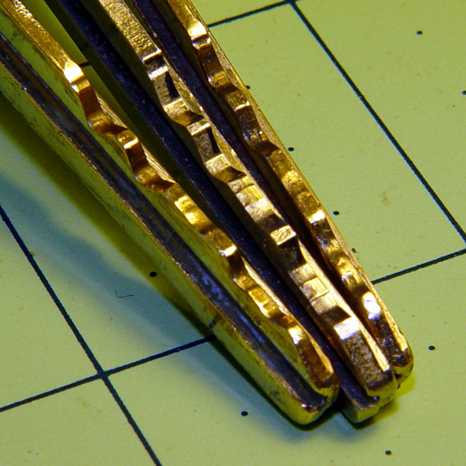
A pair of bumps at the front of the drawer guides should hold the drawers closed, but it’s pretty obvious that’s not working as intended:

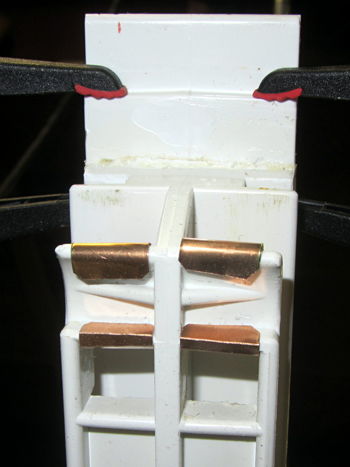
I shaped strips of phosphor bronze spring stock around the bumps:

The bottom view shows they’re held in place by crimps and a generous dollop of faith:
That should serve until I know whether the plastic drawer rail will carve through the metal. The drawers slide out with much more enthusiasm now, so it’s a Good Thing until something else breaks.
Yes, this is the refrigerator with the Freezer Dog…