Mary bought a pair of Revlon tweezers a while ago, picking a Name Brand to avoid hassles with bottom-dollar crap:

Well, that didn’t work.
I contend that the only difference between Name Brands and the bottom-dollar crap I tend to buy is a bit of QC and a lot of price. I’ll agree that’s not strictly true, but it does fit a goodly chunk of the observed data.
Anyhow.
I milled a recess into the corner of some scrap plastic to locate the handle end, then arranged a step block to capture the business end:

That setup ensures the holes go into the corresponding spots on both pieces, because I couldn’t figure out how to clamp them together and drill them both at once. I drilled the other piece with its good side up to align the holes; doing it bad side up would offset the holes if they’re not exactly along the center line.
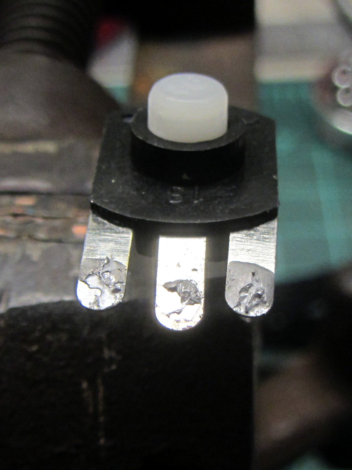
A closer look:

Talk about a precarious grip on the workpiece!
I filed the welds flat before drilling, so the pieces lay flat and didn’t distract the drill.
Then:
- Center-drill
- Drill 2-56 clearance
- Scuff up mating surfaces with coarse sandpaper
- Apply epoxy
- Insert screws
- Add Loctite
- Tighten nuts to a snug fit
- Align jaws
- Tighten nuts
- Fine-tune jaw alignment
- Apply mild clamping force to hold jaws together
- Wait overnight
- Saw screws and file flush
- Done!
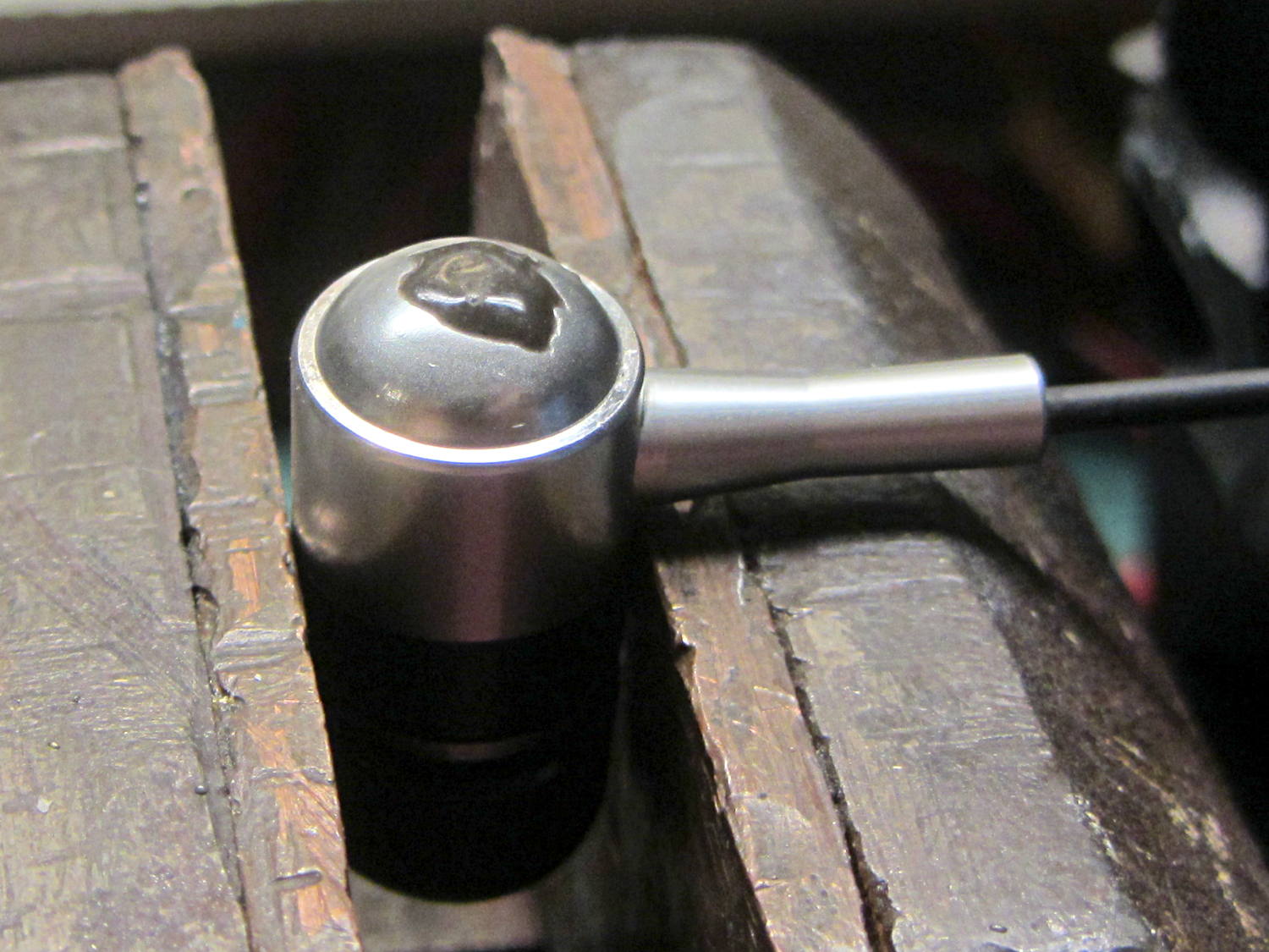
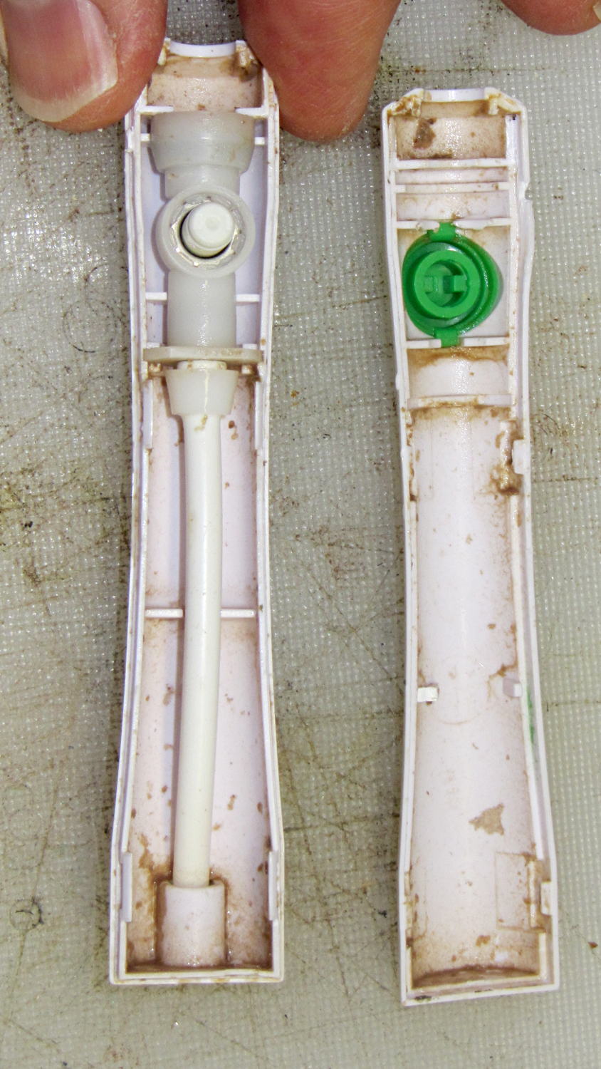
The clamping step:

Those nicely aligned and ground-to-fit jaws were the reason Mary bought this thing in the first place.
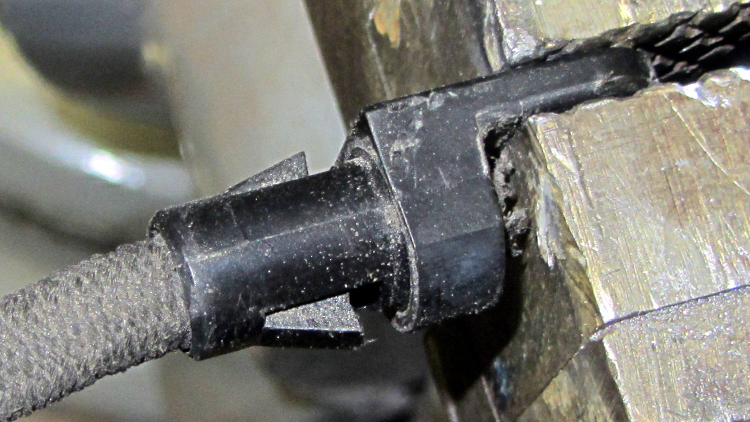
The screw heads look OK, in a techie sort of way:

The backside won’t win any awards:

But it won’t come apart ever again!
There’s surely a Revlon warranty covering manufacturing defects, printed on the long-discarded packaging, that requires mailing the parts with the original receipt back to some random address at our own expense.
Ptui!