Ed Nisley's Blog: Shop notes, electronics, firmware, machinery, 3D printing, laser cuttery, and curiosities. Contents: 100% human thinking, 0% AI slop.
Over the past year, the ancient WordPress theme I use for this blog has gradually stopped working, to the extent that some of you cannot enter comments and the GitHub Gists no longer display properly.
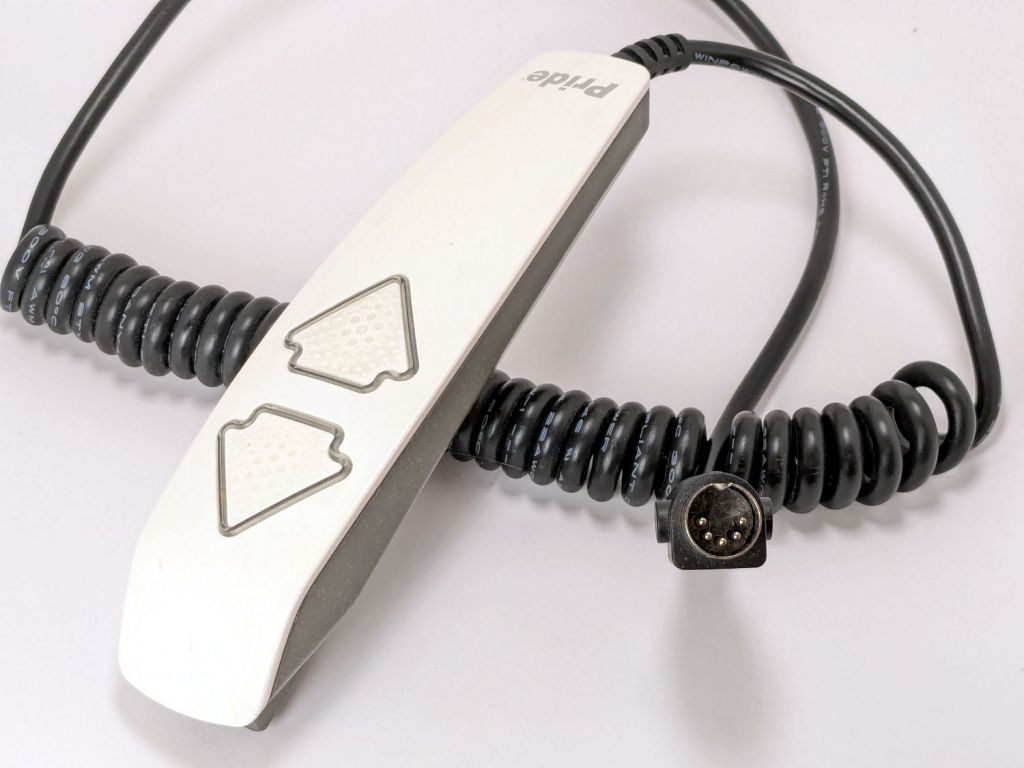
The ↓ (“down”) button on one of our lift chairs stopped working, although the ↑ (“up”) button worked fine and, as you’d expect, verifying this problem left the chair in a rather awkward position.
The usual power cycle and unplugging / replugging the control had no effect.
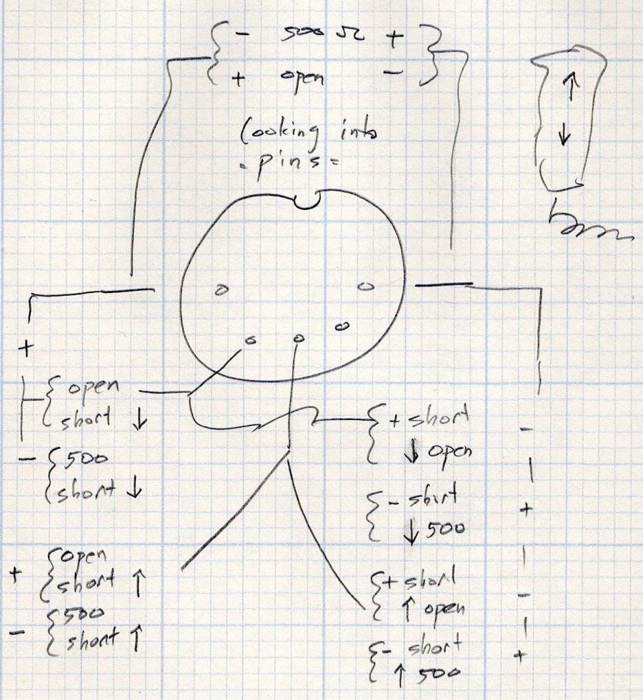
This control is the one I couldn’t pry apart to dim its LEDs, so I tried various combinations of pins until this scribble emerged:
Pride Lift Chair – control pinout doodle
I have no idea of the correct pin numbering, but the scribble looks into the connector pins with the keyway on top:
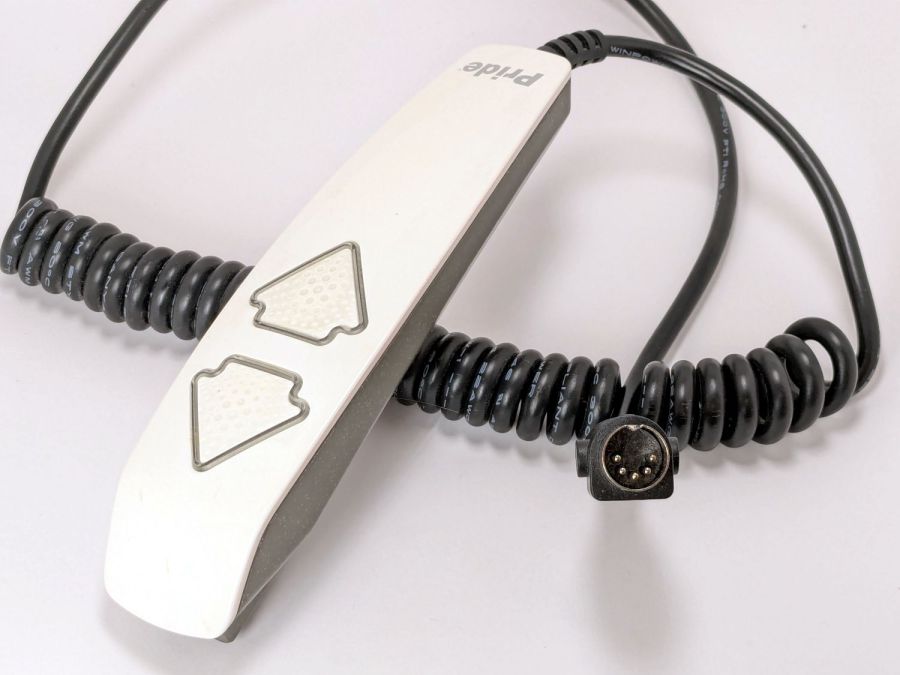
Pride lift chair control
The more intricate control for the other Pride lift chair has only four pins in its connector, so I couldn’t just swap them to see what happened.
The polarities are for the continuity / resistance test probes.
The takeaway: The two buttons did similar things to two different connector pins, so the control seemed to be working correctly and the fault lies elsewhere.
The control sports a USB jack for powering / charging your favorite device and I’m reasonably sure the control has a microcontroller tucked in there for good reason, implying the circuitry is surely more complex than maybe a rectifier bridge and some resistors.
So I shoved the chair into the middle of the room, deployed some test equipment, reconnected the control, plugged the chair power supply into the outlet strip, and … of course both buttons worked perfectly.
Soooo the chair is back in place and we’ll see what happens next.
Speaking of Heisenbugs, the HQ Sixteen continues to work fine, too.
After running reliably for a few weeks, the HQ Sixteen Heisenbug returned, displaying a Motor Stall error on the first attempt to run the motor. This gave me the opportunity to extract the PCB, compare it with the first rough schematic, then correct a few resistor values and connections.
Do not assume any connections or components are correct or correctly drawn.
!!CAUTION!! The motor supply is direct-from-the-AC-line non-isolated +160 VDC.
!!CAUTION!! The GND traces are not isolated from the AC line and are not at the normal “0 V” AC neutral potential.
When the machine operates normally, the relay pulls in with a distinct click slightly after the power switch closed. With the Heisenbug in full effect, the relay does not click, suggesting a fault in its driver circuitry.
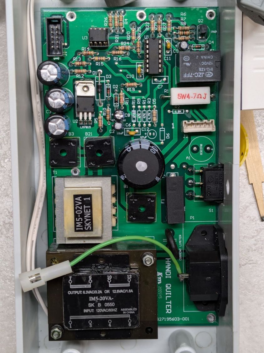
With the motor pod resting on a box beside the machine, I gingerly measured the voltage at various points on the top of the PCB. As far as I could tell, the entire +15 VDC power supply was dead: no voltage at either the input or output terminal of the LM7815 regulator!
NOTE: The obvious screws along the top edge of the PCB are not connected to the power PCB circuit GND. Instead, they’re part of the controller’s power circuitry from the isolated power supply produced by rectifier bridge B3 and passed through J1 in the upper left corner of the PCB. Instead, the left lead on R1 (the 5W sandbox resistor) is a convenient GND terminal.
So I hauled the little DSO150 battery-powered oscilloscope and a handful of clip leads up from the Basement Laboratory, got everything arranged, turned on the power, and the machine worked perfectly again.
That’s why it’s called a Heisenbug: look at it and it vanishes.
Given a faint indication of power supply problems, I verified all four diodes in Bridge Rectifier B21 are OK and the Skynet transformer windings were solid. I resoldered all the PCB connections from the transformer to U2, the LM7815 regulator, plus the green jumper wires.
The machine is now back together, it continues to work, and all my test equipment is back in the basement.
If it happens again, I’ll mount a cheerful LED on the pod to show the supply is working.
The sediment and carbon filter cartridges in our house call for annual replacement and I wondered what was inside the big cartridge.
Much to my surprise, the white plastic cap unscrews easily after grabbing the filter in the bench vise and applying a strap wrench:
Whole house carbon filter – endcap
Water enters around the perimeter of the cap, flows through the media in the cylindrical cartridge, and emerges near the center at the other end. The filter is upside-down in the vise: the cap is on the bottom of the cartridge when it’s installed in the filter housing.
The brown stuff looks a lot like sand, but is probably KDF-85 media acting as a prefilter for the carbon:
Whole house carbon filter – prefilter
The white fiber pad separates the KDF-85 from the carbon granules filling the rest of the filter:
Whole house carbon filter – carbon
Atypically, I couldn’t think of anything to do with the empty cartridge, so I screwed the lid back on and lowered the whole mess into the trash can.
The kitchen came with matched Samsung appliances dating back to 2018 and, on a frigid winter day, we piled the contents of the freezer on the porch and gave it a deep cleaning. While the empty freezer was cooling down from its adventure, I wondered:
Where were the condenser coils were located?
Did they need cleaning?
How does one do that?
The manual is strangely silent about even the existence of the coils, so evidently cleaning them wasn’t of any importance to Samsung.
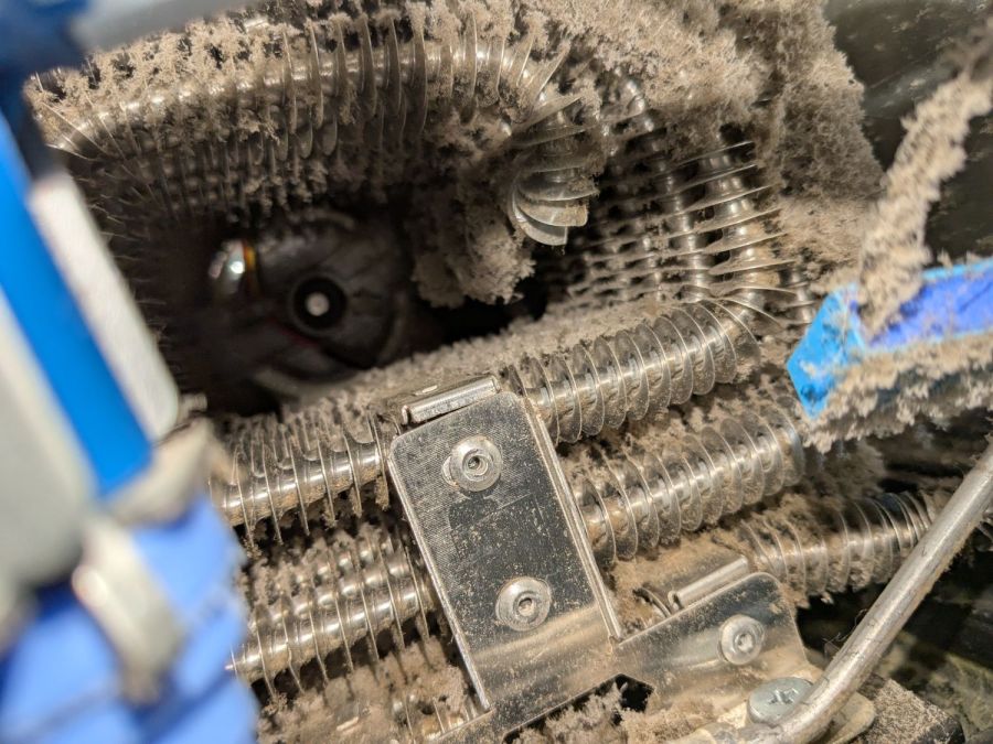
Rolling the refrigerator away from the wall just enough to get the phone camera down there suggests they exist and are in need of some attention:
Samsung refrigerator coils – first sight
Rolling the refrigerator out until the door handles met the countertop across the way let me climb over the counter and worm myself into the refrigerator-sized hole behind it, bringing along a screwdriver, the vacuum cleaner snout, and a few brushes.
Removing five screws released the back cover:
Samsung refrigerator coils – cover off
Looking into the intake end of those coils (on the right):
Samsung refrigerator coils – first intake view
So, yeah, I’m about to give them their first cleaning ever.
Five minutes of brushing fuzz, mostly into the vacuum, cleared a good bit of the exterior, but the interior needs more attention:
Samsung refrigerator coils – partial clean
Ten minutes later:
Samsung refrigerator coils – victory
Another five minutes:
Samsung refrigerator coils – intake cleaned
Making the coils cleanable and putting them where they could be cleaned were obviously not bullet-item goals for Samsung’s designers.
Although the coils are not perfectly clean, I don’t know how to get them any cleaner, despite knowing even a thin layer of fuzz kills the refrigerator’s much-touted energy efficiency. Perhaps blowing them off with compressed air, then cleaning a thin layer of dust off the entire kitchen, would help.
I think the refrigerator will be happier, at least for a while.
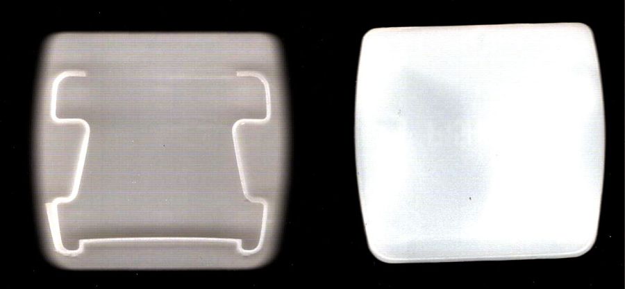
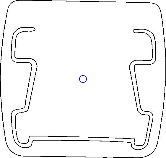
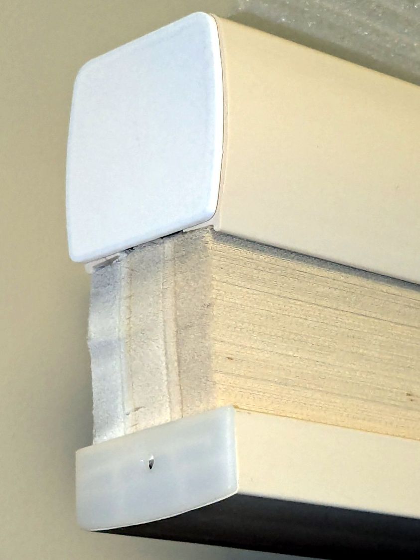
While tracking down an air leak in a living room window, I noticed one of the cellular blinds was missing an end cap, so I scanned a pair of surviving caps:
It is slightly tilted, but that doesn’t matter. You could devote more time to smoothing / reverse-engineering the shapes, but that doesn’t make much difference, either.
Inkscape exports the SVG coordinates with respect to the overall page origin in the lower left corner, so when OpenSCAD imports the SVG the paths end up far away from the origin. The trick is to put a 2 mm diameter circle at a known location, center the paths around it, then have OpenSCAD use the circle’s location to recenter the paths.
Because Inkscape uses the lower left corner of each shape as its origin, you must put the circle at (99,99) to have its center at (100,100). That is one of the many reasons you (well, I) can’t use Inkscape as a CAD program.
Import into OpenSCAD, recenter, and extrude the shapes:
CapCenter = [100,100];

PlateThick = 1.8;       // thickness of visible end cap

HolderTall = 10.0 + PlateThick;

union() {
  linear_extrude(height=PlateThick)
      translate(-CapCenter)
            import("Living Room shade end caps - Inkscape.svg",layer="Exterior");
  linear_extrude(height=HolderTall)
      translate(-CapCenter)
            import("Living Room shade end caps - Inkscape.svg",layer="Retainer");
}
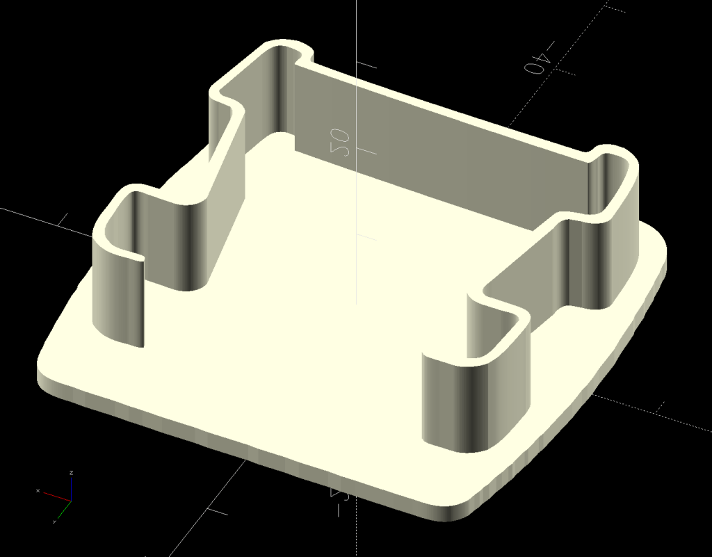
Which produces a solid model:
Living Room shade end caps – solid model
Save the model as 3mf, import into PrusaSlicer, and slice:
Living Room shade end caps – PrusaSlicer preview
Making the retainer shape a little wider would be a good idea to get better infill, but it’s a slip fit into the blind (surely why it fell out long ago) and need not withstand any stress.
Print as usual:
Living Room shade end cap – on platform
And then It Just Works™:
Living Room shade end cap – installed
It’s sitting atop a bookcase while I finish tinkering with its window.
All that seems like a lot of fiddling around, but it uses each program to its best advantage and it’s surprisingly easy after the first few models.
Because I must eventually diagnose and fix the HQ Sixteen’s Motor Stall Heisenbug, I printed out several views of the power supply PCB on glossy photo paper for best visibility.
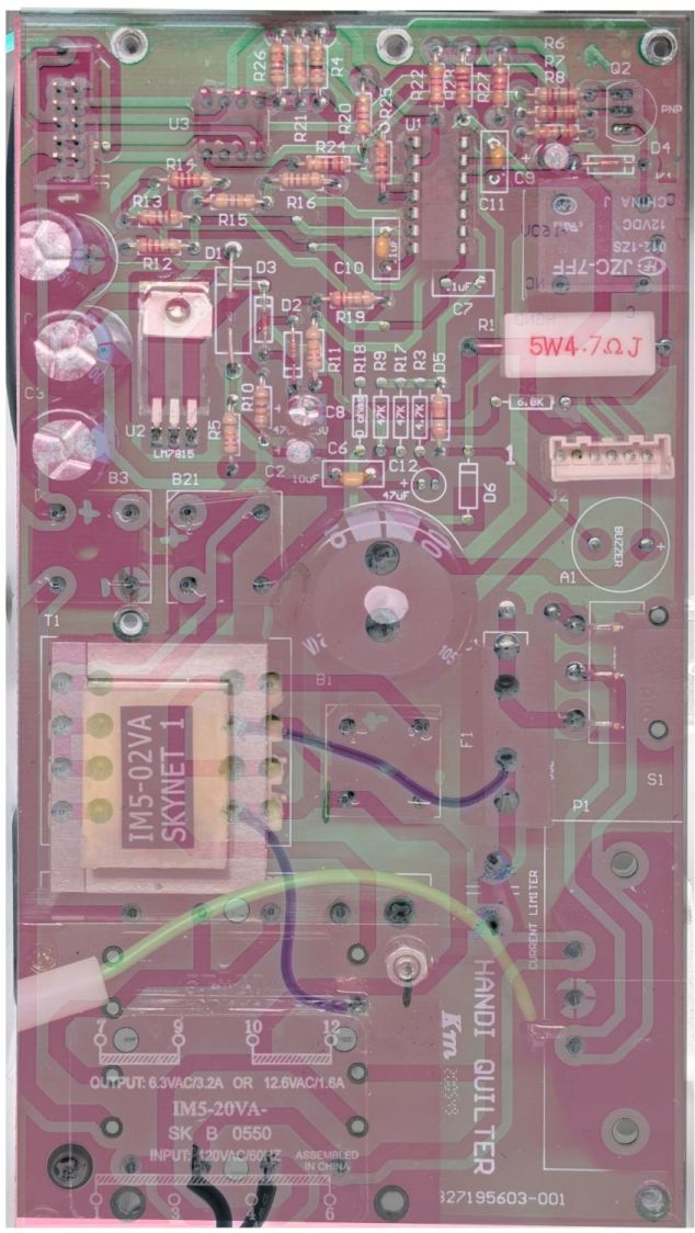
The component side:
Power PCB – components
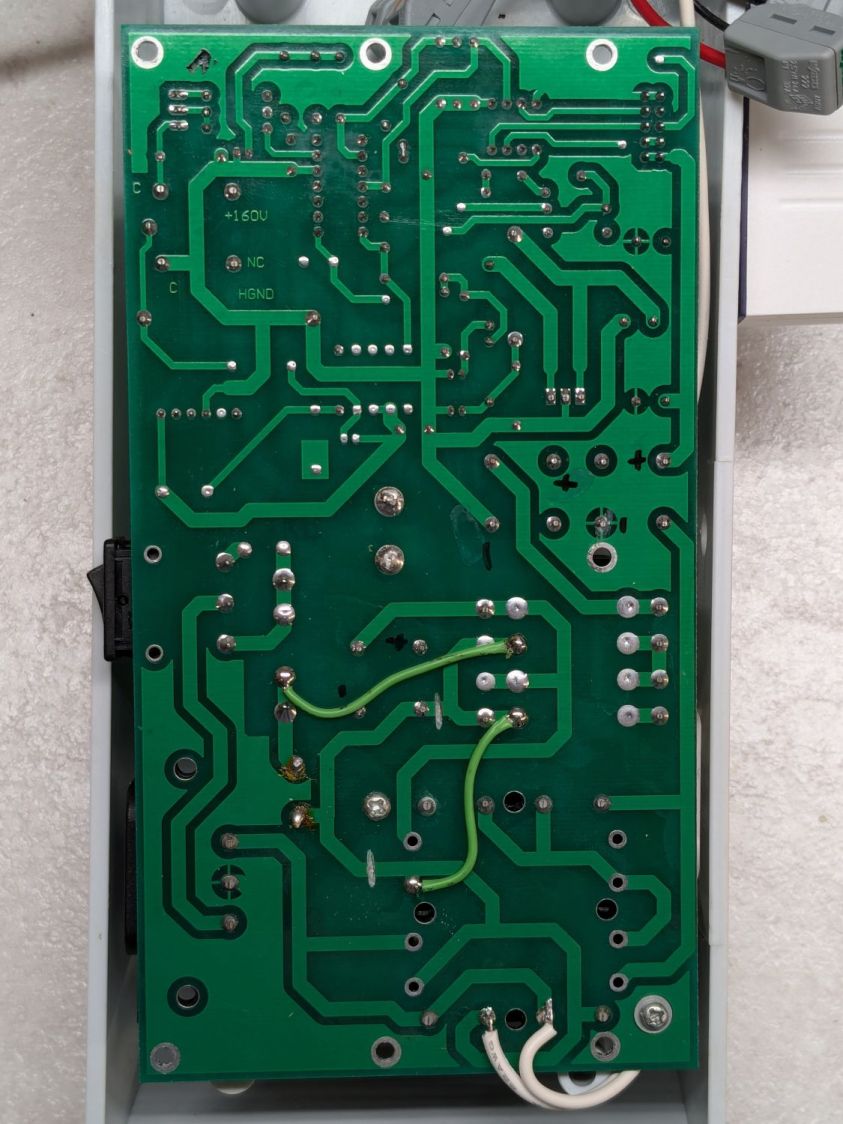
The solder side:
Power PCB – solder
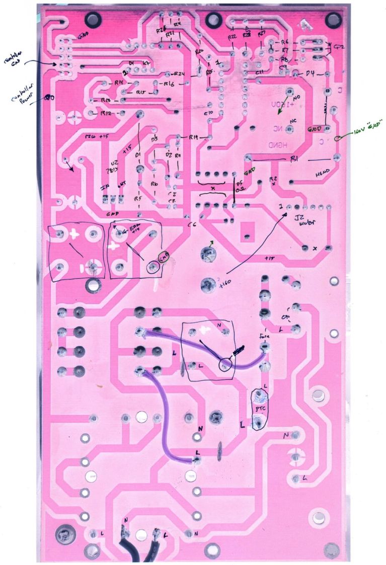
The X-ray view:
Power PCB – overlaid
Considerable pondering and sketching produced an annotated view of the solder side:
HQ Sixteen – Power PCB – solder side – component labels – reduced
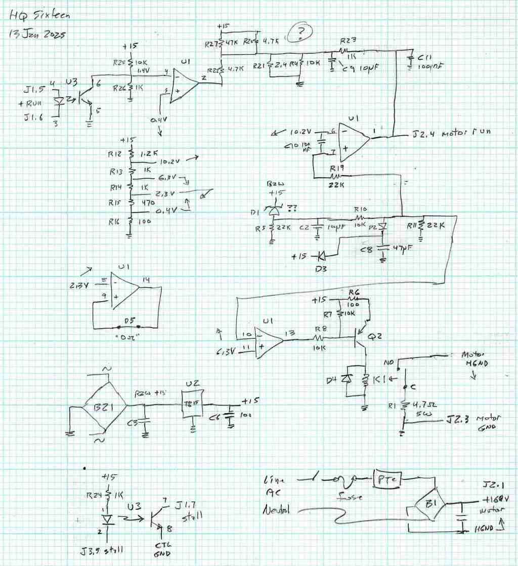
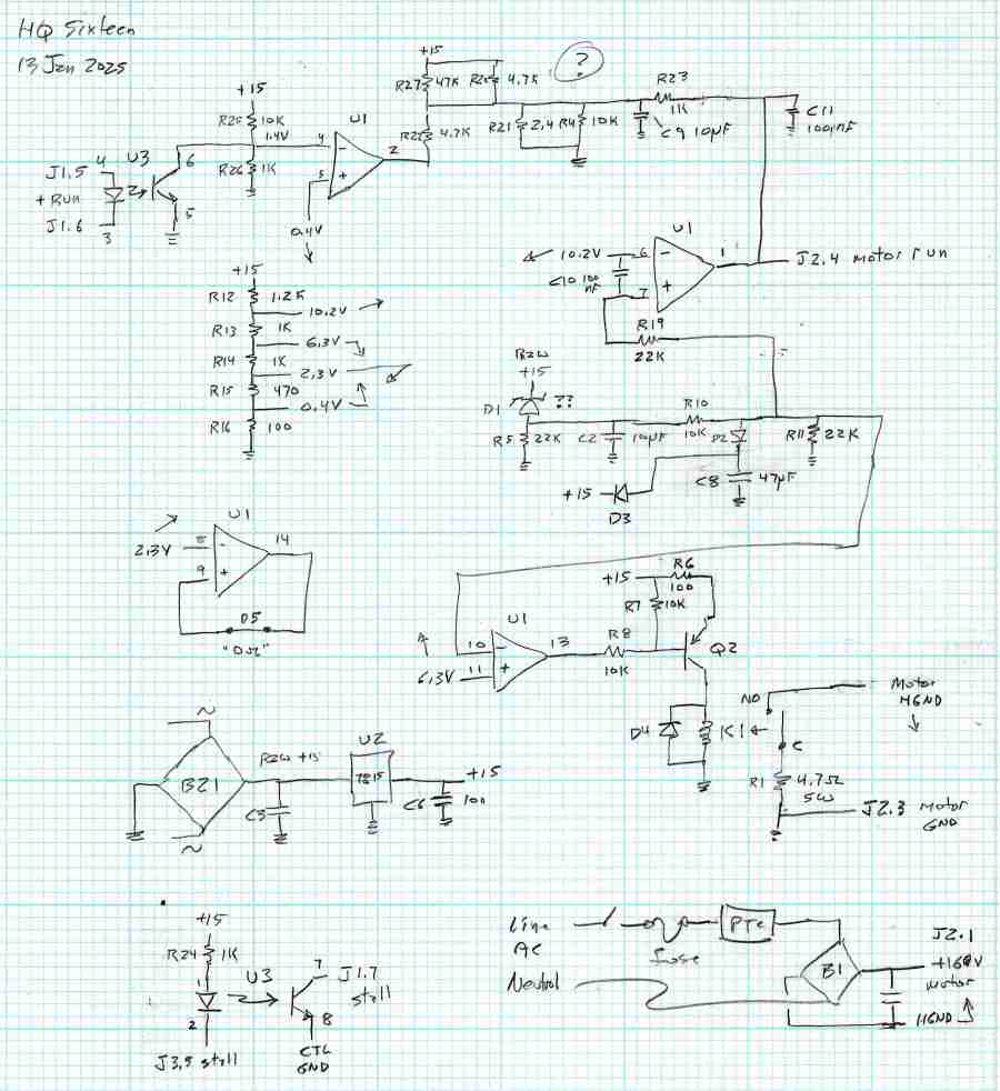
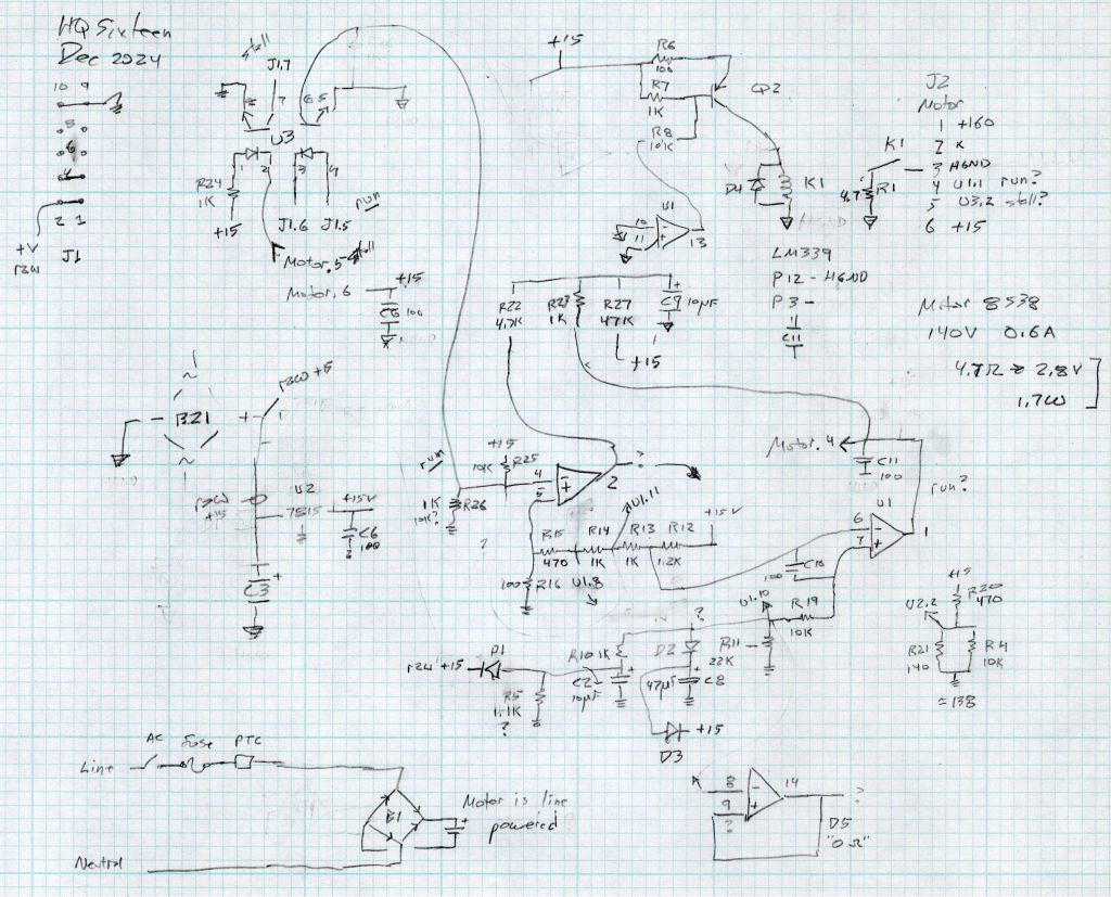
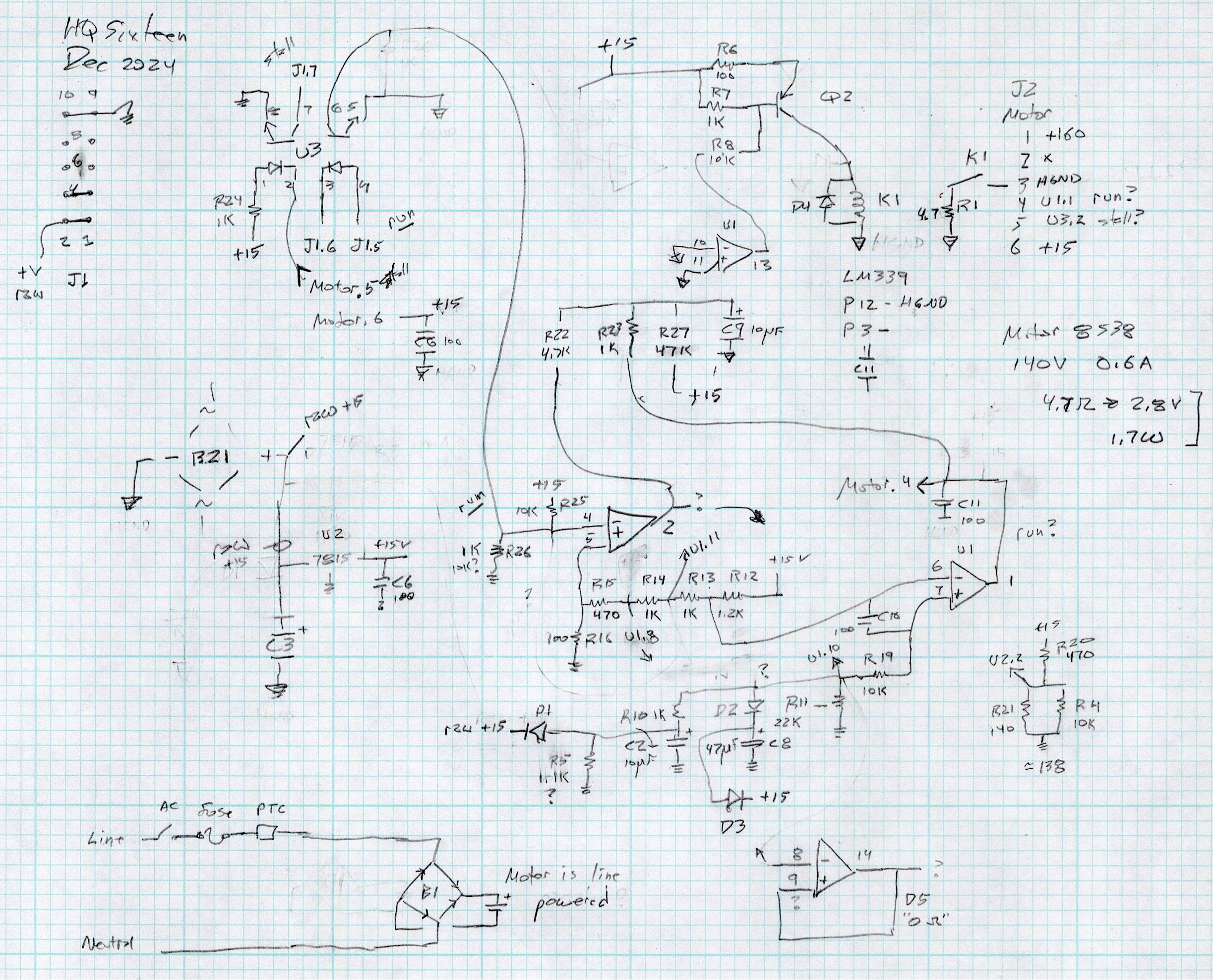
Here’s a tentative schematic drawn on the fly while extracting it from the PCB traces:
HQ Sixteen – Power PCB – rough schematic
!!CAUTION!! I have not verified the schematic against the actual hardware / PCB / components, as the Heisenbug has not reoccurred and I had no occasion to take the machine apart for checking. Do not assume any connections or components are correctly drawn.
Before I redraw the schematic in a more useful format, I must verify several nodes, because not everything in there makes sense.
In particular, the elaborate resistor string in the middle of the page seems to establish reference voltages for everything else, from the motor power supply turn-on delay to the RUN signal starting the motor.
The optoisolators definitely get the RUN command signal from the controller and feed the STALL motor status back to it. That’s assuming I understand enough to pin those labels on those connections.
!!CAUTION!!Read my caveats about the direct-from-the-AC-line non-isolated +160 VDC motor supply before connecting your instruments. The GND traces are not isolated from the AC line and are not at the normal “0 V” AC neutral potential.
But if this mess gets you further along with whatever you were doing, let me know how it all worked out for you.


