The Smell of Molten Projects in the Morning

Ed Nisley's Blog: Shop notes, electronics, firmware, machinery, 3D printing, laser cuttery, and curiosities. Contents: 100% human thinking, 0% AI slop.

Tag: Repairs

If it used to work, it can work again

  • Anker LC-40 Flashlight Switch Repair

    Anker LC-40 Flashlight Switch Repair

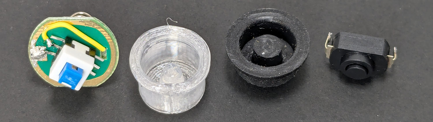
    The switch on the Anker LC-40 flashlight serving as a running light on my Tour Easy became slightly intermittent before I replaced it with a 1 W amber LED, but it was still good enough to become the troubleshooting flashlight in the tray next to the Prusa Mk 4 printer. Eventually, of course, it failed completely and Something Had To Be Done.

    Although I knew an exact replacement switch had to be available from the usual sources, I could not come up with a set of keywords capable of pulling them out of the chaff.

    That was not a problem, because the assortment of SMD switches I used to replace the handlebar control caps on Mary’s Handi-Quilter HQ Sixteen contained push-on / push-off switches that were almost the right size:

    Anker LC-40 Flashlight - switches and caps
    Anker LC-40 Flashlight – switches and caps

    Having recently convinced the MakerGear M2 3D printer to use TPU filament, all I had to do was produce a suitable cap to fit over the new switch in the flashlight’s tail:

    Anker LC-40 Flashlight Button - TPU PrusaSlicer
    Anker LC-40 Flashlight Button – TPU PrusaSlicer

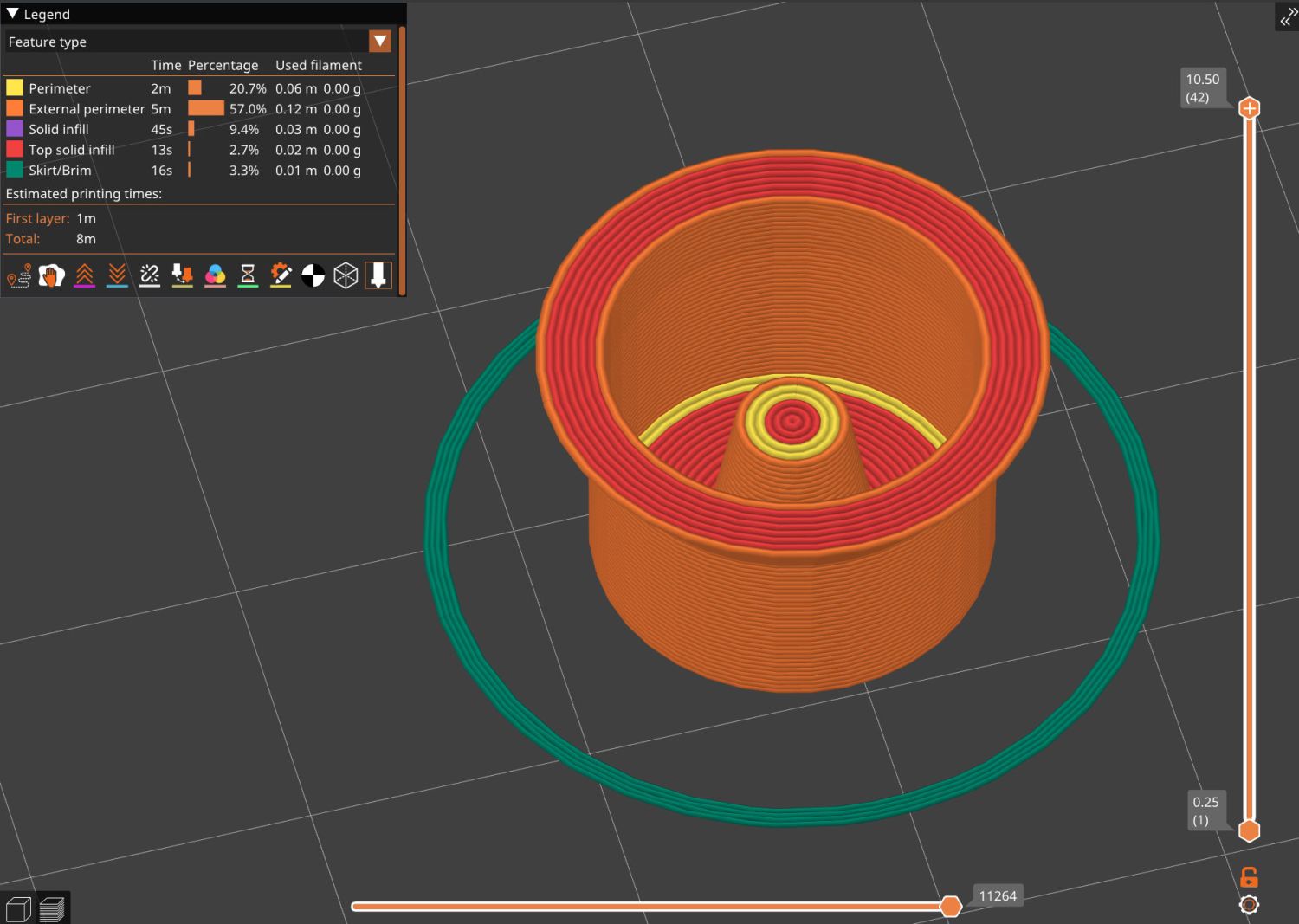
    Which turned into a multi-dimensional search over cap geometry, TPU extrusion speeds & feeds, and various impossible-to-directly-measure sizes:

    Anker LC-40 Flashlight - TPU cap iterations
    Anker LC-40 Flashlight – TPU cap iterations

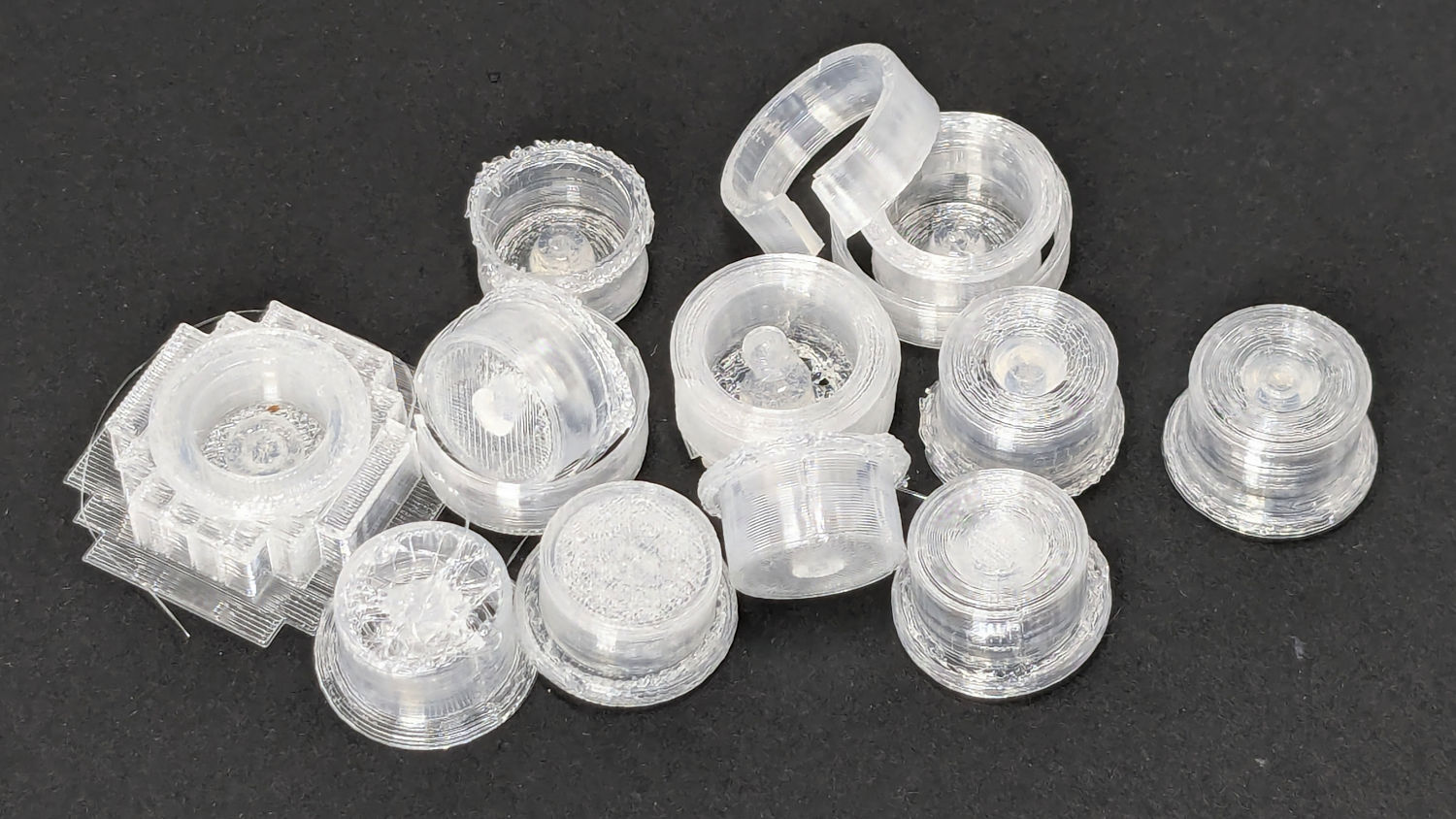
    The squarish block over on the left is PrusaSlicer’s version of a support structure wrapped around the first cap version; if human lives depended on it, I could surely extract the cap, but it would take a while.

    The remaining debris samples occured while discovering:

    • An extruder temperature of 230 °C, not 250 °C, works well
    • A conical shape of the lip around the open end to eliminate the support structure
    • TPU doesn’t bridge well, so the closed end must be down
    • Length of the central pillar to barely touch the switch stem when released
    • Cap length and wall thickness so the TPU shell can collapse enough to actuate and release the switch stem
    • And so on and so on and scooby dooby dooby

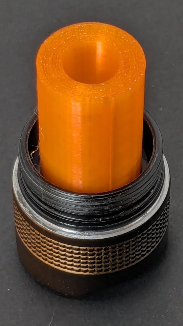
    Eventually I came up with a suitable combination:

    Anker LC-40 Flashlight - switch caps
    Anker LC-40 Flashlight – switch caps

    Because I expected this would be an easy job, I used snap ring pliers to unscrew and rescrew the threaded retaining ring holding the switch PCB in place. Because the pliers didn’t have a stable grip on the ring, the threads eventually became just a bit goobered.

    This was not a problem, because I have a(nother) 3D printer:

    Anker LC-40 Flashlight Retainer - show view
    Anker LC-40 Flashlight Retainer – show view

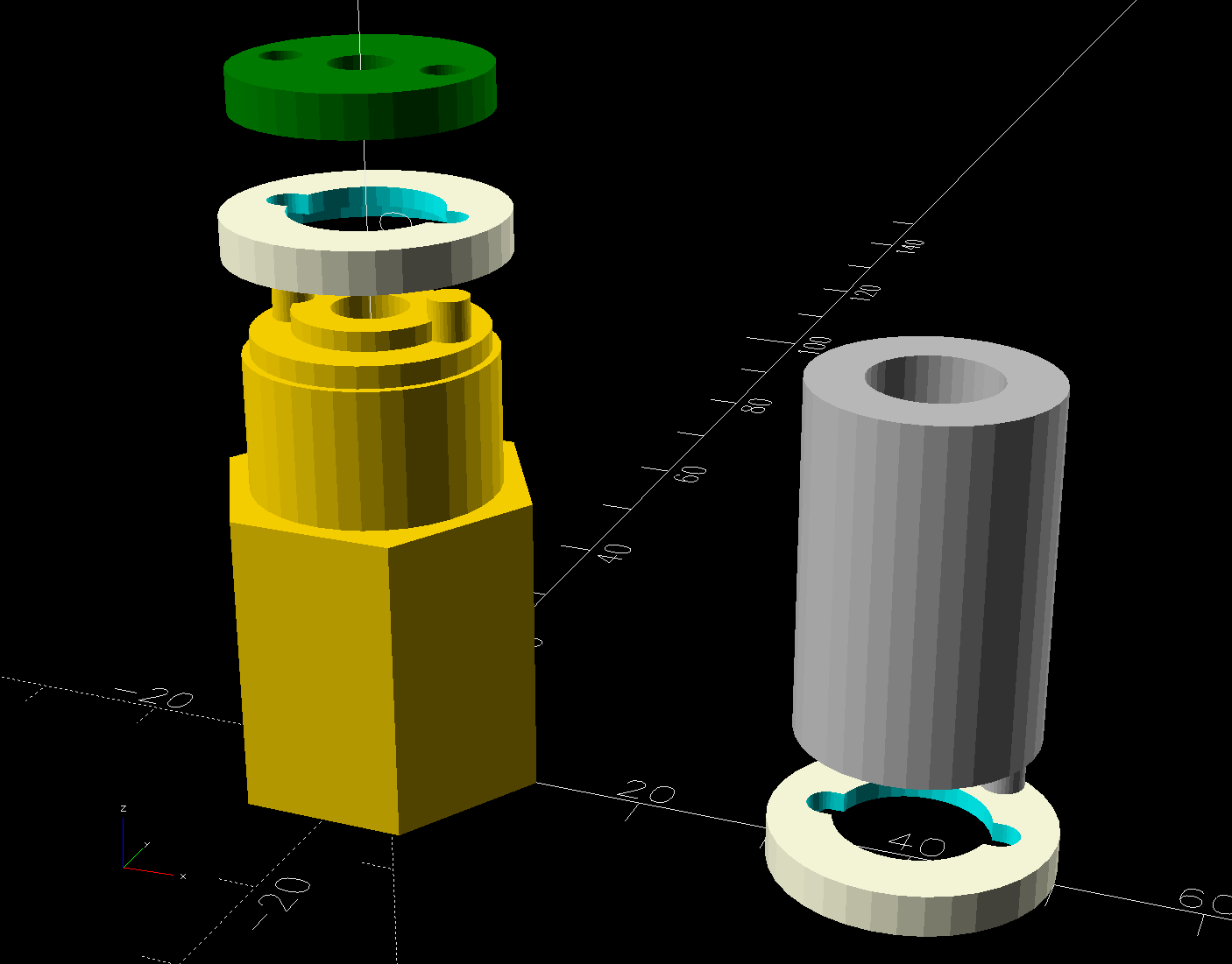
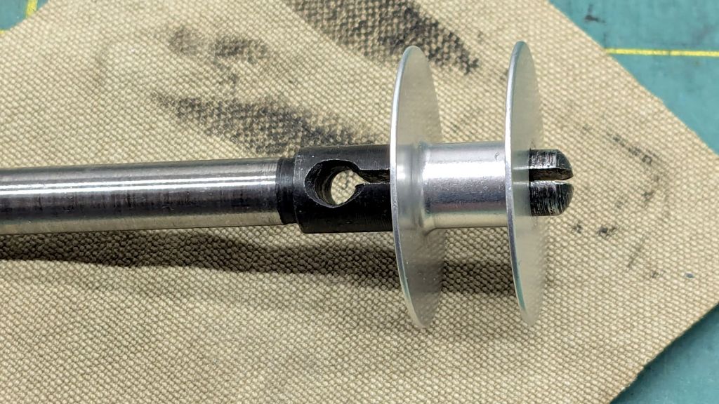
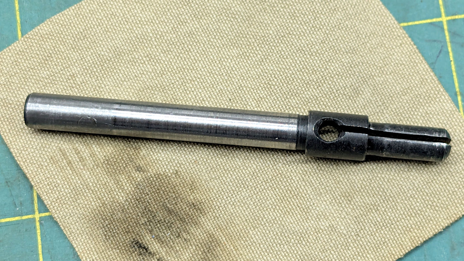
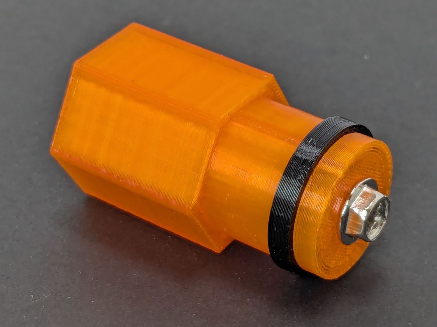
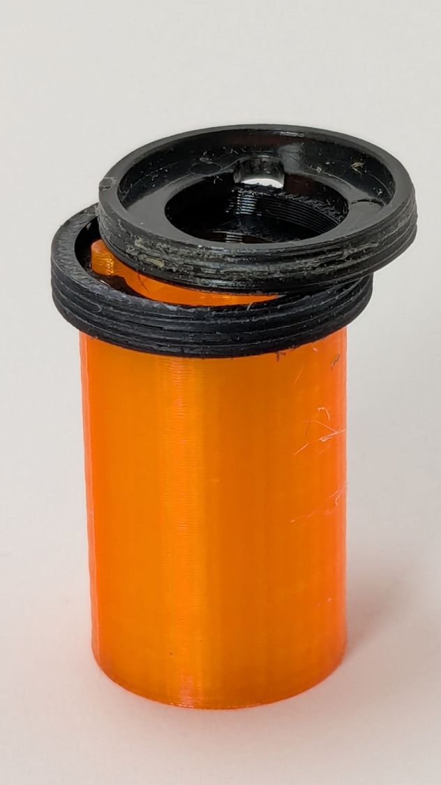
    The gray thing on the right is a simple pin wrench fitting both the original and the replacement retaining rings, so I can orient the rings properly while unscrewing & rescrewing:

    Anker LC-40 Flashlight - pin wrench in place
    Anker LC-40 Flashlight – pin wrench in place

    The threads have a 0.75 mm pitch and, while it’s possible to print screw threads, even a tedious 0.1 mm layer height would define each turn of the thread with only 7-½ layers.

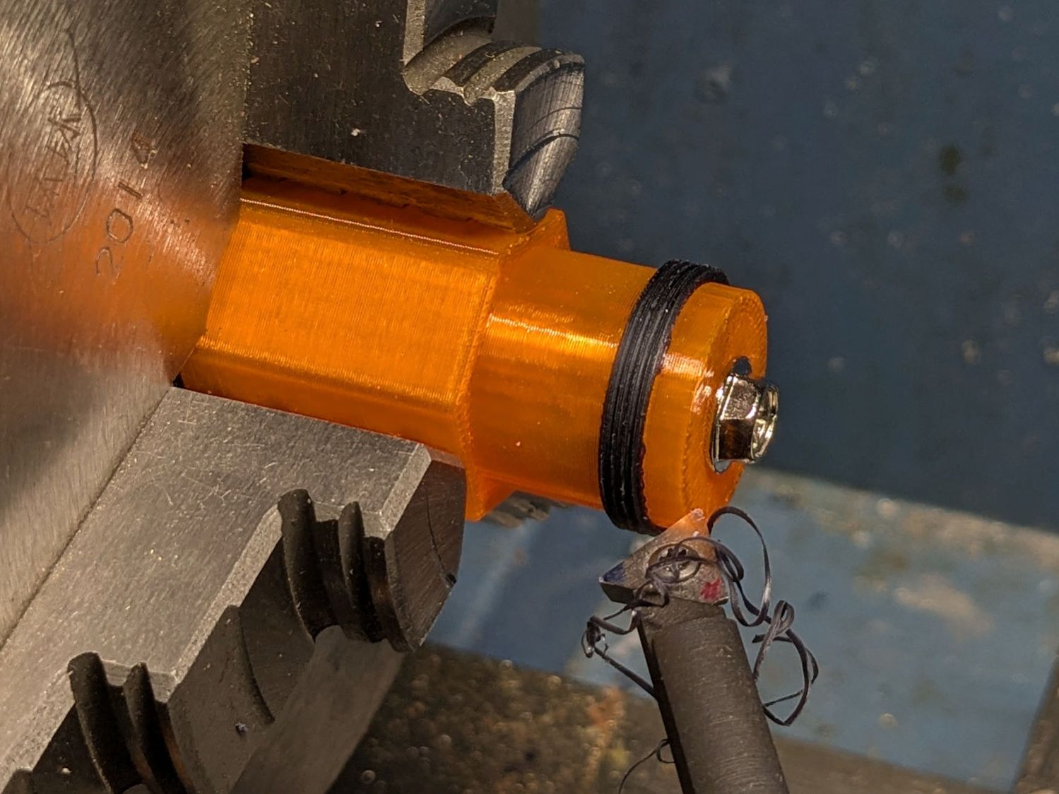
    This was not a problem, because I have a mini-lathe:

    Anker LC-40 Flashlight - thread cutting
    Anker LC-40 Flashlight – thread cutting

    The yellow & green things on the left of those solid models are the fixture holding a retaining ring for threading and the washer applying pressure to keep the ring in place:

    Anker LC-40 Flashlight - lathe fixture - detail
    Anker LC-40 Flashlight – lathe fixture – detail

    The alert reader will note that washer lacks holes for the alignment pins I added after seeing the washer sit not quite concentric on the fixture. I could call it continuous product improvement, although I doubt I’ll print another one.

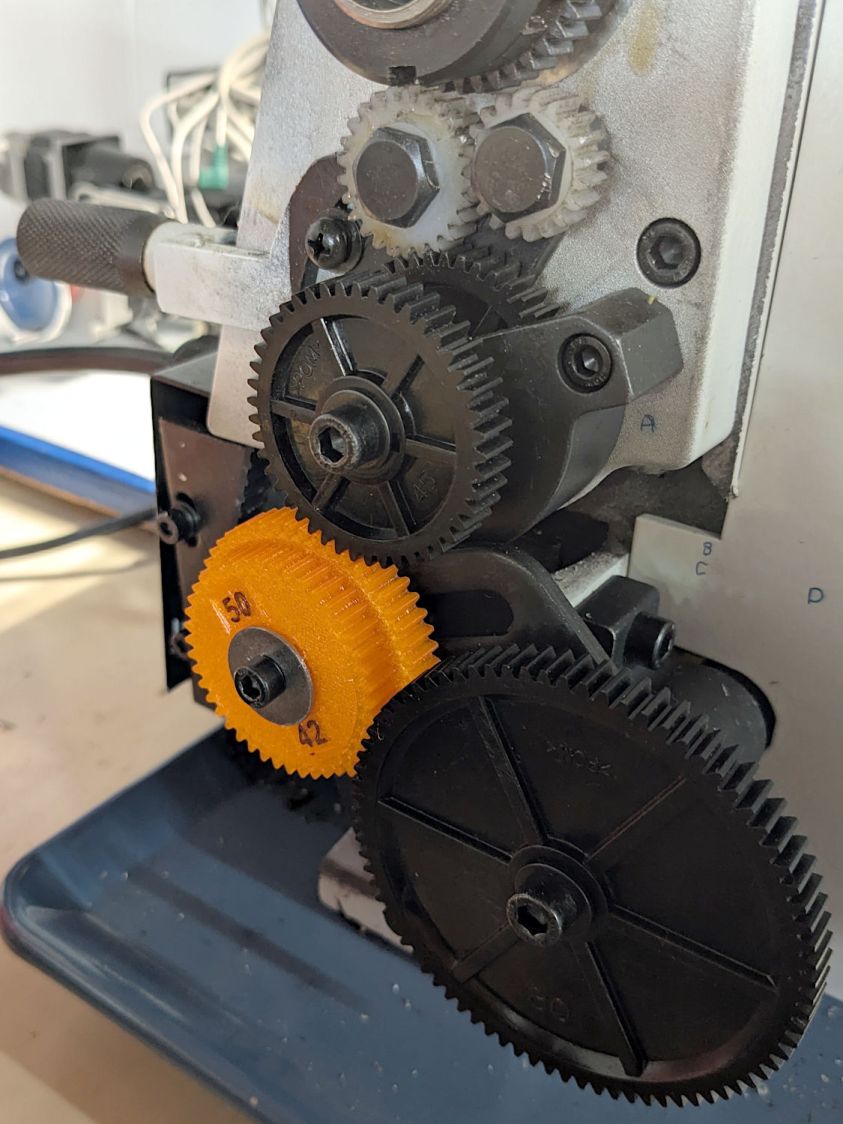
    Setting up the lathe involved finding the proper set of change gears, including the vital 42-50 stacked gear I made a while ago to print metric threads on a hard-inch lathe:

    Anker LC-40 Flashlight - lathe change gear train
    Anker LC-40 Flashlight – lathe change gear train

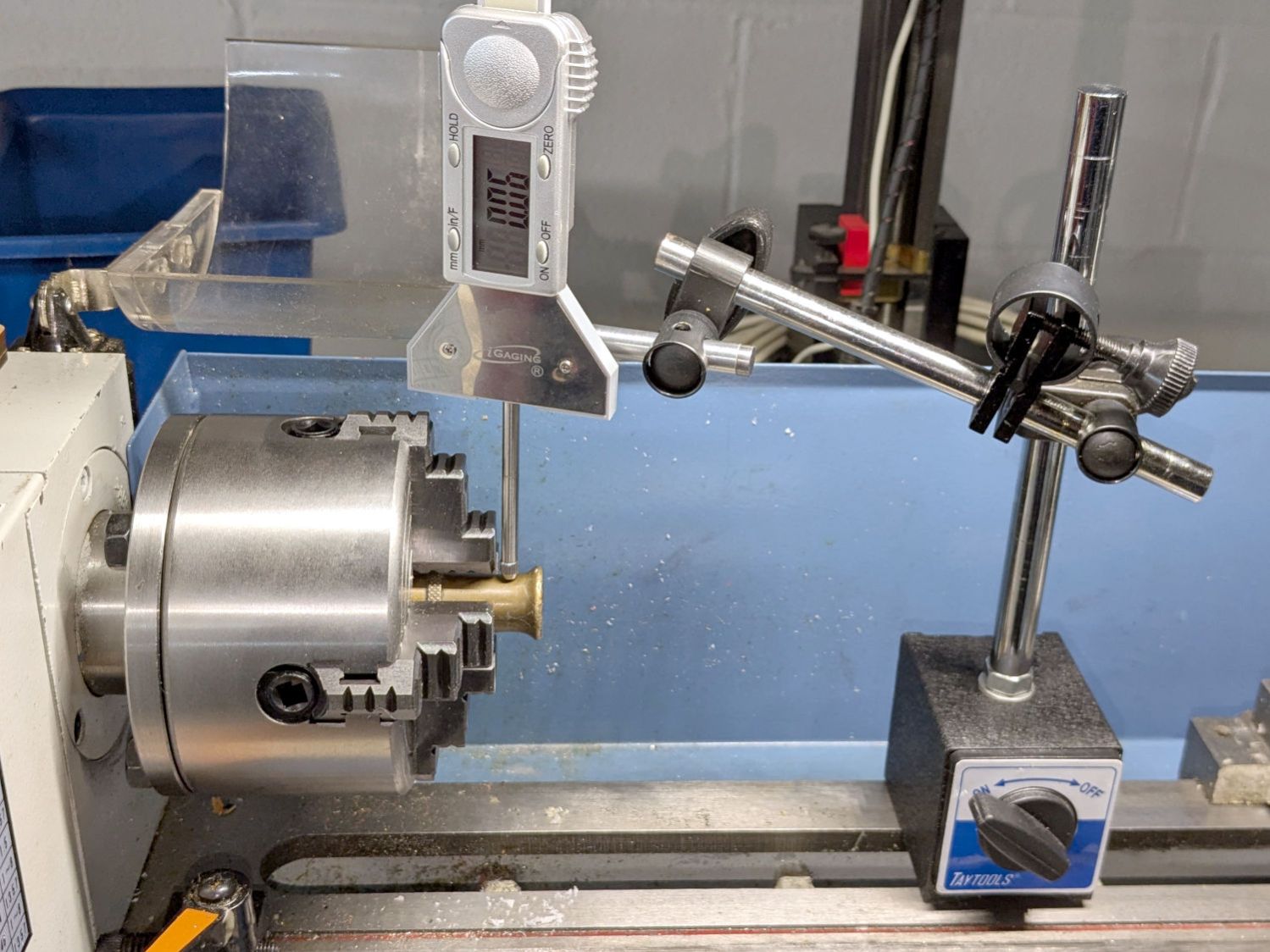
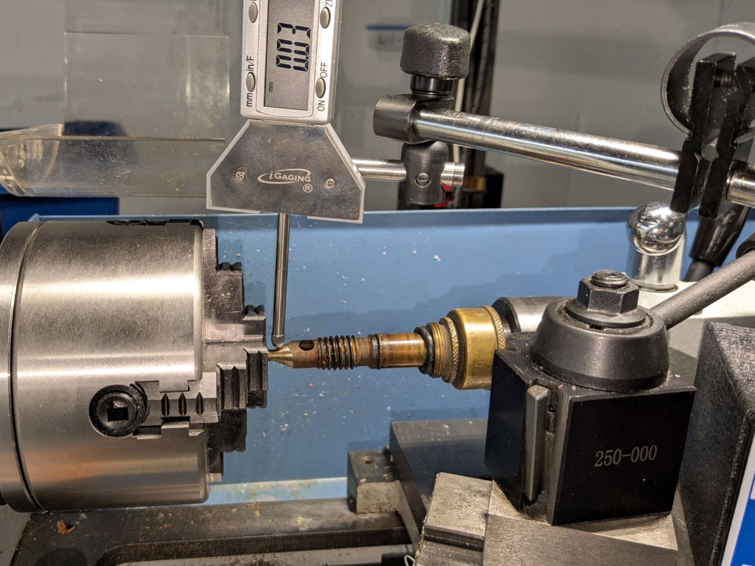
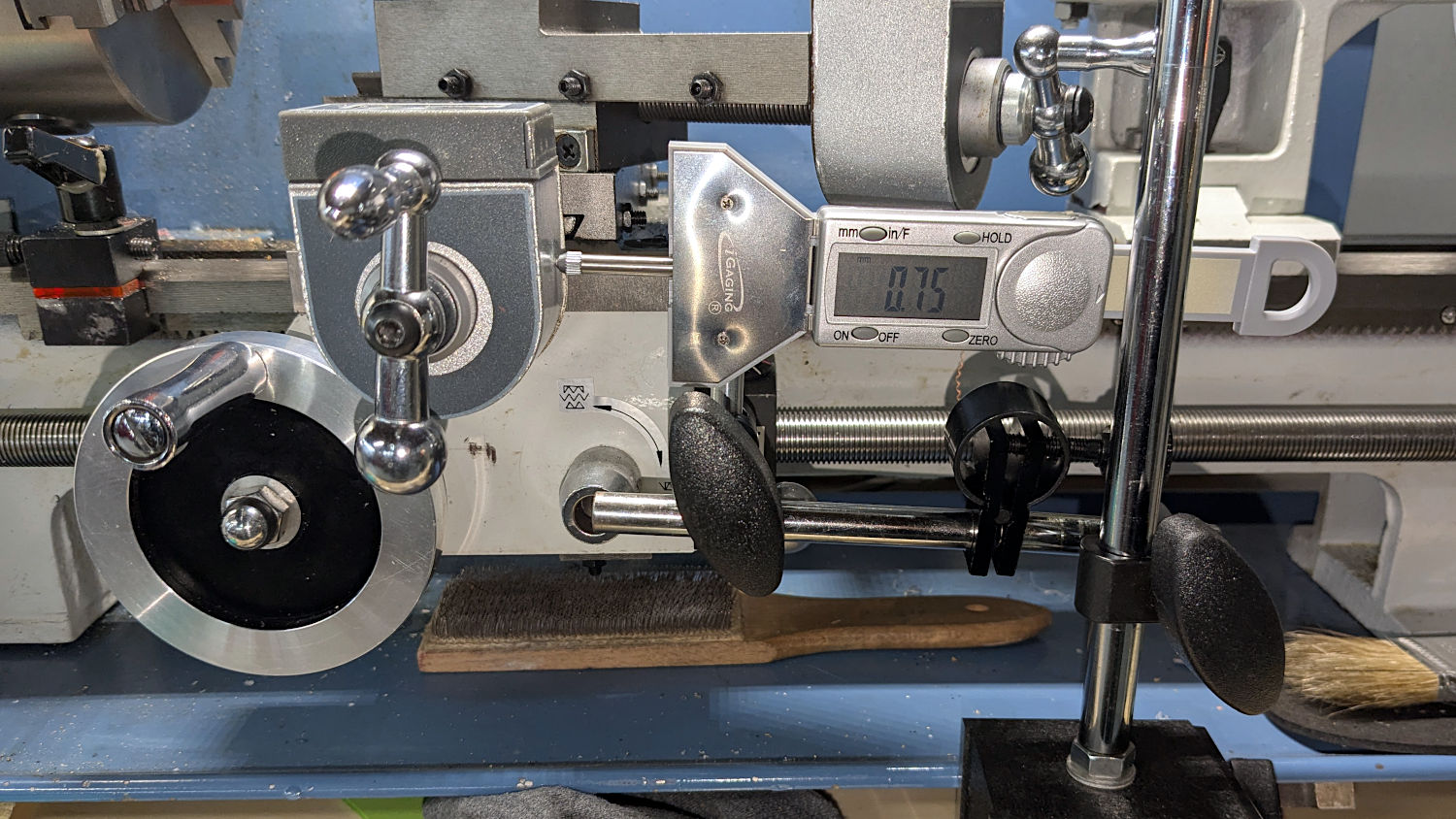
    Although you’re supposed to measure the thread spacing on a skim pass, I find it’s easier to just measure the carriage movement for one spindle rotation:

    Anker LC-40 Flashlight - lathe gear check
    Anker LC-40 Flashlight – lathe gear check

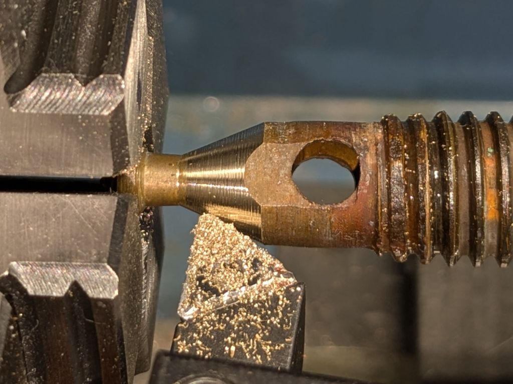
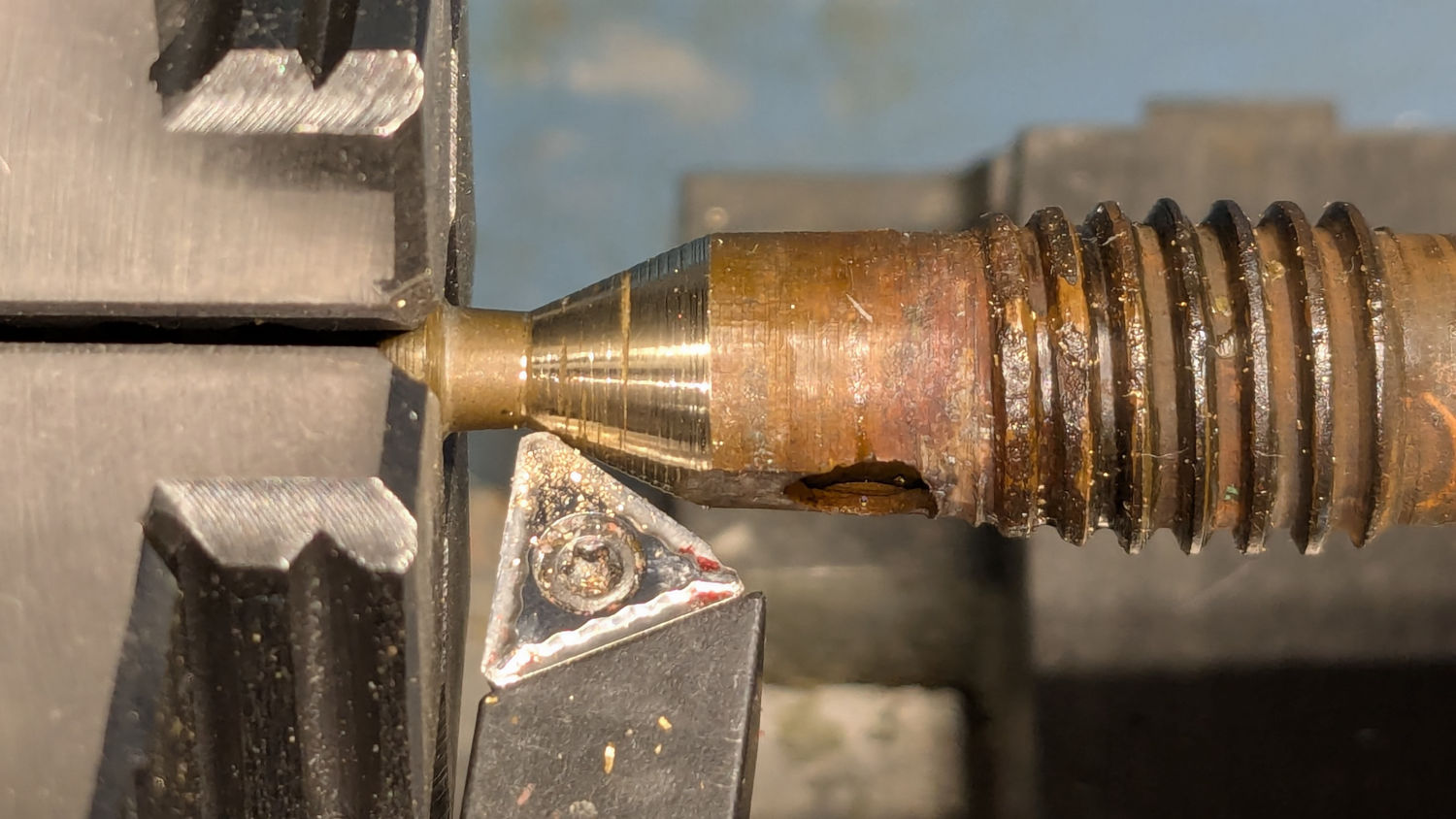
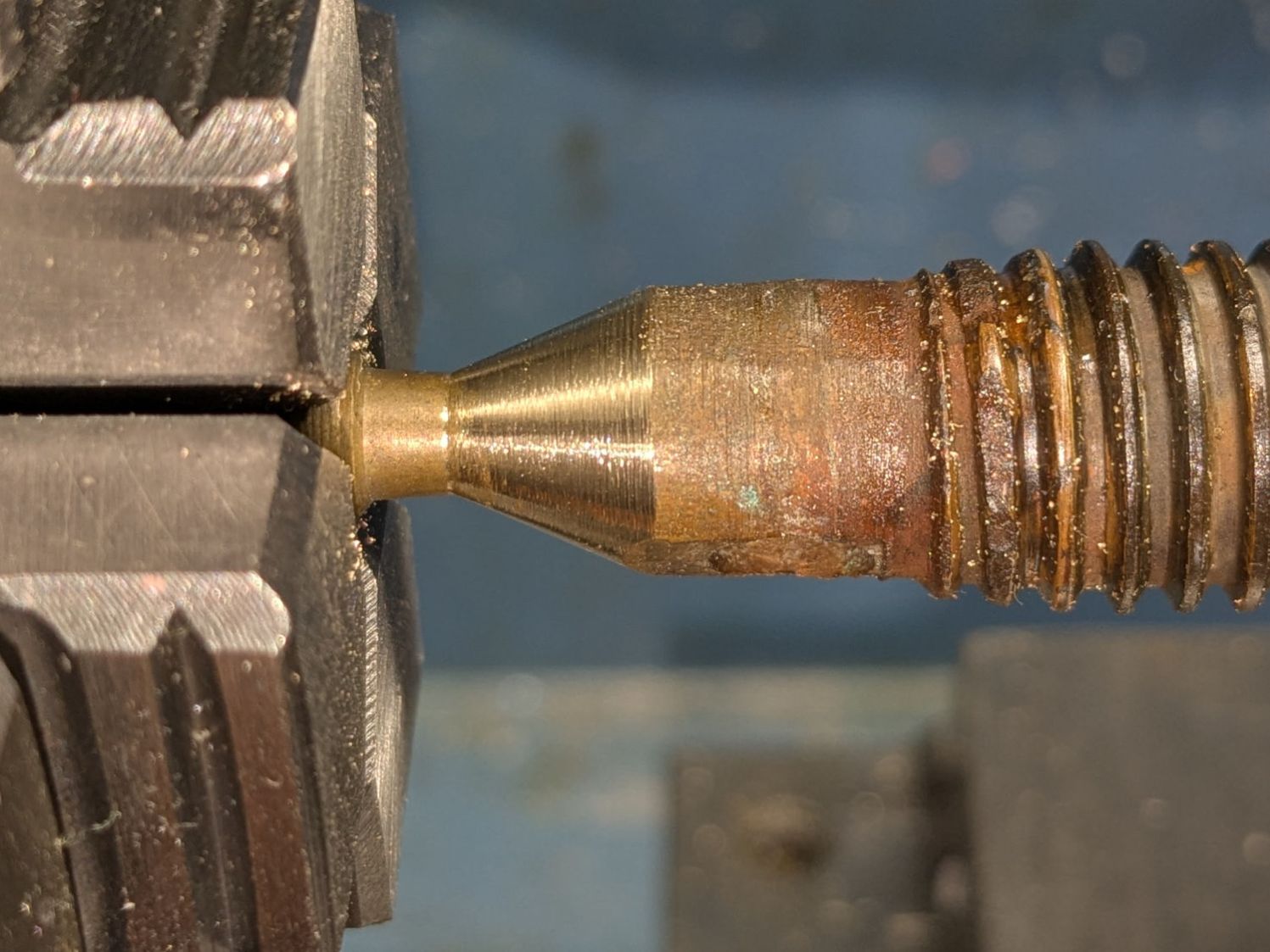
    A few passes produced a fine retaining ring:

    Anker LC-40 Flashlight - pin wrench - detail
    Anker LC-40 Flashlight – OEM vs lathe-cut threads

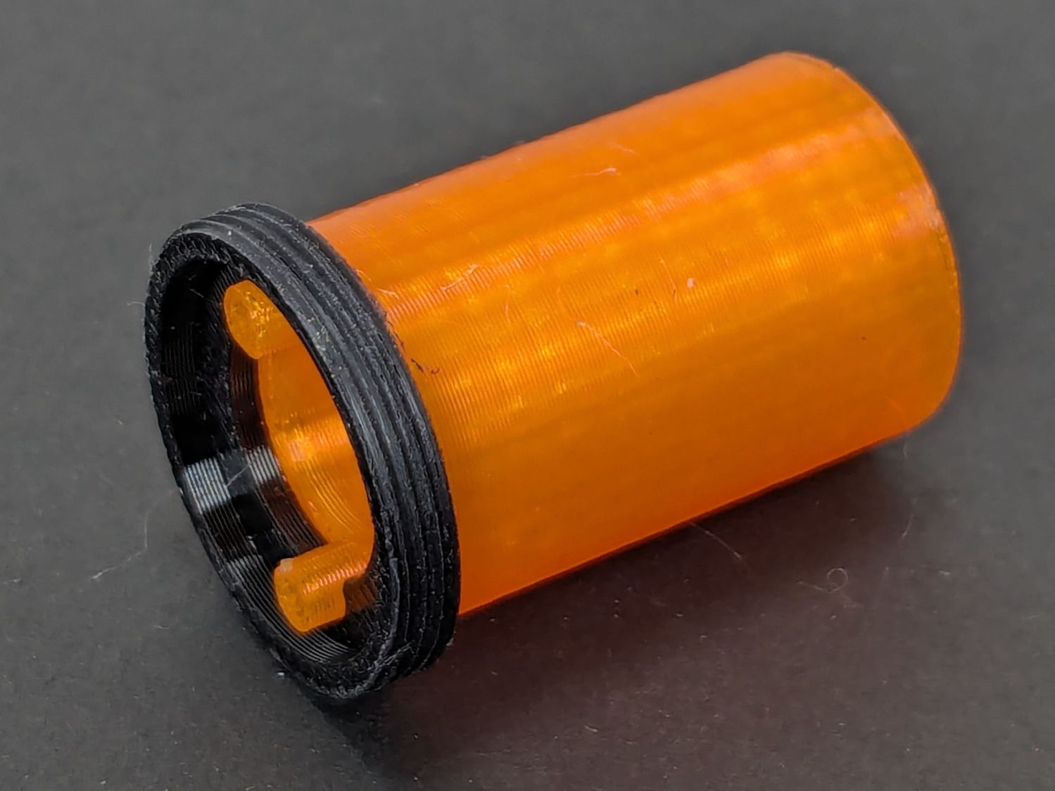
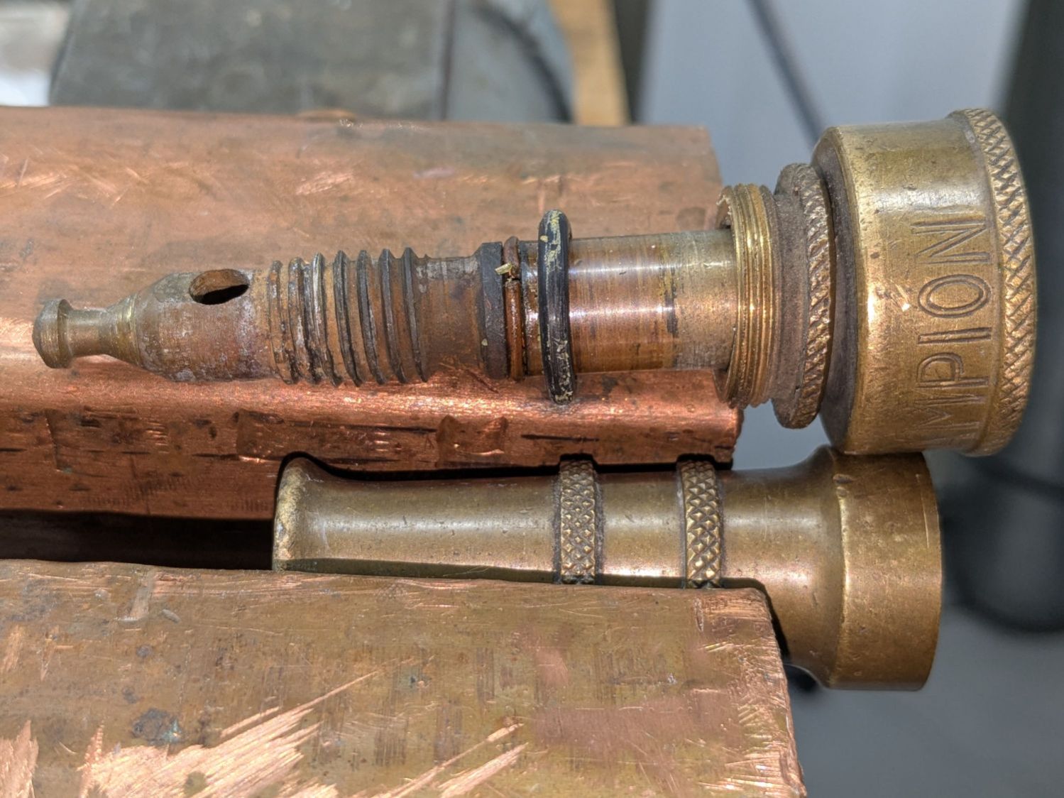
    Sporting much nicer looking threads than the goobered original:

    Anker LC-40 Flashlight - OEM vs lathe-cut threads
    Anker LC-40 Flashlight – OEM vs lathe-cut threads

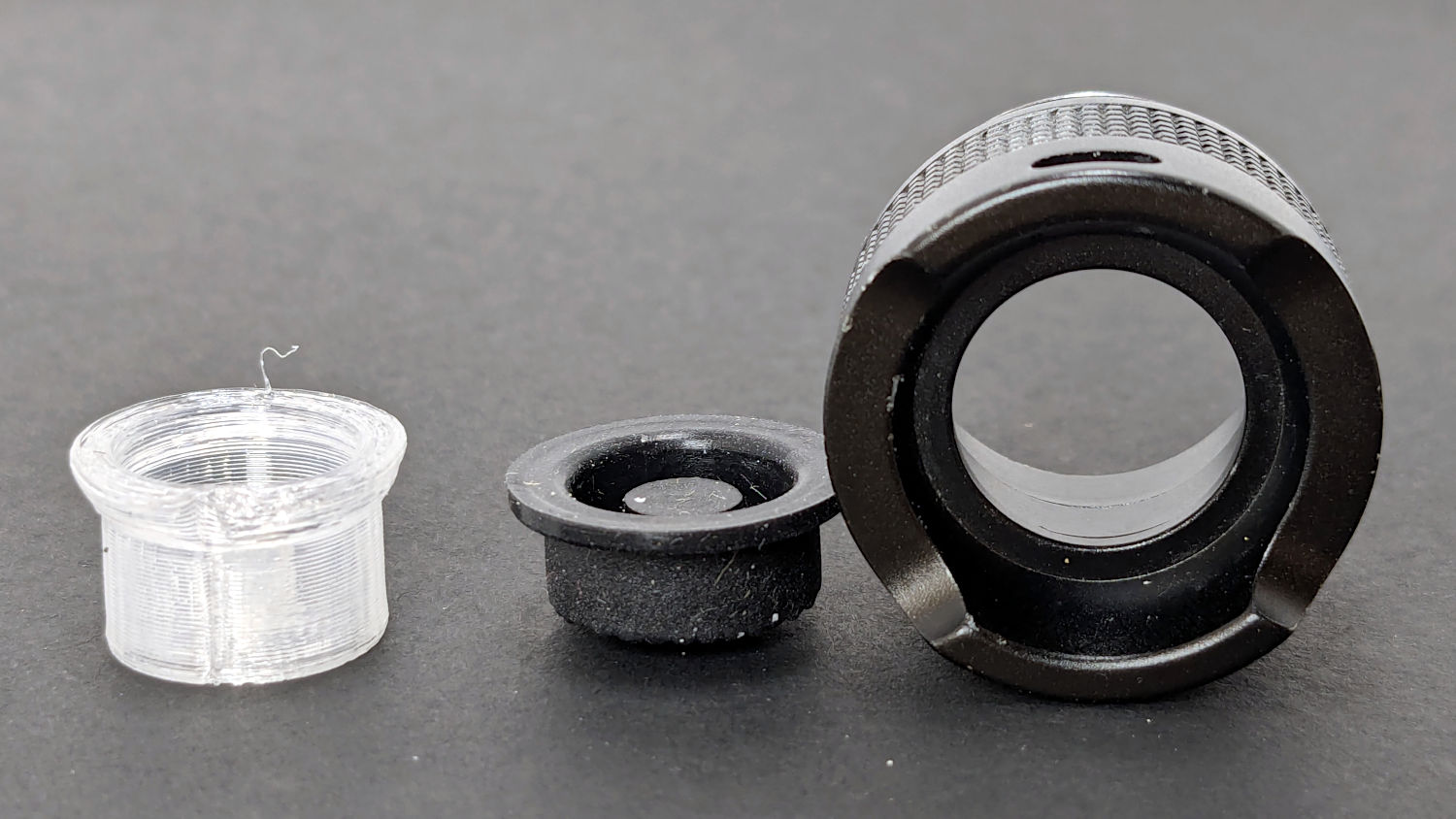
    The original switch had a stabilizing ring around the body to prevent it from wobbling under the original rubber cap.

    This was not a problem, because I have a laser cutter:

    Anker LC-40 Flashlight - new switch in stabilizer
    Anker LC-40 Flashlight – new switch in stabilizer

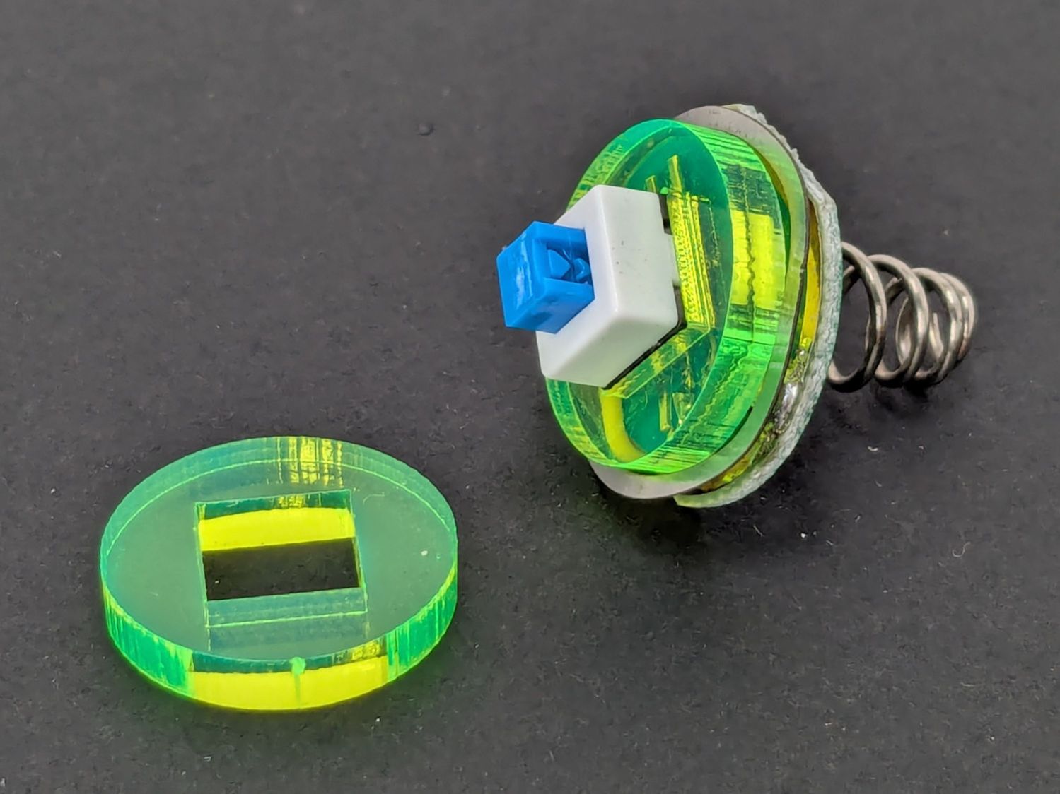
    Those came from a scrap of fluorescent acrylic.

    The wave washer behind the acrylic stabilizer improves the contact between the PCB trace around the rim and the flashlight tailcap, with the current passing through the body to the “light engine” up front. The retaining ring provides enough pressure to compress the wave washer, which is why it’s so easily goobered without a close-fitting pin wrench.

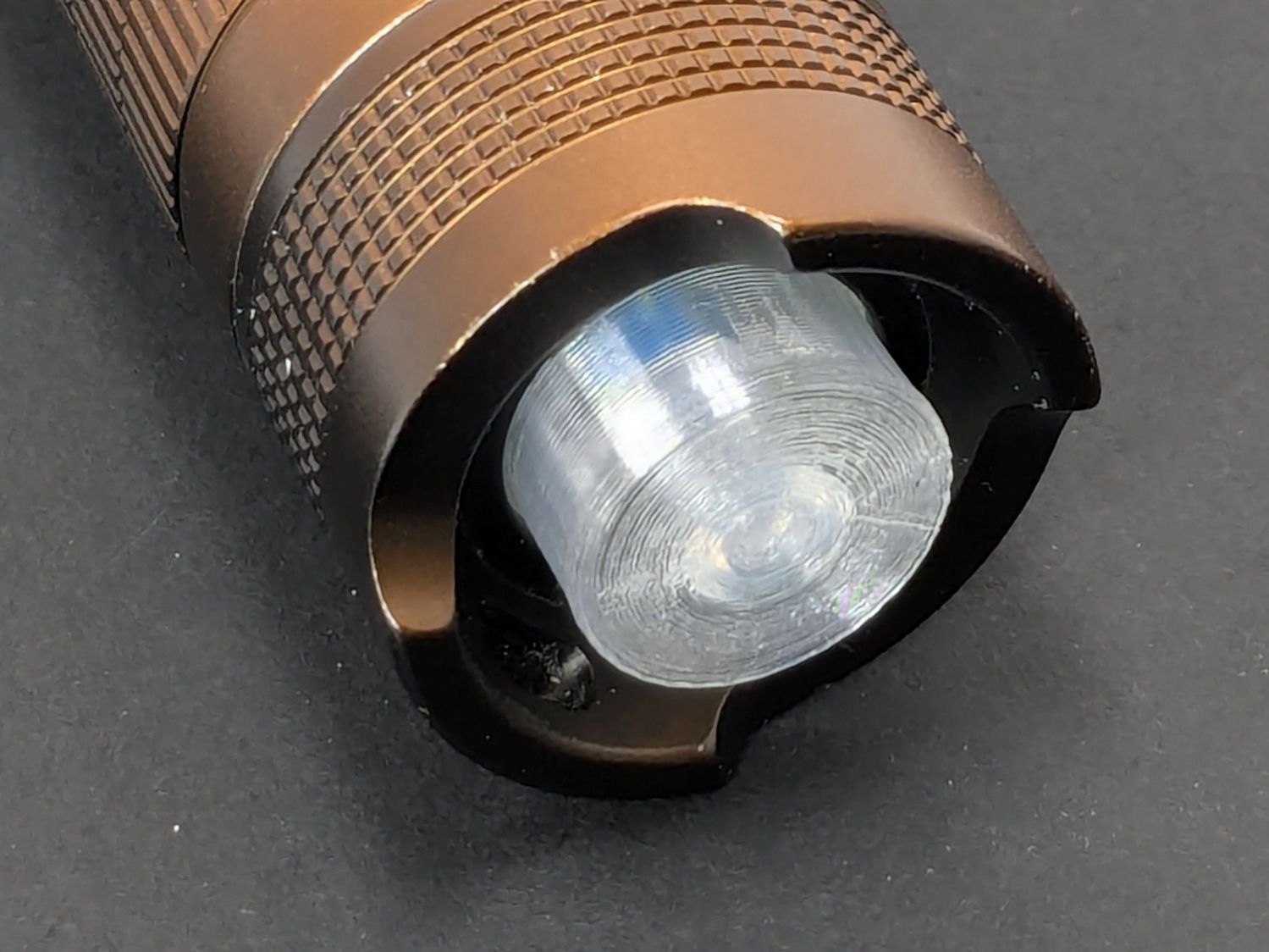
    With everything assembled in reverse order, the flashlight worked pretty much as it did back when it was new:

    Anker LC-40 Flashlight - TPU cap installed
    Anker LC-40 Flashlight – TPU cap installed

    However, after describing this during a recent SquidWrench meeting, I discovered that adding “latching” to my keywords surfaced a bodacious assortment of flashlight switches, so (a few days later) I removed the not-quite-right switch and replaced it with an identical twin of the OEM switch requiring just a little lead forming to fit the PCB.

    Even better, using the 3D printed pin wrench to screw the original retaining ring into the flashlight’s aluminum threads a few times re-formed (unrelated to recent electrolytic capacitor reforming) its goobered threads well enough to fit and work perfectly again.

    So I have:

    • … reassembled the flashlight with more-or-less original components
    • … a repair tool kit ready when another LC-40 fails
    • … re-learned the lesson that any time spent making a fixture or a special tool is not deducted from one’s allotment

    And I loves me a happy ending or two!

    The OpenSCAD source code as a GitHub Gist:

    // Anker LC-40 flashlight switch retainer
    // Ed Nisley – KE4ZNU
    // 2025-05-05
    include <BOSL2/std.scad>
    Layout = "Show"; // [Show,Build,Retainer,Fixture,Washer,Wrench]
    Gap = 5; // [0:10]
    /* [Hidden] */
    HoleWindage = 0.2;
    Protrusion = 0.1;
    NumSides = 3*3*4;
    ID = 0;
    OD = 1;
    LENGTH = 2;
    $fn=3*3*4;
    Plate = [16.8,20.0,3.0]; // retainer plate, OD allows for lathe threading
    PlateRecessDepth = 1.6;
    PlateInnerThick = Plate[LENGTH] – PlateRecessDepth;
    ClearID = 11.0;
    PinOD = 3.0;
    PinOC = 12.0;
    WrenchLength = 25.0; // handle on wrench
    JawLength = 22.0; // lathe jaw
    ThreaderOverrun = 10.0; // stick-out for threading tool clearance
    ThreadAllowance = 2*1.0; // clearance for thread depth
    //———-
    // Define Shapes
    module Retainer() {
    difference() {
    tube(Plate[LENGTH],od=Plate[OD],id=ClearID,anchor=BOTTOM);
    up(Plate[LENGTH] + Protrusion)
    cyl(PlateRecessDepth + Protrusion,d=Plate[ID],anchor=TOP);
    down(Protrusion)
    hull()
    for (i = [-1,1])
    right(i*PinOC/2) down(Protrusion)
    cyl(Plate[LENGTH] + Protrusion,d=PinOD,anchor=BOTTOM);
    }
    }
    module Fixture() {
    difference() {
    regular_prism(6,h=JawLength,d=1.2*Plate[OD],anchor=BOTTOM) position(TOP) {
    cyl(PlateRecessDepth + ThreaderOverrun,d=Plate[ID],anchor=BOTTOM);
    cyl(Plate[LENGTH] + ThreaderOverrun,d=ClearID,anchor=BOTTOM);
    // hull()
    for (i = [-1,1])
    right(i*PinOC/2)
    cyl(Plate[LENGTH] + ThreaderOverrun + Plate[LENGTH]/2,d=PinOD,anchor=BOTTOM);
    cyl(ThreaderOverrun,d=Plate[OD] – ThreadAllowance,anchor=BOTTOM);
    }
    up(JawLength + ThreaderOverrun + Plate[LENGTH] + Protrusion) // M4 burly insert
    cyl(10.0 + 5,d=5.5,anchor=TOP);
    }
    }
    module Washer() {
    difference() {
    tube(Plate[LENGTH],od=Plate[OD] – ThreadAllowance,id=4.5,anchor=BOTTOM);
    down(Protrusion)
    for (i = [-1,1])
    right(i*PinOC/2)
    cyl(2*Plate[LENGTH],d=PinOD,anchor=BOTTOM);
    }
    }
    module Wrench() {
    difference() {
    union() {
    cyl(WrenchLength,d=Plate[ID],anchor=BOTTOM);
    for (i = [-1,1])
    right(i*PinOC/2)
    cyl(WrenchLength + Plate[LENGTH],d=PinOD,anchor=BOTTOM);
    }
    down(Protrusion)
    cyl(2*WrenchLength,d=ClearID – 2.0,anchor=BOTTOM);
    }
    }
    //———-
    // Build things
    if (Layout == "Retainer")
    Retainer();
    if (Layout == "Fixture")
    Fixture();
    if (Layout == "Washer")
    Washer();
    if (Layout == "Wrench")
    Wrench();
    if (Layout == "Show") {
    color("Gold")
    Fixture();
    up(JawLength + ThreaderOverrun + Gap)
    zflip(z=Plate[LENGTH]/2)
    Retainer();
    color("Green")
    up(JawLength + ThreaderOverrun + Plate[LENGTH] + 2*Gap)
    Washer();
    right(40) {
    zflip(z=Plate[LENGTH]/2)
    Retainer();
    color("Silver")
    up(Plate[LENGTH] + Gap)
    zflip(z=WrenchLength/2)
    Wrench();
    }
    }
    if (Layout == "Build") {
    Fixture();
    right(1.5*Plate[OD]) {
    Retainer();
    fwd(1.5*Plate[OD])
    Retainer();
    }
    left(1.5*Plate[OD])
    Washer();
    fwd(1.5*Plate[OD])
    Wrench();
    }

  • S-100 Bus Computer: Capacitor Reforming

    S-100 Bus Computer: Capacitor Reforming

    I volunteered to reform the hulking electrolytic capacitors in a long-unused S-100 Bus computer:

    S-100 Bus Cap Reforming - Codex 7200 Modem case
    S-100 Bus Cap Reforming – Codex 7200 Modem case

    Yes, it’s built into a recycled modem case. No, they don’t make modems like they used to, either. Regrettably, the five status indicators on the left were not set up as Der Blinkenlichten.

    The inside view:

    S-100 Bus Cap Reforming - inside view
    S-100 Bus Cap Reforming – inside view

    The multi-winding transformer in the back feeds bridge rectifiers (out of sight behind the caps) producing bulk DC:

    S-100 Bus Cap Reforming - bulk supply caps
    S-100 Bus Cap Reforming – bulk supply caps

    The gray cap is 52 mF = 52000 µF 15 V for the +5 V regulators supplying the TTL logic on each board.

    Two of the three blue caps (each 9 mF = 9000 µF 50 V) are for the +12 V and -12 V supplies. I think the third cap is a separate supply for a different purpose, but I did not trace out the wiring.

    The on-board regulators seem to use solid electrolyte caps that should still be in fine shape you should replace on principle, per ericlscott’s experience. You’d want to bring up each board separately while probing the voltages; the box of stuff accompanying the system has an extender card that should make probing easier.

    I hoped to boot the thing after restoring the caps, but a casual inspection showed wire corrosion:

    S-100 Bus backplane - jumper wire corrosion
    S-100 Bus backplane – jumper wire corrosion

    You’d want to pull the backplane out and replace those jumpers, as well as clean the bus contacts, before applying power.

    The system has two 8 inch floppy drives in a separate case with its own power supply:

    S-100 Bus floppy drives - overview
    S-100 Bus floppy drives – overview

    There was some corrosion in there, too:

    S-100 Bus Floppy Drive - optical sensor corrosion
    S-100 Bus Floppy Drive – optical sensor corrosion

    So I confined myself to reforming the caps and must let someone with more powerful motivation restore the rest of the system before trying to connect everything and booting CP/M.

    The general idea behind “reforming” an electrolytic capacitor is to regrow the oxide layer separating the anode and cathode electrodes, which involves passing a current of about 1 mA for as long as it takes to bring the terminal voltage up to the cap’s maximum rated voltage:

    S-100 Bus Cap Reforming - 52mF 15V
    S-100 Bus Cap Reforming – 52mF 15V

    That setup consists of an absurd number of PowerPole adapters putting the meter in series with a fuseholder repurposed to hold resistors to limit the current, with leads eventually ending up on the capacitor:

    S-100 Bus Cap Reforming - 52 mF 15 V cap connection
    S-100 Bus Cap Reforming – 52 mF 15 V cap connection

    The red dot is the overpressure vent, not a polarity marker.

    Apparently the Greek mu symbol wasn’t in the font available for the labels, as all the capacitors use m in its place: that capacitor is 52 mF = 52000 µF.

    The white plastic ejection handle belongs on the right end of the CPU board seen in the second picture, which was not plugged into its slot when I opened the case. I snapped the handle in place and plugged the board in just to keep it out of trouble. The case does not have board guide slots along the edges that would let the handle eject the board, but all that was definitely in the nature of fine tuning back then.

    I started with +15 V through a 16.9 kΩ resistor and swapped in 3.3 kΩ, 1 kΩ, and 220 Ω resistors as the cap voltage crept upward over the course of two days and eventually settled to a steady state:

    S-100 Bus Cap Reforming - 52mF 15V final voltage
    S-100 Bus Cap Reforming – 52mF 15V final voltage

    After discharging, the cap measured 59.5 mF with a 0.3 Ω ESR, which definitely seemed Good Enough.

    I reformed the three 9 mF 50 V caps at the same time by applying 50 V to three resistors captured on their screw terminals, changing the resistors as the voltages rose:

    S-100 Bus Cap Reforming - 50 V caps
    S-100 Bus Cap Reforming – 50 V caps

    Those three caps eventually measured (clockwise from upper right):

    • 9.66 mF, 1.0 Ω ESR
    • 9.76 mF, 2.6 Ω ESR
    • 10.46 mF, 3.4 Ω ESR

    The ESRs suggest they’re somewhat dried out, but I’d be tempted to run them anyway, because the on-board regulators should knock down the ripple.

    All of the reformed caps had leakage currents of a few hundred microamps. They’re not new capacitors and never will be, but they may be Good Enough.

    Getting the caps out of the diskette drive power supply required easing the entire supply frame / heatsink out of the case before unscrewing the capacitor clamps:

    S-100 Bus Cap Reforming - 16 mF 50V
    S-100 Bus Cap Reforming – 16 mF 50V

    That one eventually measured 22.1 mF with 0.14 Ω ESR. Its sibling, nominally 38 mF at 15 V, came in at 48.9 mF with 0.95 Ω ESR.

    The power supply PCB carries a handful of smaller aluminum electrolytic caps that are impossible to remove without unsoldering all the TO-3 transistor leads coming through the aluminum heatsink / frame, then completely dismantling the power supply:

    S-100 Bus floppy drives - power supply PCB
    S-100 Bus floppy drives – power supply PCB

    Although I reformed the big caps, I think a better plan would be to replace the whole thing with a contemporary switching supply. AFAICT it has 24 V and 5 V outputs; because we live in the future, dual-output switchers are cheap & readily available.

    And then I closed the cases to get them ready for the next part of their adventure …

  • Sandisk 64 GB High Endurance MicroSD Card: End of Life

    Sandisk 64 GB High Endurance MicroSD Card: End of Life

    After about 7.5 years (!) the 64 GB card in my Sony HDR-AS30V helmet camera breathed its last:

    SanDisk 64 GB MicroSD card - end of life
    SanDisk 64 GB MicroSD card – end of life

    Over the course of several rides I noticed many video files ended prematurely or would not play. I gave up attempting to reformat the card in overwrite mode using the Official SD Card formatter after four hours, which says the wear leveler in the card has no spare capacity.

    In round numbers, I ride 1700 miles a year at 12 mph, so the card recorded 1000 hours of 1920×1080 video at 60 frame/s, storing one 4.3 GB file every 22.75 minutes for a grand total of 12 TB of data.

    Although that’s 188 times the capacity of the card, it rarely held more than an hour or two of data at any one time, because I copy the camera video files to a 3 TB USB hard drive after each ride. I don’t know how the exFAT file system interacts with the card’s wear leveling, but overall it’s much better than the non-high-endurance cards I’d been using way back when.

    A new Sandisk 128 GB High Endurance card cost a third of what the 64 GB card did and, after setting the partition label to AS30V, it’s off to a good start:

    Street Lamp Pole - Rombout House Ln - 2025-05-07
    Street Lamp Pole – Rombout House Ln – 2025-05-07

    That’s the street lamp pole installed on the replaced base at the corner of Rt 376 and Rombout House Lane, with the barrels gradually being pushed closer and closer to the pole by turning traffic on the newly paved lane.

    That pole is not going to see the end of this year.

    Update: The barrels vanished this morning:

    Street Lamp Pole - Rombout House Ln - 2025-05-08
    Street Lamp Pole – Rombout House Ln – 2025-05-08

    Definitely the triumph of hope over experience.

  • Power Outage

    Power Outage

    This housing development was the second in Poughkeepsie to have underground utilities and, to put it mildly, a lot has rotted out over the last 70 years.

    Over the weekend, one phase of the AC power flickered and eventually failed completely, with the other phase supplying a steady 120 VAC. Central Hudson (Gas & Electric) crews located long-lost buried boxes in places not matching their maps:

    Power Outage - flooded box
    Power Outage – flooded box

    Then they pumped / bailed enough water to repair / lengthen the wires:

    Power Outage - corroded wiring
    Power Outage – corroded wiring

    I’ve never before seen anybody work on live wires underwater.

    They installed above-ground boxes to simplify The Next Time.

    Some improvisation was required:

    Power Outage - improvised cocoa stirring
    Power Outage – improvised cocoa stirring

    Gotta say, cold Fireball Cocoa tastes different than hot Fireball Cocoa.

  • Tour Easy: Broken Seat Parts

    Tour Easy: Broken Seat Parts

    So hardened socket head cap screws survive fifteen years of hard service on my Tour Easy’s seat stay:

    Tour Easy - broken seat stay screw
    Tour Easy – broken seat stay screw

    I replaced both screws with stainless steel 1-½ 10-32 socket head screws, with a reshaped head on the drive side, and we’ll see how long these last.

    A few days later the continuing creak led to finding a broken gear clamp on the left side of the seat back:

    Tour Easy - replacement seat frame clamp
    Tour Easy – replacement seat frame clamp

    Apart from the atypical lack of grime, you couldn’t tell that’s the replacement clamp, because the broken one looked exactly the same way. The clamp strap broke where it bent around the bottom edge of the seat pan bracket, probably due to the flexing caused by the broken seat stay screw.

    Riding season is in full effect!

  • HQ Sixteen: Bobbin Winder Split Shaft Tweak

    HQ Sixteen: Bobbin Winder Split Shaft Tweak

    The HQ Sixteen has much larger bobbins than Mary’s Kenmore and Juki sewing machines. It also came with a dedicated bobbin winder:

    HQ Sixteen bobbin winder - overview
    HQ Sixteen bobbin winder – overview

    That thing has a distinct Industrial Revolution aspect compared to the BarbieCore bobbin winder I laid hands on a while ago.

    Out of the photo on the right:

    • The thread cone and guide tower
    • The thread tension disks

    Mary had been having trouble winding the bobbins, as the tension seemed entirely too low and the thread did not lay smoothly across the bobbin, so she asked me to take a look.

    The motor shaft has an O-ring for friction drive against the large wheel driving the shaft with the bobbin on the other end. The small silver lever over on the left flips an over-center lock pressing the wheel against the O-ring and tripping the microswitch in the aluminum housing, thus turning the motor on. The bobbin fills until a small finger monitoring the thread level flips the lock back over center, the wheel disengages, the switch turns the motor off, and a spring drives the wheel against the rubber rod in the upper left.

    Which worked well, but all the bobbins had a loose-to-sloppy fit on the shaft, to the extent that the shaft really couldn’t drive them against any thread tension.

    Loosening the screw holding the drive wheel on the shaft lets it slip off and the shaft slides out to the front:

    HQ Sixteen bobbin winder - split shaft
    HQ Sixteen bobbin winder – split shaft

    The sides of the split shaft should press firmly against the bobbin core, but that just wasn’t happening.

    Measuring a dozen bobbins showed most had an ID of 6.04 mm, with a few around 6.01 mm; unsurprisingly, the latter had the best, albeit still loose, fit. Conversely, the split shaft had two isolated points 6.01 mm apart across a diameter, with the remainder around 5.95 mm. Those are not large differences, but it was obvious why the bobbins didn’t wind correctly.

    I filed some graunch off the split edges, then gently pushed the Designated Prydriver into the end of the split to spread the sides juuuust a little bit, until all the bobbins pushed on firmly and fit snugly:

    HQ Sixteen bobbin winder - split shaft test fit
    HQ Sixteen bobbin winder – split shaft test fit

    It reassembled in reverse order and we’ll see how it behaves during the next marathon bobbin-filling session.

  • Champion Hose Nozzle: Refreshed Seal Attempt

    Champion Hose Nozzle: Refreshed Seal Attempt

    The battered Champion hose nozzle came into play last fall, leaked profusely when turned off, went to a Safe Place for the winter, and recently emerged:

    Champion hose nozzle - disassembled
    Champion hose nozzle – disassembled

    The conical surface (to the right of the tip) must make perfect contact with the edge of a perfect cylindrical hole in the outer shell to shut off the water, which was obviously no longer happening.

    There is no reason why that hole should still be concentric with the outside of the shell, but centering the latter in the four-jaw chuck put the hole within about 0.2 mm of where it should be:

    Champion hose nozzle - lathe centering
    Champion hose nozzle – lathe centering

    I defined that to be Close Enough™ and made the hole smooth & concentric with a teeny boring bar and sissy cuts. A drill would likely have worked well enough, too.

    Gently filing the nastiness off the cone showed it wouldn’t suffice, so center it while noting the irregular diameter all around:

    Champion hose nozzle - lathe centering cone
    Champion hose nozzle – lathe centering cone

    A skim cut revealed the need for more attention:

    Champion hose nozzle - scarred cone
    Champion hose nozzle – scarred cone

    Another tenth of a millimeter improved its disposition:

    Champion hose nozzle - improved cone
    Champion hose nozzle – improved cone

    Gentle touchup with a fine file reserved for special occasions may have been a further improvement:

    Champion hose nozzle - finish filed
    Champion hose nozzle – finish filed

    Add a dollop of silicone grease to encourage the shell to turn much more easily on the O-ring, reassemble in reverse order, and top it off with a new hose washer.

    A quick test on a reasonably warm day showed the cone met the cylinder poorly enough to consign this nozzle to the brass recycling box.

    It was fun trying, though …