Ed Nisley's Blog: Shop notes, electronics, firmware, machinery, 3D printing, laser cuttery, and curiosities. Contents: 100% human thinking, 0% AI slop.
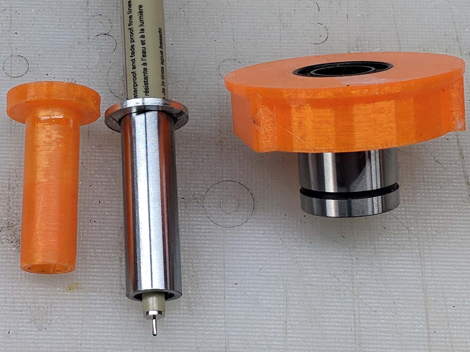
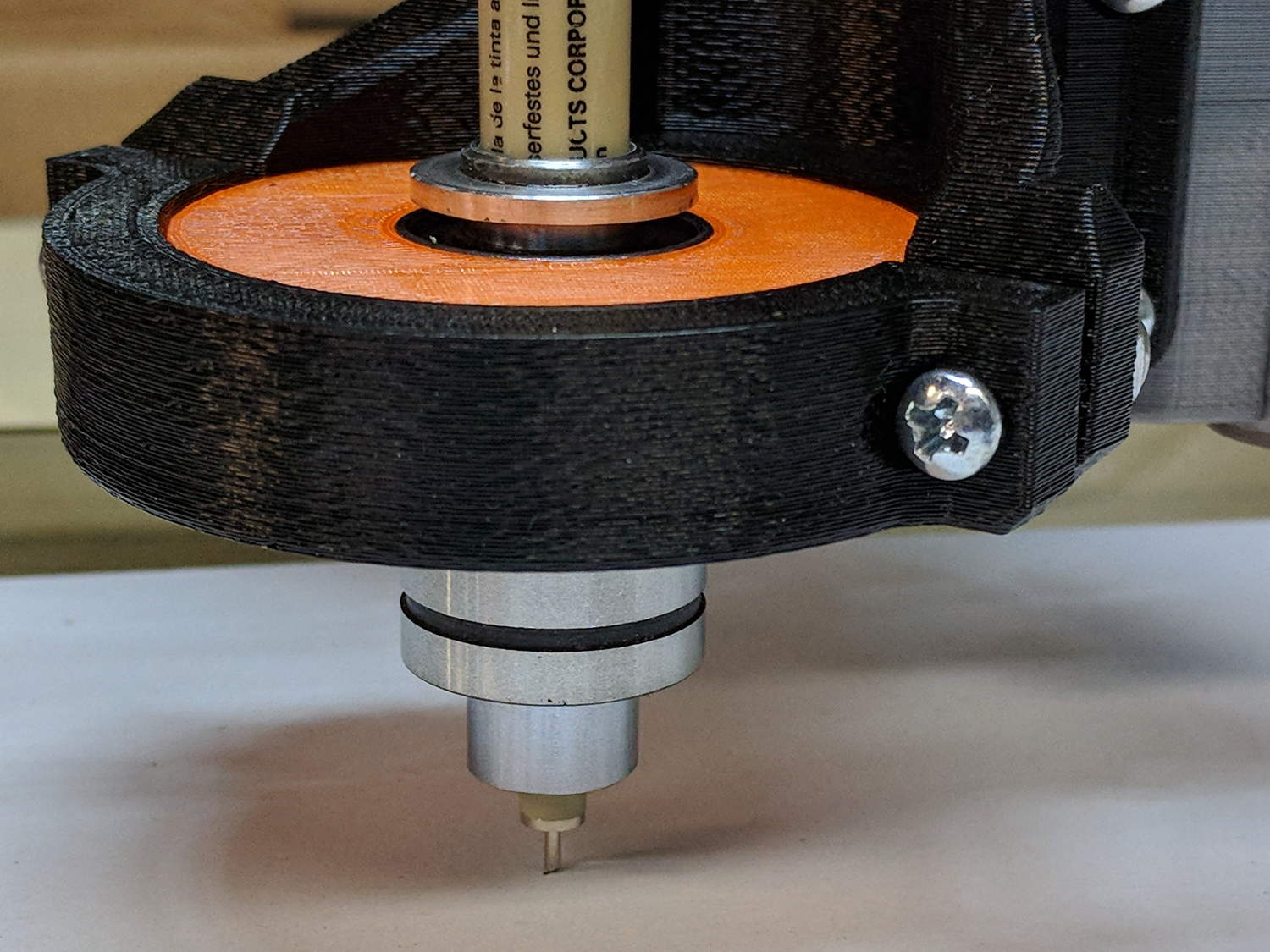
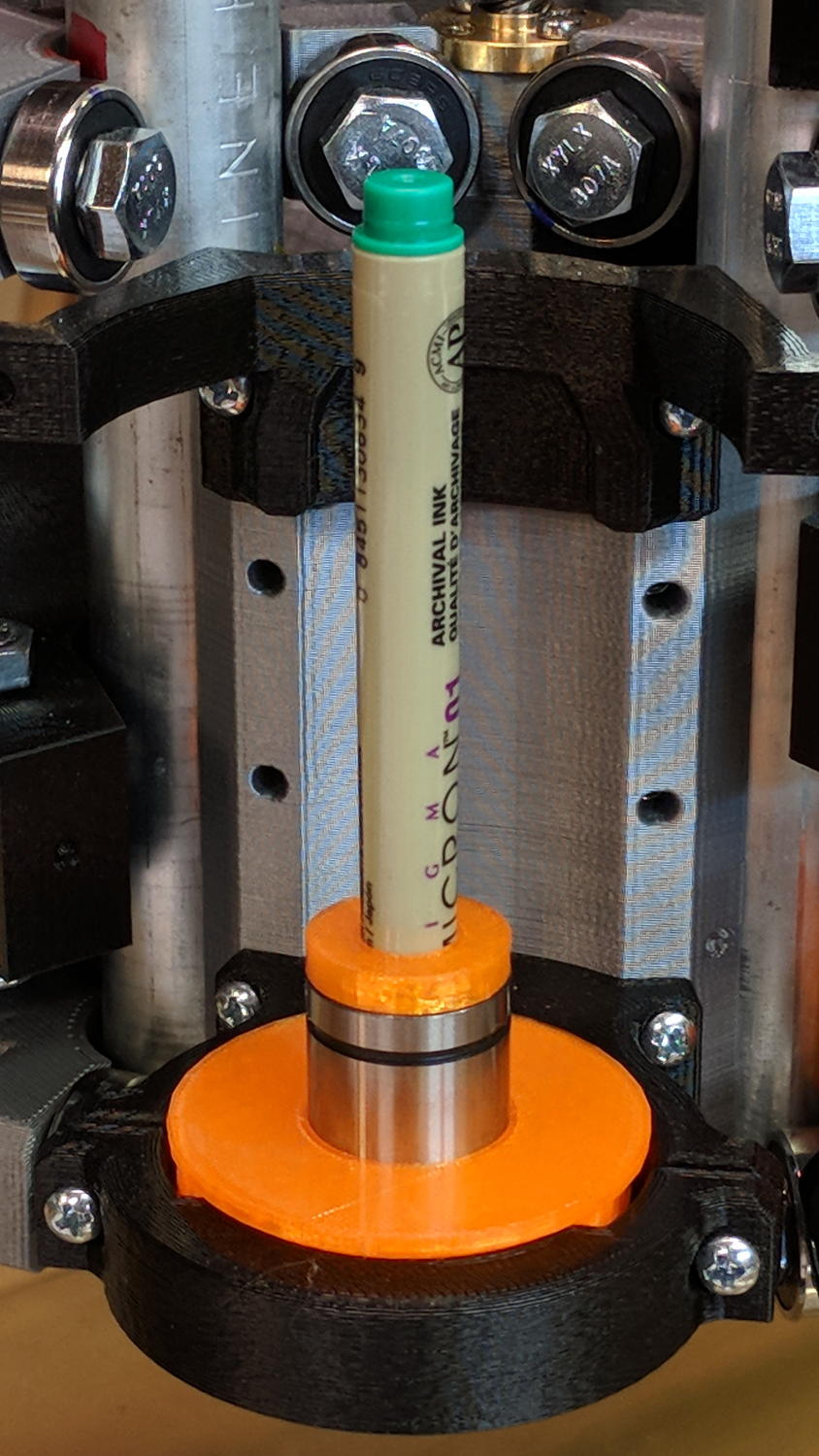
Drilling a pair of holes into a length of ground steel shaft turned it into a holder for a Sakura Micron pen:
DW660 Pen Holder – printed plastic vs ground steel
The aluminum ring epoxied to the top keeps it from falling completely through the linear bearing.
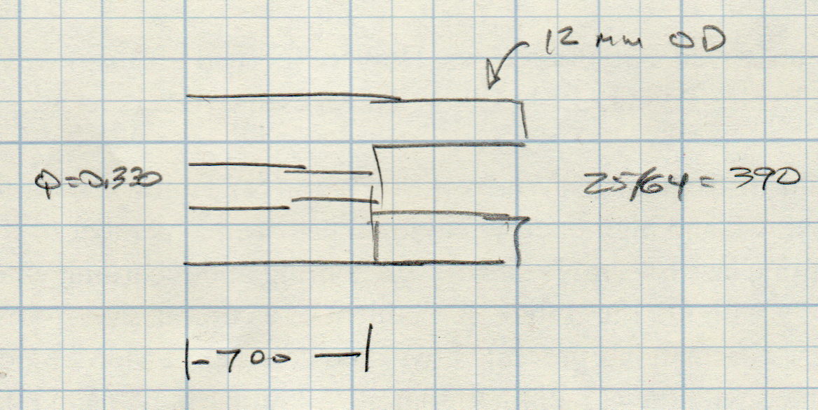
The hole sizes are the nearest inch drills matching the pen’s hard metric sizes:
Ground 12 mm rod – Sakura pen drill diameters
While I was at the lathe, I turned another layer of epoxy on the printed holder down to a consistent 11.95+ OD. It fits the bearing nearly as well as the steel shaft, although it’s not quite as smooth.
The steel version weighs about 20 g with the pen, so it applies about the same downforce on the pen nib as the HP 7475A plotter. The force varies from about 19 g as the Z axis moves upward to 23 g as it move downward, so the stiction amounts to less than 10% of the weight:
DW660 Pen Holder – ground shaft
However, the more I ponder this setup, the less I like it.
When the Z-axis moves downward and the nib hits the paper, it must decelerate the weight of the pen + holder + ballast within a fraction of a millimeter, without crushing the nib. If the pen moves downward at 3000 mm/min = 50 mm/s, stopping in 0.3 mm requires an acceleration of 4.2 m/s² and a 20 g = 2/3 oz mass will apply 0.08 N = 0.3 oz to the nib. Seems survivable, but smashing the tip a few hundred times while drawing the legends can’t possibly be good for it.
Also, the tool length probe switch trips at 60 (-ish) g, which means the pen can’t activate the switch. Adding a manual latch seems absurd, but you can get used to anything if you do it enough.
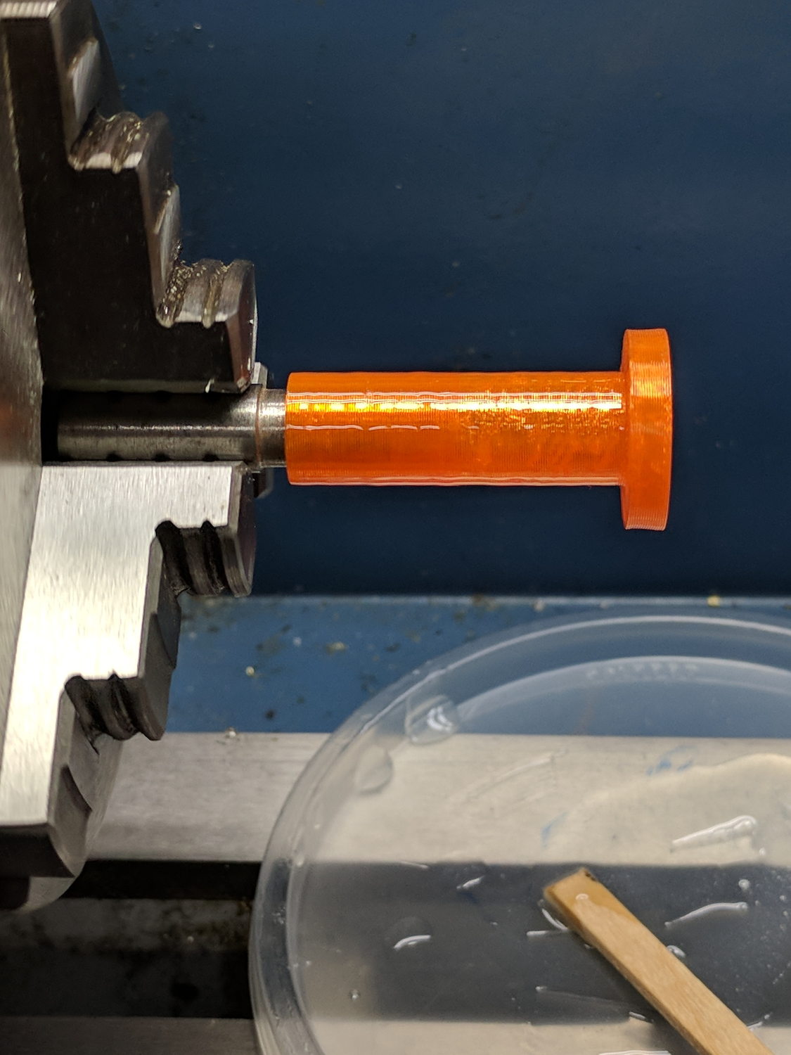
The simplest way to push a pen (or similar thing) downward with constant force may be to hold it in a linear bearing with a weight on it, so I gimmicked up a proof-of-concept. The general idea is to mount the pen so its axis coincides with the DW660 spindle, so as to have the nib trace the same path:
DW660 Pen Holder – unweighted
The puck mimics the shape of the DW660 snout closely enough to satisfy the MPCNC’s tool holder:
DW660 Pen Holder – Slic3r
The pen holder suffers from thin walls constrained by the 10 mm (-ish) pen OD and the 12 mm linear bearing ID, to the extent the slight infill variations produced by the tapered pen outline change the OD. A flock of 16 mm bearings, en route around the planet even as I type, should provide more meat.
In any event, 3D printing isn’t noted for its perfect surface finish, so I applied an epoxy layer and rotated the holder as it cured:
DW660 Pen Holder – epoxy coating
After letting it cure overnight, I ran a lathe tool along the length to knock down the high spots and set the OD to 11.9+ mm. Although the result turns out to be a surprisingly nice fit in the bearing, there’s no way epoxy can sustain the surface load required for the usual precision steel-on-steel fit.
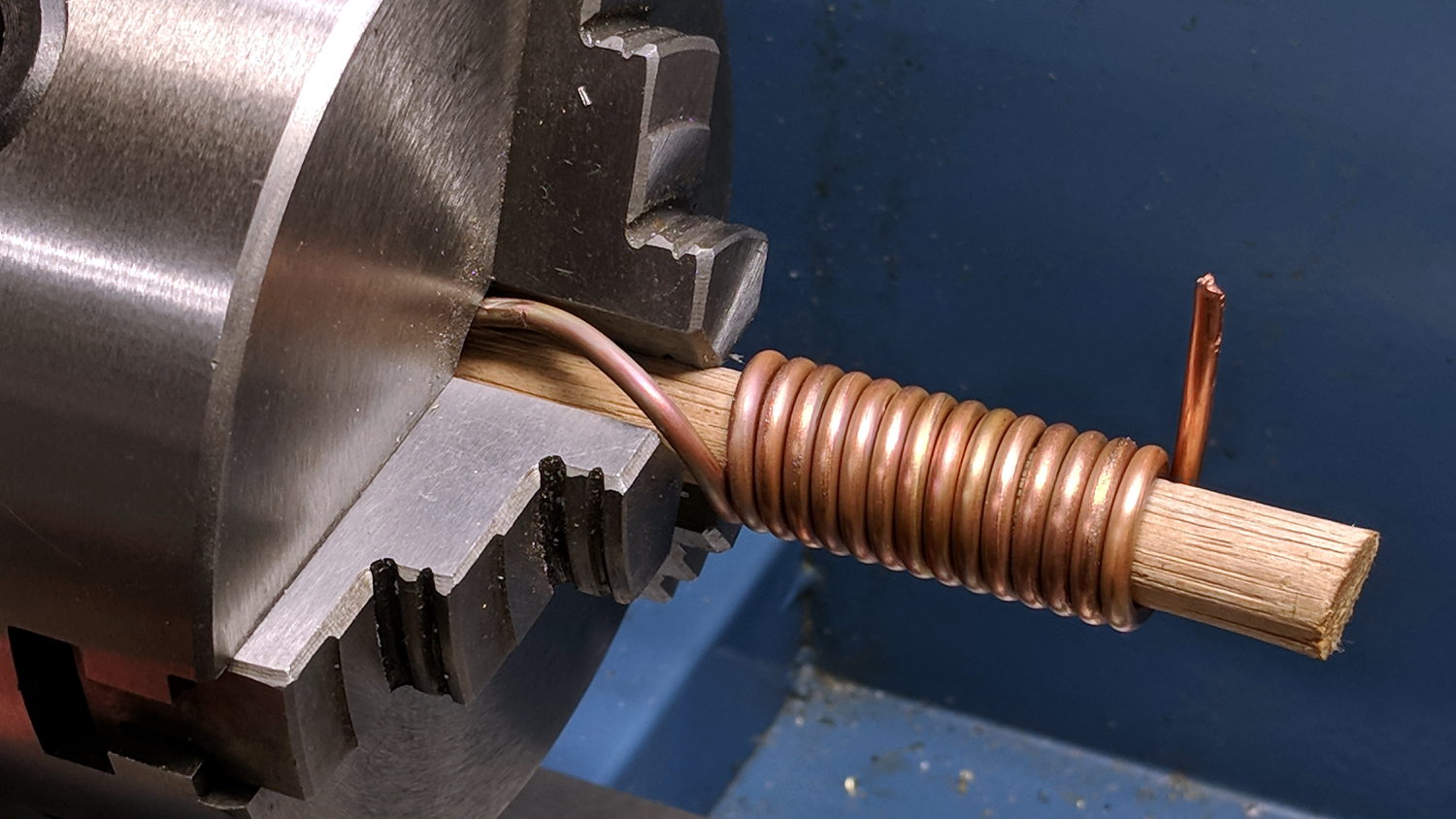
A plastic pen in a plastic holder weighs 8.3 g, which isn’t quite enough to put any force on the paper. Copper weighs 9 g/cm³ = 9 mg/mm³ and 10 AWG wire is 2.54 mm OD = 5 mm², so it’s 45 mg/mm: to get 20 g, chop off 450 mm of wire.
I chopped off a bit more than that, straightened it, annealed it, and wound it around a random contestant from the Bucket o’ Sticks with an OD just over the pen OD:
DW660 Pen Holder – copper weight forming
The helix is 13.5 mm down the middle of the turns and 14 turns long (trimmed of the tail going into the chuck and fudging the tail sticking out as a partial turn), so it’s 593 mm long and should weigh 26.7 g. It actually weighs 27.6 g: close enough.
Which is enough to overcome stiction due to the holder’s surface roughness, but the mediocre epoxy-on-balls fit allows the pen point to wander a bit too much for good results.
The prospect of poking precise holes into 16 mm drill rod seems daunting, but, based on what I see here, it will produce much better results: rapid prototyping FTW!
This file contains hidden or bidirectional Unicode text that may be interpreted or compiled differently than what appears below. To review, open the file in an editor that reveals hidden Unicode characters.
Learn more about bidirectional Unicode characters
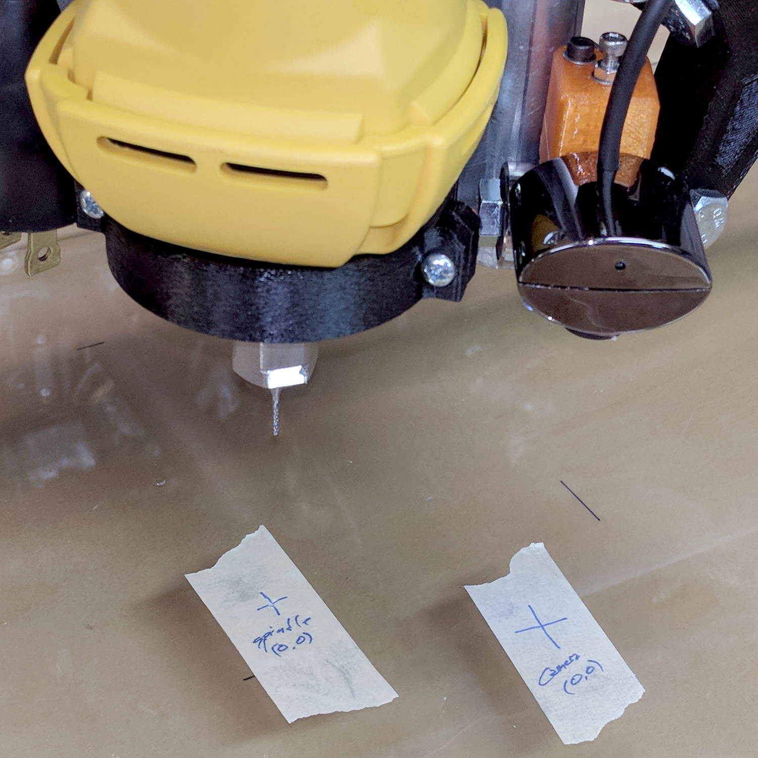
Adding a lock screw to the camera mount stabilized the camera-to-spindle offset enough to make calibration meaningful. Mark the spot directly under the camera:
bCNC – Camera – hot glue align
Then mark the spot directly under the spindle, perhaps by poking a small cutter into the tape, measure the XY distances between the two center points, and use bCNC’s camera registration process to set the camera offset.
With those numbers in place, switching to the tool view (the green button with the end mill to the right in the ribbon bar) puts the camera at the spindle location:
bCNC – Spindle – hot glue align
The view from outside shows the relation between those two pieces of tape:
MPCNC – USB camera-to-spindle alignment
Now I can align the camera view to a fixture position and be (reasonably) sure the spindle will automagically align to the same XY coordinate when I switch to the “tool” view. Seems to work well in preliminary tests, anyhow.
It turned out the previous version of the USB camera mount lacked sufficient griptivity to hold the ball’s position against even moderate bumps, so the upper “half” is now tall enough to hold a lock screw directly over the ball:
MPCNC – USB Camera mount – lock screw – Slic3r
It doesn’t look much different:
MPCNC – USB Camera Mount – lock screw
A view from the other side:
USB Camera – lock screw mount
The previous iterations used Genuine 3M foam tape, which seemed too flexy for comfort. This one sits on a bed of hot melt glue and is absolutely rigid. We’ll see how long it survives.
Tightening the cap screw requires needle-nose pliers, because the whole affair has no room for a hex key.
This file contains hidden or bidirectional Unicode text that may be interpreted or compiled differently than what appears below. To review, open the file in an editor that reveals hidden Unicode characters.
Learn more about bidirectional Unicode characters
The force increases linearly at 30 g/mm up to the trip point, drops by maybe 16 grams, then increases linearly again.
Obviously, the “constant” applies only to switches on MBI-style endstops in the lot I happen to have, but given the ubiquity of parts from the usual eBay sellers, any identical lever switches may have the same “constant”:
Endstop lever switch – detail
Your mileage will vary, fer shure.
Poking a pen into a similar switch used as a tool setter means the Z-axis coordinate of the trip point will depend on the opposing springs. That’s unlike the situation with a cutter mounted in the DW660 spindle, which (by definition) shouldn’t move in response to the pressure from a little bitty switch.
Eyeballing the graph, the switch travels 2.2 mm to the trip point, where it exerts 64 g of force. The pen holder opposes that force and therefore deflects (64 g) / (100 g/mm) = 0.64 mm just before the switch trips: the trip point will be the same as with a rigid tool, but the tool’s Z axis coordinate will be 0.64 mm lower.
I’d been touching off pens in the springy holder, with enough pressure to draw a decent line. Setting Z=0 with the holder deflected upward by 0.3 mm means the pen first touches the height probe at Z=+0.3 and the switch trips at Z=-0.3 mm (-ish), making the force on the paper 60 g, rather than the 30 g I expected.
I think the pen plots worked out pretty well, despite not getting the numbers and, thus, pen positions, quite right.
A long long time ago, I conjured a short bench for our Larval Engineer from a pair of junked folding-table legs and a truly hideous mid-50s Genuine Formica countertop salvaged from the kitchen refurbishment:
Bench Leg – overview
Most recently, it held a pile of test equipment and random stuff next to the MPCNC, whereupon the welds holding the tube with the feet to one of the vertical tubes on the far end failed. It wasn’t in the critical path, so I broke the welds on the other tube, propped the vertical tubes on wood blocks, and continued the mission. Having finally finished those measurements, I could clear off the bench and repair the legs.
I no longer have my welding gear and, in any event, it’s still winter outside, so a low-excitement repair seemed in order: drill suitable holes into the leg crosspiece, make threaded inserts for the tubes, and join them with 3/8-16 bolts.
So, we begin.
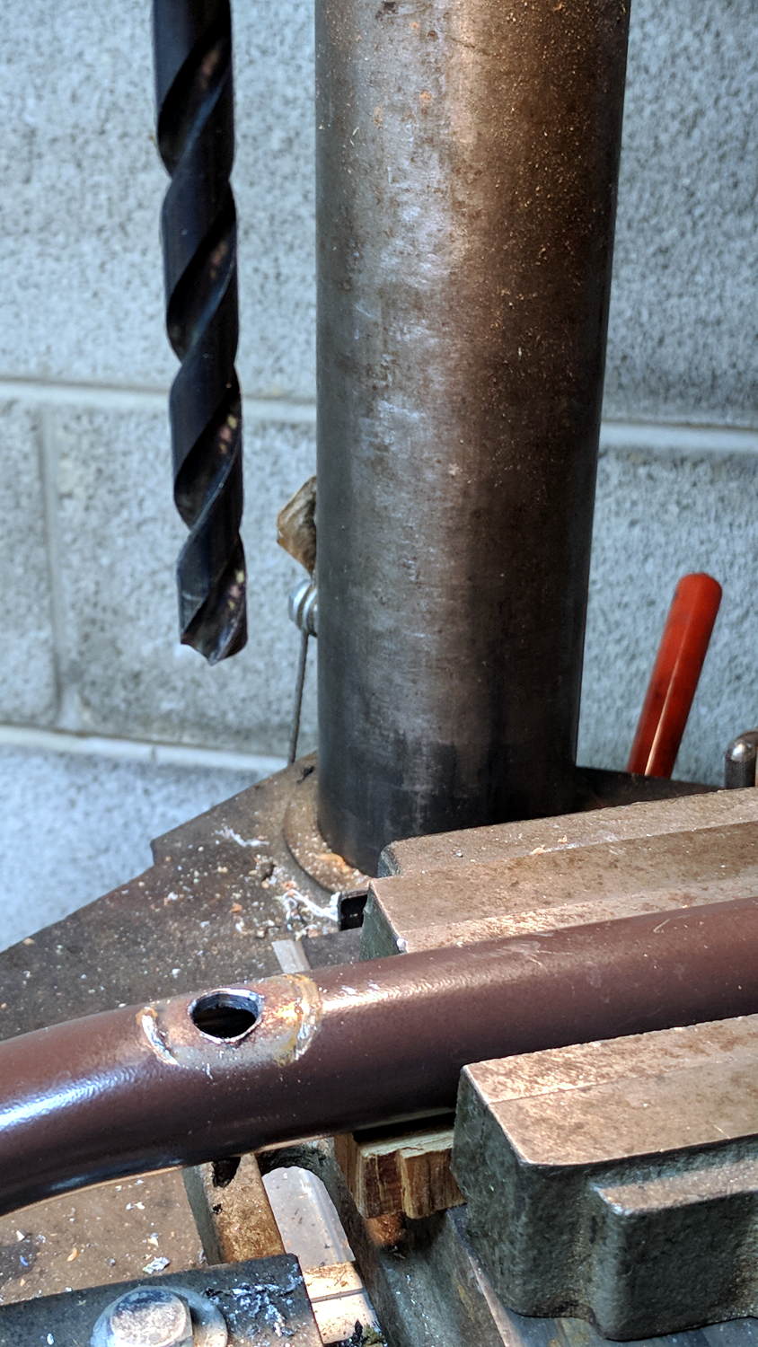
File the broken welds off the foot tube, align it in the drill press vice (where it barely fits!), center drill to make a pilot hole, then poke a 3/8 inch drill completely through to line up both holes:
Bench Leg – through drilling
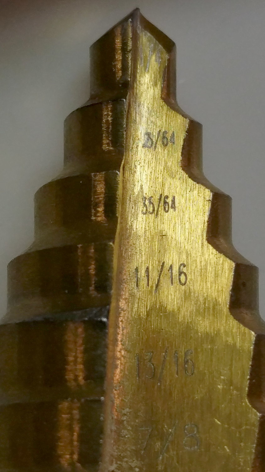
By the Universal Law of the Conservation of Perversity, a 3/8 inch bolt didn’t quite fit the 3/8 inch hole, so I embiggened the holes with a step drill:
Bench Leg – step-drilling to size
The step drill obviously has hard metric diameters labeled as weird inch sizes:
Quasi-inch step drill
I can’t read the second step, either, but it’s apparently 25/64 inch = 9.8 mm, which is just enough over 3/8 inch = 9.5 mm to be useful. The next step is 14 mm = 35/64 inch, so the drill is a bit of a lump.
The leg tubes were a hair over 0.9 inch ID and not particularly round. Tolerances being slack, slice a bit more than two inches off a 1 inch OD aluminum rod:
Bench Leg – sawing rod stock
I wanted more than one diameter in the tubes, but the bolts in my stash topped out at 2 inches and, really, an inch of aluminum won’t go anywhere.
Clean up one end of the rod to 0.9 inch OD, flip, and center drill:
Bench Leg – center drilling insert
Obviously, surface finish and concentricity aren’t critical, but the cleaned-up OD of the left end lined up at barely perceptible mismatch with the (yet to be done) right end.
Sunder in twain:
Bench Leg – sawing leg inserts
Betcha you can’t spot the junction between the two ODs, either.
Drill 3/8 inch through, then discover you (well, I) have neither a drill big enough nor a boring bar small enough to embiggen one end of the hole for a nasty interference fit against the tips of a 3/8 inch hex nut.
Once again, a step drill to the rescue:
Bench Leg – step-drilling insert
Because it’s a step drill, the counterbore isn’t quite deep enough for the whole nut, so turn the nut to fit the recess left by the drill:
Bench Leg – nut shaping
Put a bolt through the insert as a guide, spin the nut on, backstop the insert with a machinist’s parallel jaw clamp (loose, just to give the head somewhere to go), line ’em up, and mash the nut into place with the bench vise:
Bench Leg – nut pressed in place
Clean up the broken welds with a rat tail file, hammer the inserts into the tubes:
Bench Leg – insert installed
Which, as I expected, rounded them nicely while producing an absolutely solid, ain’t gonna work loose, dry joint.
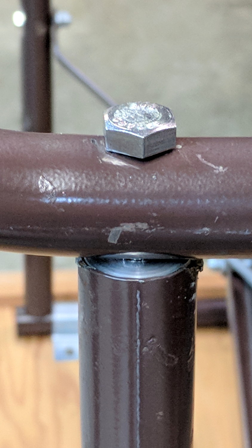
Add threadlocker to the bolts and it’s all good:
Bench Leg – repaired
Stipulated: butt-ugly.
Tell me you’d have fish-mouthed those inserts just for pretty, after noting the factory didn’t bother fishmouthing the vertical tubes before welding them in place.
But it was good for generous dose of Quality Shop Time!
The hole fits a 25 mm fan, but the thing runs cool enough it should survive without forced air; think of it as a contingency. Mounting the case on standoffs seems like a Good Idea, however, as the bottom plate includes many vent slots for Good Circulation.
The top plate builds upside-down, so I had Slic3r add teeny support plugs inside the recessed screw holes. I think button-head screws would fit neatly in the recesses, but we’re obviously not in this for the looks.
The tiny white stud is a Reset switch hot-melt glued into the slot. I plan to just turn off the AC power after shutting the RPi down, so a power-on will suffice as a reset.