The Smell of Molten Projects in the Morning

Ed Nisley's Blog: Shop notes, electronics, firmware, machinery, 3D printing, laser cuttery, and curiosities. Contents: 100% human thinking, 0% AI slop.

Tag: MPCNC

Pimping and using a Mostly Printed CNC Machine

  • MPCNC: Power Supply Brick Mount

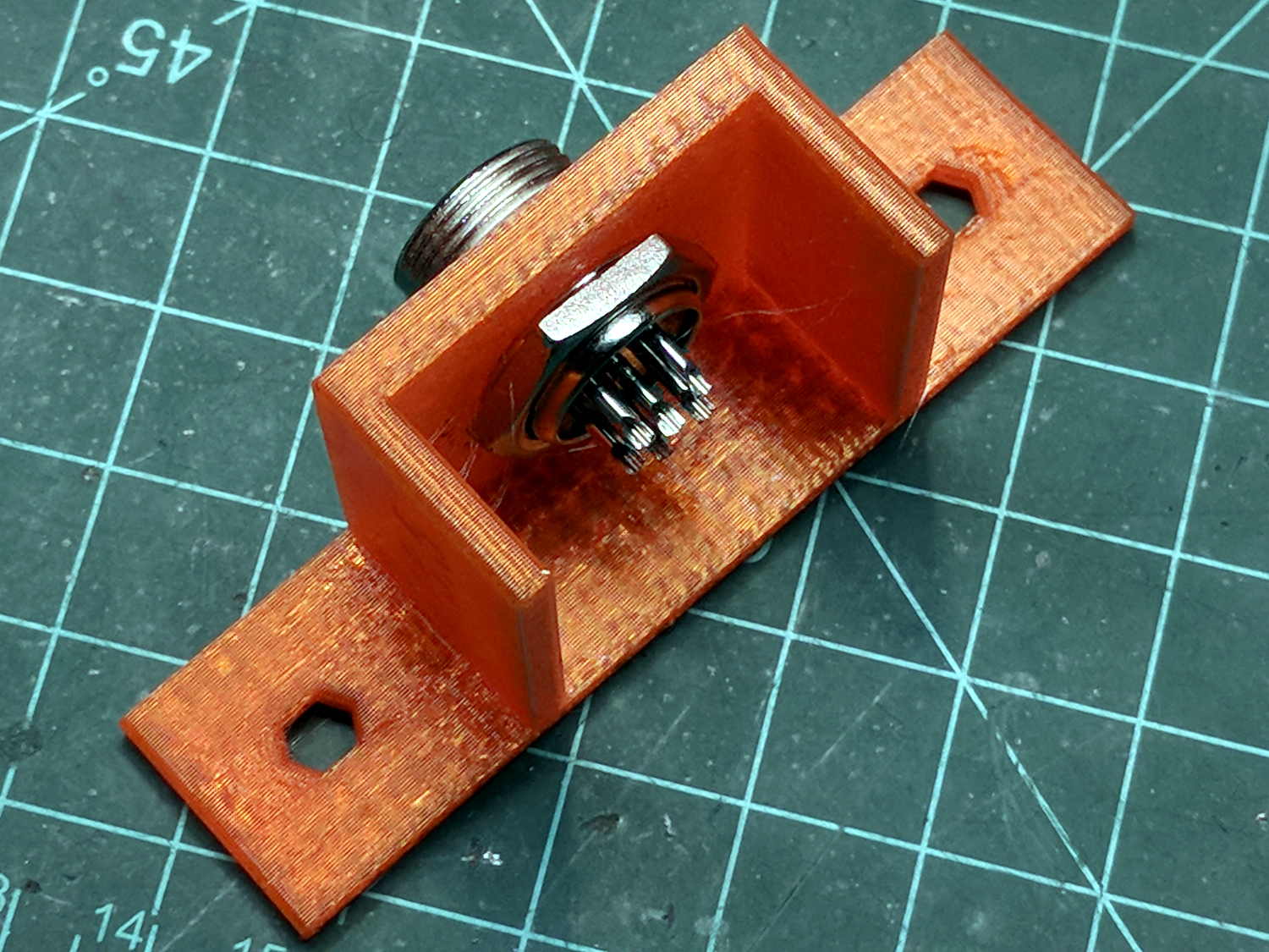
    A laptop-style power brick supplies 24 V for the MPCNC’s stepper motors, but I didn’t want it wandering around on the Basement Laboratory floor and getting in trouble, so a pair of brackets seemed in order:

    Power Supply Brick Mount - trial fit
    Power Supply Brick Mount – trial fit

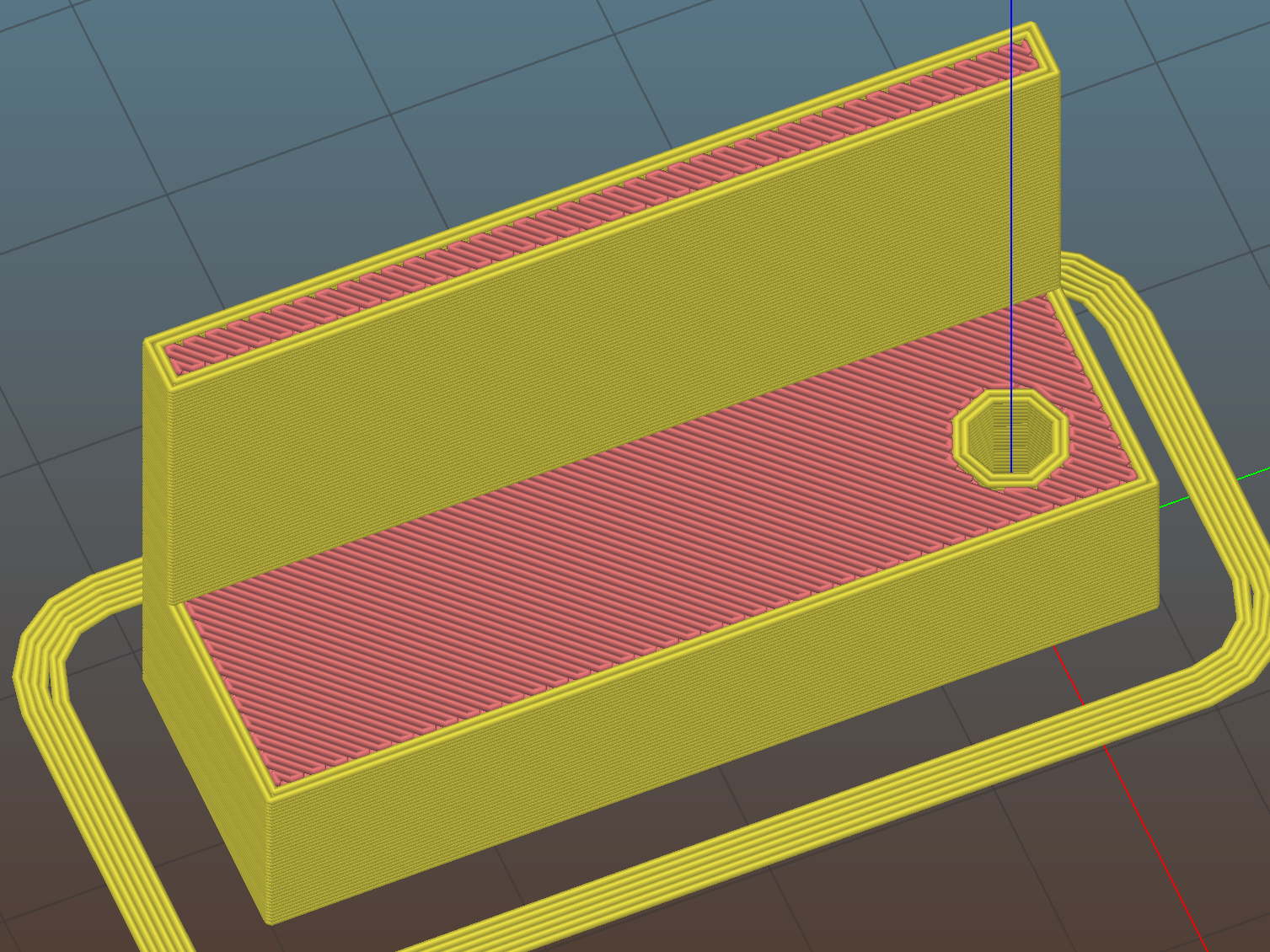
    They build flat on their backs to avoid support material:

    Power Supply Brick Mount - Slic3r
    Power Supply Brick Mount – Slic3r

    The nicely rounded corners produce a very thin line of plastic on the first layer, so the model now has thicker base plates to improve the situation. A set of mouse ears would keep the tips pasted to the glass.

    The OpenSCAD source code as a GitHub Gist:

    // Power Supply Brick brackets
    // Ed Nisley KE4ZNU 2018-02-26
    Layout = "Show";
    //– Extrusion parameters
    ThreadThick = 0.25;
    ThreadWidth = 0.4;
    HoleWindage = 0.3; // enlarge hole dia by this amount
    function IntegerMultiple(Size,Unit) = Unit * ceil(Size / Unit);
    Protrusion = 0.1; // make holes look good and joints intersect properly
    //– Useful sizes
    inch = 25.4;
    Tap10_32 = 0.159 * inch;
    Clear10_32 = 0.190 * inch;
    Head10_32 = 0.373 * inch;
    Head10_32Thick = 0.110 * inch;
    Nut10_32Dia = 0.433 * inch;
    Nut10_32Thick = 0.130 * inch;
    ID = 0;
    OD = 1;
    LENGTH = 2;
    //– Bracket Dimensions
    Brick = [170.0,66.0,40.0]; // overall size, add details in module
    Socket = [30.0,24.0]; // IEC power socket
    Cable = [6.0,15.0]; // DC output cable ID=wire OD=strain relief
    WallThick = 3.0; // default wall thickness
    BaseThick = 4.0;
    Screw = [5.1,10.0,3.0]; // screw size, more-or-less 10-32, OD & LENGTH for head
    NumSides = 3*4;
    //———————-
    // Useful routines
    module PolyCyl(Dia,Height,ForceSides=0) { // based on nophead's polyholes
    Sides = (ForceSides != 0) ? ForceSides : (ceil(Dia) + 2);
    FixDia = Dia / cos(180/Sides);
    cylinder(r=(FixDia + HoleWindage)/2,
    h=Height,
    $fn=Sides);
    }
    //———————-
    // Models
    module BrickMount(End="Both") {
    difference() {
    union() {
    hull() // main block
    for (i=[-1,1], j=[-1,1], k=[0,1])
    translate([i*(Brick.x/2 + WallThick – WallThick),
    j*(Brick.y/2 + WallThick – WallThick),
    k*(Brick.z + WallThick – WallThick)])
    sphere(r=WallThick,$fn=NumSides);
    hull() // screw flanges
    for (i=[-1,1], j=[-1,1])
    translate([i*(Brick.x/2 + WallThick – BaseThick),
    j*(Brick.y/2 + WallThick + 2*Screw[OD] – BaseThick),
    0])
    sphere(r=BaseThick,$fn=NumSides);
    }
    for (i=[-1,1], j=[-1,1]) // remove screw holes
    translate([i*(Brick.x/2 + WallThick – Screw[OD]),
    j*(Brick.y/2 + WallThick + Screw[OD]),
    -Protrusion])
    rotate(180/6)
    PolyCyl(Screw[ID],2*WallThick,6);
    translate([0,0,Brick.z/2]) // remove center part to leave ends
    cube([(Brick.x + 2*WallThick – 4*Screw[OD]),2*Brick.y,2*Brick.z],center=true);
    if (End == "Socket")
    translate([Brick.x/2,0,Brick.z/2]) // remove cable end to leave socket
    cube([(Brick.x + 2*WallThick – 4*Screw[OD]),2*Brick.y,2*Brick.z],center=true);
    if (End == "Cable")
    translate([-Brick.x/2,0,Brick.z/2]) // remove socket end to leave cable
    cube([(Brick.x + 2*WallThick – 4*Screw[OD]),2*Brick.y,2*Brick.z],center=true);
    translate([0,0,Brick.z/2 – Protrusion/2]) // remove power supply brick from interior
    cube(Brick + [0,0,Protrusion],center=true);
    translate([0,0,-Brick.z]) // remove below XY plane
    cube(2*Brick,center=true);
    translate([0,0,Brick.z/2]) // remove AC socket
    rotate([0,-90,0])
    rotate(90)
    linear_extrude(height=Brick.x,convexity=2)
    square(Socket,center=true);
    translate([0,0,Brick.z/2]) // remove DC cable
    rotate([0,90,0])
    rotate(180/8)
    PolyCyl(Cable[OD],Brick.x,8);
    translate([Brick.x/2,0,Brick.z/4 – Protrusion/2]) // … and wire slot
    cube([Brick.x,Cable[ID],Brick.z/2 + Protrusion],center=true);
    }
    }
    //———————-
    // Build it
    if (Layout == "Show")
    BrickMount("Both");
    if (Layout == "Build") {
    translate([5,0,Brick.x/2 + WallThick])
    rotate([0,90,0])
    BrickMount("Cable");
    translate([-5,0,Brick.x/2 + WallThick])
    rotate([0,-90,0])
    BrickMount("Socket");
    }
  • MPCNC: Button Box Connector Mount

    This will eventually end up on a board supporting the GRBL controller box:

    Control Box - Connector Mount - Slic3r
    Control Box – Connector Mount – Slic3r

    It’s a direct cut-n-paste descendant of the old NEMA motor mount.

    The nut threads onto the connector behind the bulkhead, so you must either wire it in place or make very sure you can feed all the terminations through the hole:

    Connector Mount
    Connector Mount

    Given the previous hairball, I think in-situ soldering has a lot to recommend it:

    GRBL - Control button wiring
    GRBL – Control button wiring

    The OpenSCAD source code as a GitHub Gist:

    // Circular connector bracket
    // Ed Nisley KE4ZNU 2018-02-22
    //– Extrusion parameters
    ThreadThick = 0.25;
    ThreadWidth = 0.4;
    HoleWindage = 0.3; // enlarge hole dia by this amount
    function IntegerMultiple(Size,Unit) = Unit * ceil(Size / Unit);
    Protrusion = 0.1; // make holes look good and joints intersect properly
    //– Useful sizes
    inch = 25.4;
    Tap10_32 = 0.159 * inch;
    Clear10_32 = 0.190 * inch;
    Head10_32 = 0.373 * inch;
    Head10_32Thick = 0.110 * inch;
    Nut10_32Dia = 0.433 * inch;
    Nut10_32Thick = 0.130 * inch;
    ID = 0;
    OD = 1;
    LENGTH = 2;
    //– Mount Sizes
    Connector = [14.6,15.5,4.0]; // connector thread; ID = dia at flat
    Screw = [5.1,10.0,3.0]; // screw size, more-or-less 10-32, OD & LENGTH for head
    MountWidth = IntegerMultiple(2*Connector[OD],ThreadWidth); // use BCD for motor clearance
    MountThick = IntegerMultiple(Connector[LENGTH],ThreadThick); // for stiffness
    WallThick = 3.0; // default wall thickness
    StandThick = IntegerMultiple(WallThick,ThreadWidth); // baseplate
    StrutThick = IntegerMultiple(WallThick,ThreadWidth); // sides holding motor mount
    UprightLength = MountWidth + 2*StrutThick;
    StandBoltHead = IntegerMultiple(Head10_32,5); // bolt head rounded up
    StandBoltOC = IntegerMultiple(UprightLength + 2*StandBoltHead,5);
    StandLength = StandBoltOC + 2*StandBoltHead;
    StandWidth = 2*StandBoltHead;
    StandBoltClear = (StandLength – UprightLength)/2; // flat around bolt head
    Recess = StandWidth – MountThick;
    echo(str("Stand Base: ",StandLength," x ",StandWidth," x ",StandThick));
    echo(str("Stand Bolt OC: ",StandBoltOC));
    echo(str("Strut Thick: ",StrutThick));
    //———————-
    // Useful routines
    module PolyCyl(Dia,Height,ForceSides=0) { // based on nophead's polyholes
    Sides = (ForceSides != 0) ? ForceSides : (ceil(Dia) + 2);
    FixDia = Dia / cos(180/Sides);
    cylinder(r=(FixDia + HoleWindage)/2,
    h=Height,
    $fn=Sides);
    }
    //———————-
    // Model
    module MotorMount() {
    difference() {
    translate([StandThick/2,0,StandWidth/2])
    cube([(MountWidth + StandThick),StandLength,StandWidth],center=true);
    translate([-Protrusion/2,0,StandWidth – (Recess – Protrusion)/2])
    cube([(MountWidth + Protrusion),MountWidth,(Recess + Protrusion)],center=true);
    translate([0,0,-Protrusion])
    PolyCyl(Connector[OD],StandWidth,4*4);
    for (j=[-1,1]) // cutouts over bolts
    translate([-Protrusion/2,
    j*((StandLength – StandBoltClear)/2 + Protrusion/2),
    StandWidth/2])
    cube([(MountWidth + Protrusion),
    (StandBoltClear + Protrusion),
    (StandWidth + 2*Protrusion)],center=true);
    for (j=[-1,1]) // stand bolt holes
    translate([(MountWidth/2 – Protrusion),j*StandBoltOC/2,StandWidth/2])
    rotate([0,90,0])
    rotate(180/6)
    PolyCyl(Clear10_32,StandThick + 2*Protrusion,6);
    translate([0,-(UprightLength/2 – ThreadWidth/2),StandWidth/2])
    rotate([90,180,0])
    linear_extrude(ThreadWidth,convexity=10)
    text(text=str(Connector[OD]),size=6,spacing=1.20,font="Arial",halign="center",valign="center");
    }
    }
    //———————-
    // Build it
    MotorMount();
  • MPCNC: Autolevel Probe, Endstop Edition

    When in doubt, use an endstop switch:

    MPCNC - Endstop Z probe - USB camera
    MPCNC – Endstop Z probe – USB camera

    The USB camera lurks in the upper right.

    Just after that picture, I clipped off the NC switch terminal so I can wire this endstop in parallel with the tool length probe. Epoxy coating to follow.

    The DW660 collet grabs a length of 1/8 inch drill rod jammed into a hole positioned to put the switch actuator directly in line with the spindle axis when it trips the switch, so as to measure a known and useful location:

    Z Axis Height Probe - MBI endstop - Slic3r
    Z Axis Height Probe – MBI endstop – Slic3r

    After mulling things over for a while, I fired up the Sherline, drilled a #54 hole in the actuator, and epoxied a 3/32 inch bearing ball in the hole:

    MPCNC - Endstop Z probe - bearing
    MPCNC – Endstop Z probe – bearing

    A #54 drill hole is half the diameter of the ball and, with a bit of luck, enough of the ball will stick through into the epoxy on the underside for a good grip:

    MPCNC - Endstop Z probe - bearing - detail
    MPCNC – Endstop Z probe – bearing – detail

    The general idea is to convert the stamped steel actuator into a single, albeit not particularly sharp, contact point that can glide over the platform / PCB / sheet-of-whatever to measure the surface. The actuator pivots as it depresses, so the ball must slide horizontally just a bit. I prefer a rod-in-tube probe poking a linear button switch, but those weren’t getting me anywhere.

    If I were really cool, I’d use a ruby ball. Maybe silicon nitride?

    The OpenSCAD source code as a GitHub Gist:

    // MPCNC Z Axis Height Probe – MBI endstop in router collet
    // Ed Nisley KE4ZNU – 2018-02-17
    Layout = "Build"; // Build, Show
    /* [Extrusion] */
    ThreadThick = 0.25; // [0.20, 0.25]
    ThreadWidth = 0.40; // [0.40]
    /* [Hidden] */
    Protrusion = 0.1; // [0.01, 0.1]
    HoleWindage = 0.2;
    inch = 25.4;
    function IntegerMultiple(Size,Unit) = Unit * ceil(Size / Unit);
    ID = 0;
    OD = 1;
    LENGTH = 2;
    //- Adjust hole diameter to make the size come out right
    module PolyCyl(Dia,Height,ForceSides=0) { // based on nophead's polyholes
    Sides = (ForceSides != 0) ? ForceSides : (ceil(Dia) + 2);
    FixDia = Dia / cos(180/Sides);
    cylinder(r=(FixDia + HoleWindage)/2,h=Height,$fn=Sides);
    }
    PCB = [40.0,1.6,16.5]; // endstop PCB, switch downward, facing parts
    Touchpoint = [4.8,4.8,-4.5]; // contact point from PCB edges, solder side
    TapeThick = 1.0; // foam mounting tape
    ShankOD = 0.125 * inch; // rod into tool collet
    ShankInsert = 3*ShankOD; // … insertion into switch holder
    WallThick = 3.0; // basic wall & floor thickness
    Mount = [PCB.x,
    (WallThick + TapeThick + Touchpoint.y) + (ShankOD/2 + WallThick),
    PCB.z + ShankInsert
    ];
    NumSides = 2*4;
    //—–
    // Define shapes
    module SwitchMount() {
    difference() {
    translate([PCB.x/2 – Touchpoint.x, // overall block
    Mount.y/2 – (ShankOD/2 + WallThick),
    (PCB.z + ShankInsert)/2])
    cube(Mount,center=true);
    translate([0,0,-Protrusion]) // collet shank hole
    PolyCyl(ShankOD,2*Mount.z,NumSides);
    translate([PCB.x/2 – Touchpoint.x, // PCB recess
    -Mount.y/2 + TapeThick + Touchpoint.y,
    PCB.z/2 – Protrusion/2])
    cube([Mount.x + 2*Protrusion,
    Mount.y,
    PCB.z + Protrusion
    ]
    ,center=true);
    }
    }
    //—–
    // Build it
    if (Layout == "Show")
    SwitchMount();
    if (Layout == "Build") {
    translate([0,0,Mount.z])
    rotate([180,0,-90])
    SwitchMount();
    }
  • MPCNC: Button Box Wiring

    The wiring hairball between the control button pendant and the Protoneer board looks like this:

    GRBL - Control button wiring
    GRBL – Control button wiring

    The as-built schematic, such as it is:

    GRBL Control button wiring - sketch
    GRBL Control button wiring – sketch

    Yes, the SSR negative output goes to the Protoneer + Power Input.

    I should drive the SSR from the Motor Enable output (in the external motor control header), rather than +5 V, to let GRBL control the motors, with a manual E-Stop override. The A4988 drivers require -Enable, so:

    • -Enable to SSR -Control input (replaces GND)
    • +5 V to BRS to SSR +Control input (as before)

    The SSR Control input draws 13 mA at 5 V, suggesting I should drive the AC SSR (for the spindle motor) from the DC SSR output, rather than paralleling the two on a single Arduino output pin.

    I belatedly recognized the E-Stop BRS as an instantiation of an SCP-001-J Keter-class anomaly; it is now appropriately labeled:

    MPCNC EStop as SCP-001-J
    MPCNC EStop as SCP-001-J

    I can attest to its effect on rational thought; a molly-guard may be required.

  • MPCNC: Autolevel Probe, Tactile Switch Edition

    So I intended to shrink the Autolevel probe with 1/8 inch drill rod and a tactile membrane switch:

    MPCNC - Simple Z probe - pogo tactile switch
    MPCNC – Simple Z probe – pogo tactile switch

    Unfortunately, it didn’t work nearly as well as I expected, because the switch membrane requires slightly less than the 180 g of pressure that pushes the P100 pogo pin entirely into its housing, leaving no overtravel worth mentioning. The membrane switch mechanism itself has much less than 1 mm of overtravel after the dome snaps, which left me with an uncomfortable feeling of impending doom.

    I managed to figure that out before completely assembling the thing, saving me a bit of time.

    The end of the pogo pin initially sported a dot of epoxy to spread the load over the switch dome:

    Pogo pin with epoxy switch-pusher drop
    Pogo pin with epoxy switch-pusher drop

    I dismantled the pogo pin to see whether I could substitute a more forceful spring how it worked. As expected, a teeny spring drives the probe up against a trio of indentations in the brass housing. I didn’t expect the probe to have such an intricate shape, but it’s obvious in retrospect.

    The OpenSCAD code for the housing required minimal tweakage from the larger version, so it’s not worth immortalizing.

  • MPCNC: USB Camera Mount

    The bCNC doc shows a camera mount made from acrylic and aluminum, but the MPCNC tool carrier lacks anywhere to secure such a thing. The camera should be reasonably close to the spindle axis, high enough to clear the work, and stable enough to hold its alignment. There’s a tiny flat spot next to the outer-lower Z-axis bearing supports (along the bottom of the picture), so that’s where it must go:

    MPCNC - Central Assembly - detail
    MPCNC – Central Assembly – detail

    At least for now, anyway.

    The USB camera originally mounted on a spring clip, with a 10 mm ball at the end of a 6 mm OD × 6 mm long stalk. Because we live in the future, building a matching ball socket isn’t particularly difficult:

    MPCNC - USB Camera mount - Slic3r
    MPCNC – USB Camera mount – Slic3r

    3D printing FTW!

    The stalk opening slants downward by 5°, because the camera PCB isn’t quite aligned with the stalk and I couldn’t get the first version to aim the lens directly downward.

    A pair of brass inserts anchor the two M3 SHCS. The clamping force seems barely adequate to the task, but I’ll wait to see what else I don’t like before complexicating the situation.

    A square of Genuine 3M sticky foam tape holds the mount to the MPCNC beside the DeWalt DW660 spindle:

    MPCNC USB Camera - installed
    MPCNC USB Camera – installed

    The MPCNC bearing bracket doesn’t provide much surface area for the foam and it’s a bit more flexy than I’d like, but good practice probably requires verifying the spindle-to-camera offset before trusting the results, so we’ll see how it works.

    The initial camera alignment consists of putting a mirror flat on the (pretty much level) platform:

    MPCNC USB Camera - mirror alignment
    MPCNC USB Camera – mirror alignment

    Then you adjust the camera so its lens looks squarely at itself in the middle of the image:

    bCNC - Camera - Mirror Alignment - first mount
    bCNC – Camera – Mirror Alignment – first mount

    The picture shows the camera aligned left-to-right (because the ball can rotate around the shaft axis), but the first mount didn’t allow the stalk to have enough downward tilt to center the lens image on the horizontal crosshair, thus the -5° tilt appearing in the second version.

    With the camera lens centered on its reflection, you know the optical axis is perpendicular to the mirror. Because the mirror is flat on the bench, the optical axis must be perpendicular to the bench, which is parallel to the XY plane. Because we assume the MPCNC Z-axis moves perpendicular to the bench = XY plane, the distance between the spindle axis and the camera axis will remain constant, regardless of the Z-axis position.

    Seems workable to me.

    The OpenSCAD program as a GitHub Gist:

    // MPCNC USB Camera Mount
    // Ed Nisley KE4ZNU – 2018-02-16
    Layout = "Build"; // Build, Show, Mount
    /* [Extrusion] */
    ThreadThick = 0.25; // [0.20, 0.25]
    ThreadWidth = 0.40; // [0.40]
    /* [Hidden] */
    Protrusion = 0.1; // [0.01, 0.1]
    HoleWindage = 0.2;
    inch = 25.4;
    function IntegerMultiple(Size,Unit) = Unit * ceil(Size / Unit);
    ID = 0;
    OD = 1;
    LENGTH = 2;
    //- Adjust hole diameter to make the size come out right
    module PolyCyl(Dia,Height,ForceSides=0) { // based on nophead's polyholes
    Sides = (ForceSides != 0) ? ForceSides : (ceil(Dia) + 2);
    FixDia = Dia / cos(180/Sides);
    cylinder(r=(FixDia + HoleWindage)/2,h=Height,$fn=Sides);
    }
    //- Dimensions
    CameraStalk = [6.0 + 1.0,10.0 + HoleWindage,4.0]; // stalk OD, ball OD, stalk length
    CameraAngle = -5; // stalk tilt, negative = downward
    MountBlock = [24.0,20.0,CameraStalk[OD] + 7.0]; // cube to hold ball, stick to MPCNC frame
    Insert = [3.0,4.4,4.5]; // brass insert
    NumSides = 6*4;
    //—–
    // Define shapes
    // Camera mount, enlongated for E-Z differencing
    // Origin at center of ball, stalk along +X
    module Camera() {
    union() {
    sphere(d=CameraStalk[OD] + HoleWindage,$fn=NumSides);
    rotate([0,90 – CameraAngle,0])
    PolyCyl(CameraStalk[ID],3*CameraStalk[LENGTH],NumSides);
    }
    }
    module Mount(Half="All") {
    Rounding = 2.0;
    ZShift =
    (Half == "Upper") ? -MountBlock.z/2 :
    (Half == "Lower") ? MountBlock.z/2 :
    2*MountBlock.z;
    difference() {
    hull()
    for (i=[-1,1], j=[-1,1], k=[-1,1])
    translate([i*(MountBlock.x – Rounding)/2,j*(MountBlock.y – Rounding)/2,k*(MountBlock.z – Rounding)/2])
    sphere(d=Rounding,$fn=3*4);
    for (j=[-1,1])
    translate([-MountBlock.x/4,j*MountBlock.y/4,-(MountBlock.z/2 + Protrusion)]) {
    PolyCyl(Insert[OD],Insert[LENGTH] + Protrusion,6);
    PolyCyl(Insert[ID],2*MountBlock.z,6);
    }
    translate([MountBlock.x/2 – (CameraStalk[OD]/2 + CameraStalk[LENGTH]),0,0])
    Camera();
    translate([0,0,ZShift])
    cube([2*MountBlock.x,2*MountBlock.y,MountBlock.z],center=true);
    }
    }
    //—–
    // Build it
    if (Layout == "Mount")
    Mount();
    if (Layout == "Show")
    Mount();
    if (Layout == "Build") {
    translate([0,0.75*MountBlock.y,MountBlock.z/2])
    rotate([180,0,0])
    Mount("Upper");
    translate([0,-0.75*MountBlock.y,MountBlock.z/2])
    rotate([0,0,0])
    Mount("Lower");}
  • USB Camera Re-Cabling

    The bCNC doc shows how to use a USB camera for XY alignment and I want to try it out. The Box o’ USB Cameras emitted a likely candidate with a focusing lens, six (!) white LEDs, and a ball mount attached to an aggressive spring clip, but its thick USB cable included a lumpy brightness pot for the LEDs and sprouted a mic plug (apparently, it predated cheap USB audio):

    USB Camera - OEM wiring
    USB Camera – OEM wiring

    The Box o’ USB Cables emitted a surprisingly long cable amputated from some random hunk of consumer electronics.

    The LED brightness won’t need much adjustment after the first few minutes. I found a little 2 kΩ trimpot to fit the PCB holes:

    USB Camera - inside - brightness pot
    USB Camera – inside – brightness pot

    Miracle of miracles, the dial ended up almost centered behind the original mic pore. A few minutes of gentle filing embiggened the pore and moved it over the trimpot:

    USB Camera - front with brightness pot
    USB Camera – front with brightness pot

    Yeah, the hole may need a plug or tape to keep the dust out, but there’s an even bigger gap around the lens.

    It produces a 640×480 picture with pretty much the expected quality, which should suffice for its intended purpose.

    Next step: stick it somewhere on the MPCNC.