The Smell of Molten Projects in the Morning

Ed Nisley's Blog: Shop notes, electronics, firmware, machinery, 3D printing, laser cuttery, and curiosities. Contents: 100% human thinking, 0% AI slop.

Tag: MK4

Prusa Mk 4 3D printer with MMU3 feeder

  • Prusa MK4+MMU3 vs. Spool Join: Whoopsie

    Prusa MK4+MMU3 vs. Spool Join: Whoopsie

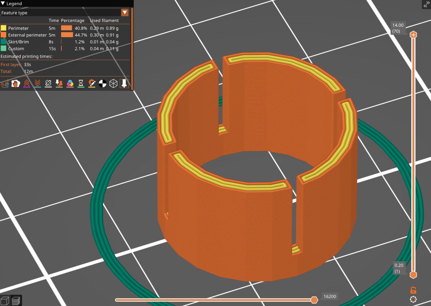
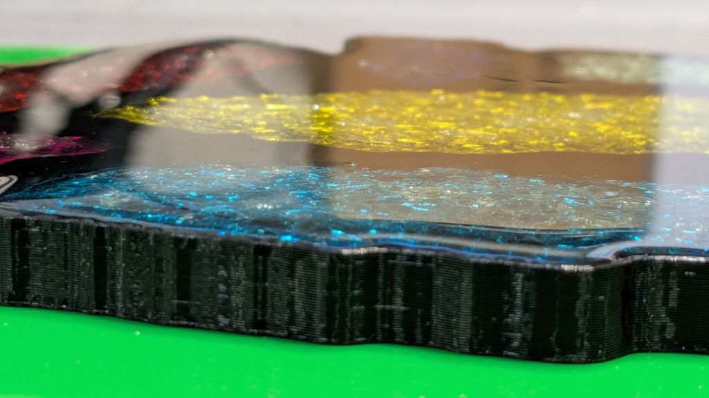
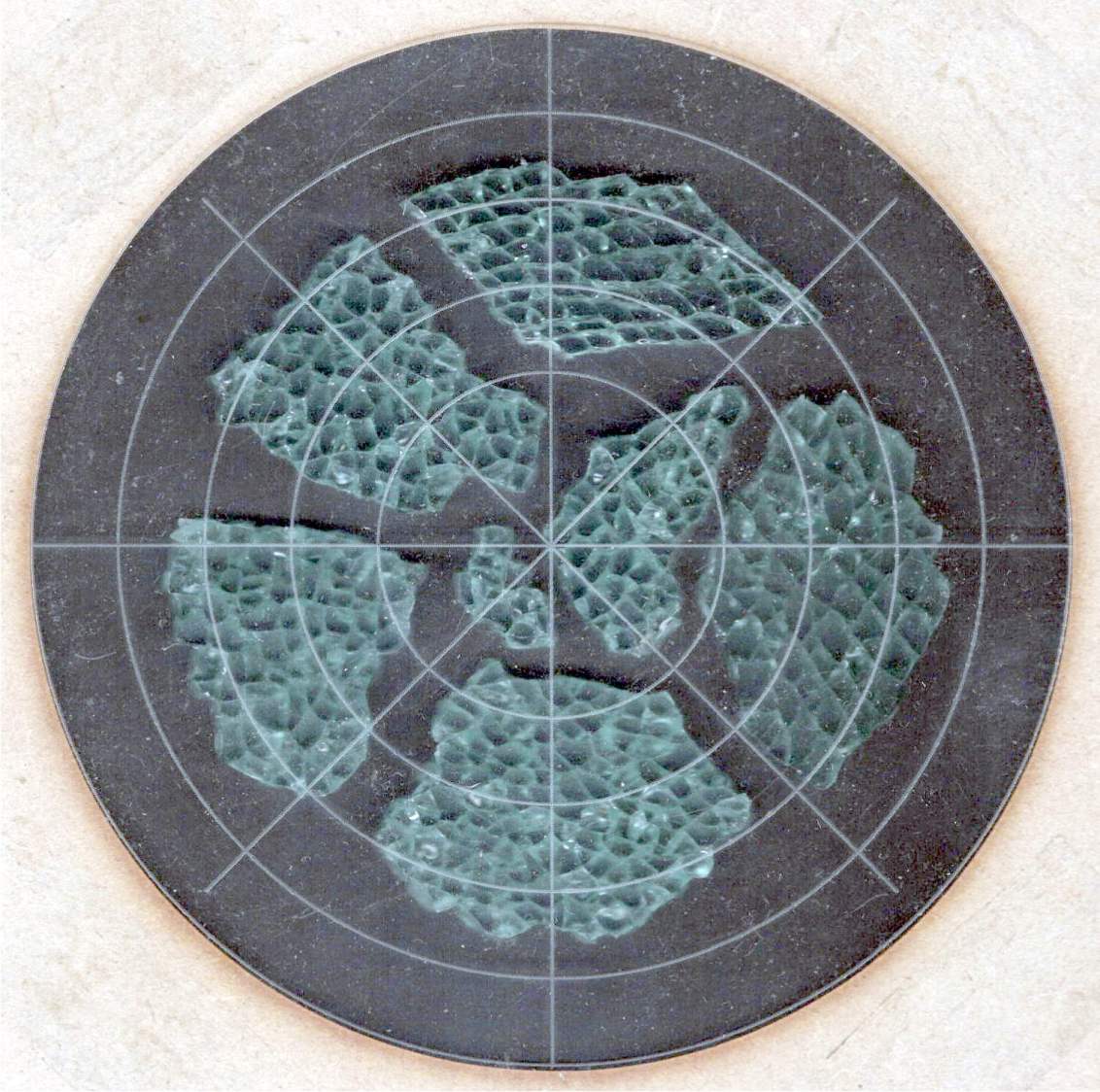
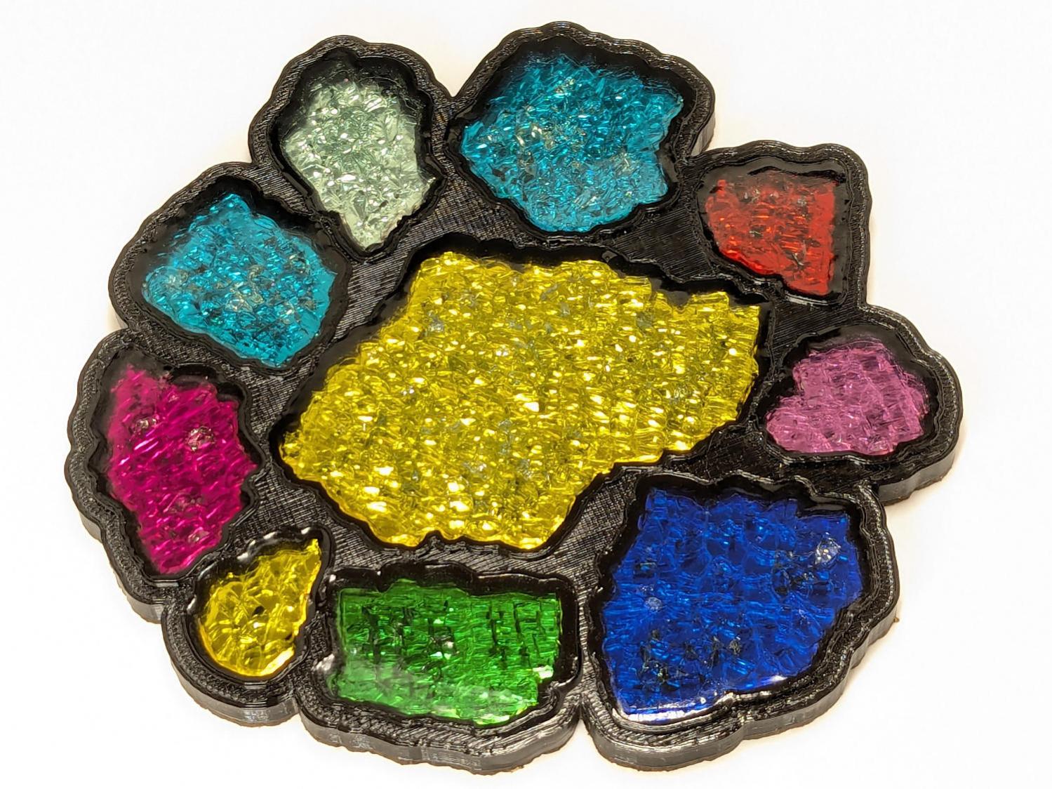
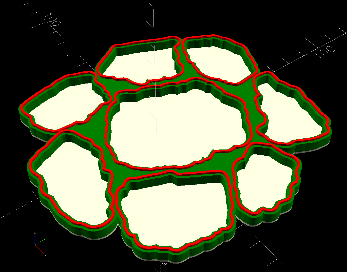
    Because nobody will ever see the Radiator Sleds, I started a batch with the tail end of the white PETG spool and set up the Spool Join function to switch to the retina-burn orange PETG when the white filament ran out.

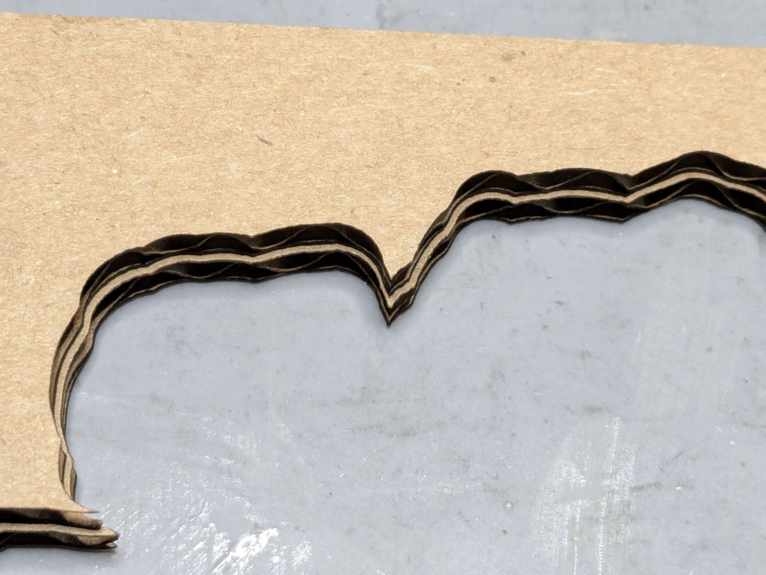
    The two colors combined nicely on that layer:

    Prusa MK4 MMU filament joining
    Prusa MK4 MMU filament joining

    Unfortunately, the Spool Join didn’t work out quite right and I had to extricate the white filament from the MMU3, then coerce the orange filament into position.

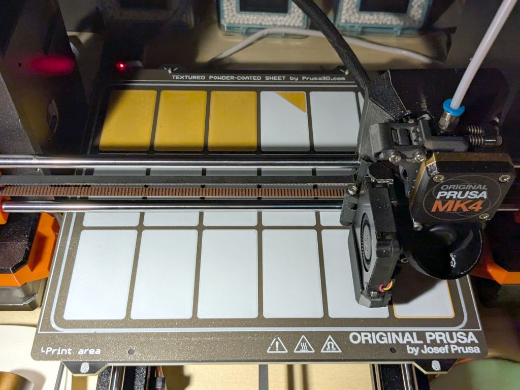
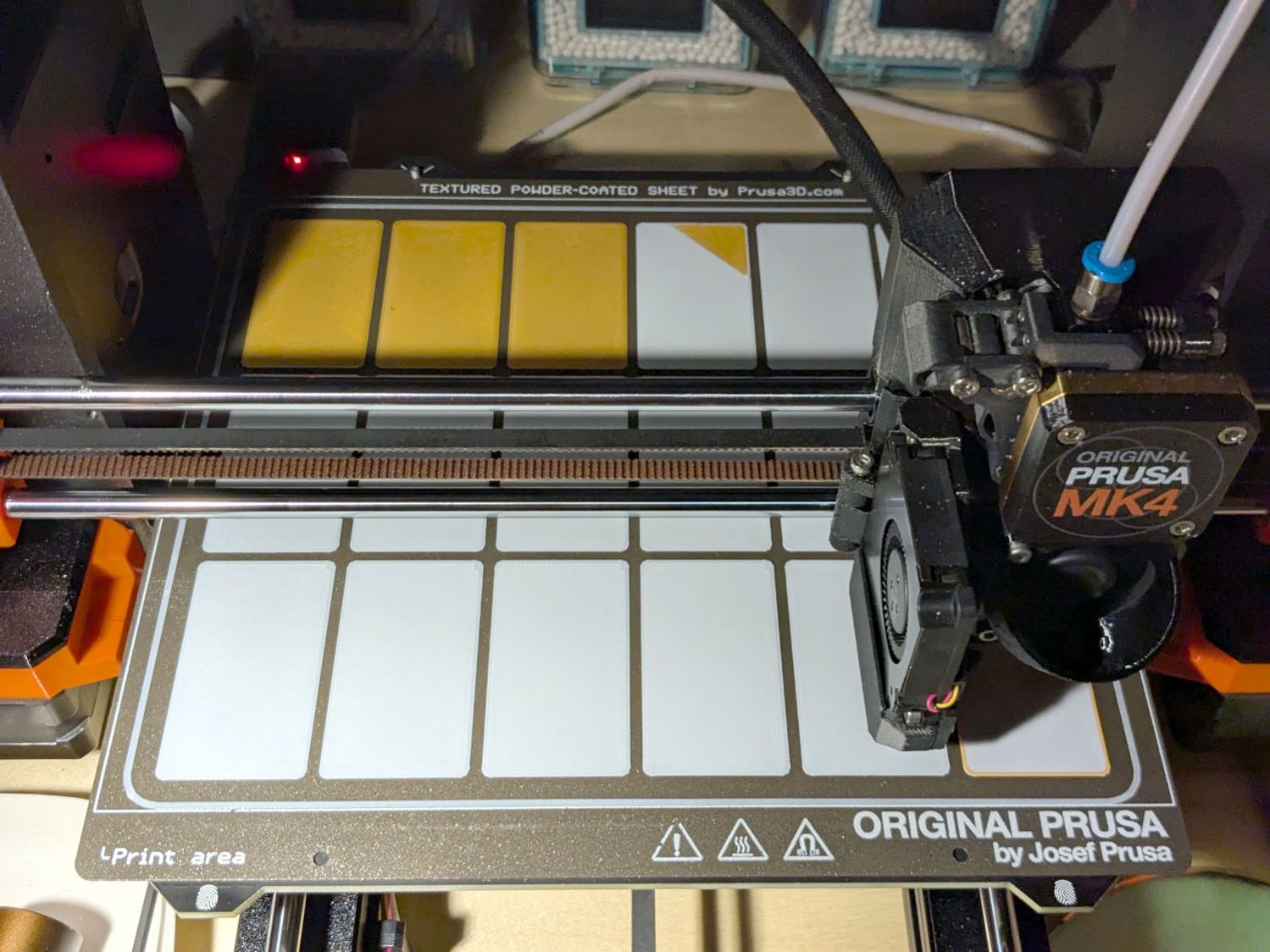
    The key section of the MMU3 looks like this:

    Prusa MK4 MMU filament joiningPrusa Mk4 MMU3 selector
    Prusa MK4 MMU filament joiningPrusa Mk4 MMU3 selector

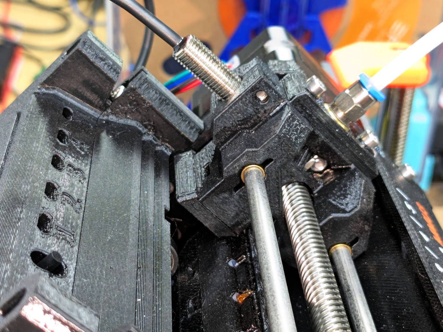
    The Selector assembly rides on the smooth rods, driven by the stepper motor on the far end of the leadscrew. It stops at one of the five filament tubes (visible to the left of the upper smooth rod, with filament tips showing), whereupon a drive gear pushes the filament into the Selector, under the FINDA sensor (the threaded fitting sticking out of the top), into the PTFE tube, down to the Nextruder, through the idler to trip the Filament Sensor, then into the extruder’s planetary drive gear.

    I think this happened:

    • The rear end of the white filament passed through the FINDA sensor
    • The MK4 reversed the Nextruder to drive the filament back into the MMU3
    • The rear end of the filament didn’t reenter its filament tube and escaped out to the side
    • The MMU3 drive gear couldn’t pull the filament backward, because the back end was misplaced
    • The Extruder planetary drive gear couldn’t pull the filament forward, because the front end was now above the gear
    • Both the FINDA and the Filament Sensor showed the filament was present, so the MK4 knew something was wrong

    Fortunately, I was watching the whole operation and could intervene.

    The MMU3 works well when the filament behaves properly, but it’s very sensitive to bends in the filament and misshapen ends. In this case, the white filament had the usual tight curve due to being would around the spool hub, which was enough to mis-align its end with the MMU3 tube while backing out.

    Trust, but verify.

  • Handlebar Grip Sleeve

    Handlebar Grip Sleeve

    Mary’s zero-mph crash loosened the starboard handlebar plug enough to let it eventually decamp for parts unknown. Its replacement, a somewhat fancier aluminum plug with an expanding cone retainer using an actual M3 nut, worked fine for the last year, but Mary recently noticed the socket head screw had worked loose.

    In the interim, I’d moved the Bafang thumb control from its original position on the crossbar to just above the rear shifter:

    Tour Easy - right handlebar control stack
    Tour Easy – right handlebar control stack

    Which moved the clamp on the shortened grip off the end of the handlebar tube, so I flipped the grip around, tightened the clamp, and installed the plug.

    Unfortunately, the grip ID is 4 mm larger than the tube ID, which meant the plug’s cone retainer was struggling to hold on in there. Perhaps the plastic cone has relaxed bit, but I figured giving it more traction would be a Good Idea™ before I declared victory:

    Handlebar Grip Sleeve - PrusaSlicer
    Handlebar Grip Sleeve – PrusaSlicer

    It’s a little plastic sleeve with slots to let it expand against the inside of the grip:

    Handlebar grip sleeve - installed
    Handlebar grip sleeve – installed

    Yes, it’s sticking out slightly; you can see the corresponding gap up inside next to the tube.

    A wrap of double-sided sticky tape glues it in place as the retainer presses it against the grip ID and a dot of low-strength Loctite should keep the screw from loosening again.

    The OpenSCAD source code:

    // Handlebar grip sleeve
    // Ed Nisley - KE4ZNU
    // 2025-10-25
    
    include <BOSL2/std.scad>
    
    /* [Hidden] */
    
    ID = 0;
    OD = 1;
    LENGTH = 2;
    
    HoleWindage = 0.2;
    Protrusion = 0.1;
    NumSides = 3*2*4;
    
    $fn=NumSides;
    
    Sleeve = [18.5,22.0,14.0];
    Kerf = 1.0;
    
      difference() {
        tube(Sleeve[LENGTH],id=Sleeve[ID],od=Sleeve[OD],anchor=BOTTOM);
        for (a=[0,90])
          zrot(a)
            up(Sleeve[LENGTH]/4)
              cuboid([2*Sleeve[OD],Kerf,Sleeve[LENGTH]],anchor=BOTTOM);
      }


    That was easy …

  • 3D Printed Smashed Glass Coasters: Being Epoxy-Tight

    3D Printed Smashed Glass Coasters: Being Epoxy-Tight

    Each of the glass fragments in a 3D printed coaster sits atop a metallized paper reflector in its own recess and gets covered with epoxy:

    Printed Coasters - epoxy fill
    Printed Coasters – epoxy fill

    That’s an early printed coaster with the epoxy pool covering the entire surface. Putting a rim around each fragment to form separate pools works better.

    Assuming I do a tidy job of filling the recesses, this process worked exactly as you’d expect until I printed a coaster with blue PETG-CF filament:

    Printed Coaster - Set C - oblique
    Printed Coaster – Set C – oblique

    Other than a slightly ragged cork layer motivating me to make the cork slightly smaller and use a fixture to align it properly, the coaster looks reasonably good. However, a close inspection shows all the epoxy pools are slightly recessed below their rims.

    It turns out printing PETG-CF with an extrusion multiplier of 0.8, which I figured based on fitting threaded parts together, doesn’t fuse the threads into an epoxy-tight surface:

    Printed Coasters - PETG-CF leakage - footprint
    Printed Coasters – PETG-CF leakage – footprint

    Fortunately, I’d been working on a silicone mat that could take a joke. I managed to move the coaster to a plastic sheet and refill the drained pools, although they continued to drain while curing.

    After the epoxy cured to a rubbery texture, I scraped off the meniscus around the perimeter of the coaster, but the bottom shows it cured in a pool of its own making:

    Printed Coasters - PETG-CF leakage
    Printed Coasters – PETG-CF leakage

    The cork conceals the evidence and the result looks good enough for my simple needs:

    Smashed Glass 3D Printed Coaster - Set C - in use
    Smashed Glass 3D Printed Coaster – Set C – in use

    Memo to self: Use the correct filament preset for the job!

  • 3D Printed Smashed Glass Coasters: Cork Alignment Fixture

    3D Printed Smashed Glass Coasters: Cork Alignment Fixture

    The printed coaster frame sits on a cork base:

    Printed Coaster - inset cork
    Printed Coaster – inset cork

    A sheet of craft adhesive holds them together; stick a generous rectangle of adhesive on the cork, then cut them at the same time. However, given the irregular perimeter, it’s basically impossible (for me, anyway) to align the cork + adhesive with the printed frame.

    A single-use fixture made from corrugated cardboard make that task trivially easy:

    Printed Coaster - cork alignment fixture - detail
    Printed Coaster – cork alignment fixture – detail

    The LightBurn layout shows the cork layer and the two fixture pieces:

    The cork shape is offset 0.5 mm inward from the Perimeter shape, but I found offsetting the cardboard cut by only 0.3 mm inward produced a snug fit around the cork. The other piece of cardboard gets cut with the exact Perimeter shape and no offset, with the laser kerf providing just enough clearance for a very snug fit on the printed shape.

    Align the two pieces of cardboard by eye to match their inner shapes as shown in the picture, tape them together, and the fixture is ready. In principle, the outer edges should exactly coincide: Trust, but verify.

    Peel off the craft adhesive paper and put the cork in the bottom of the fixture. The cork comes off a roll and really wants to roll up again, making the masking tape holding it flat mandatory:

    Printed Coasters - cork alignment template
    Printed Coasters – cork alignment template

    Yes, that’s a different coaster.

    Flip the fixture over, drop the coaster in place, press firmly together, peel the tape, and pull out the finished coaster:

    Printed Coasters - white PETG finished
    Printed Coasters – white PETG finished

    The fixture goes in the recycling bin, as those fragments will never pass this way again.

  • 3D Printed Smashed Glass Coasters: Fragment Path Offsets, Simplified Version

    3D Printed Smashed Glass Coasters: Fragment Path Offsets, Simplified Version

    Rather than use Inkscape or LightBurn to generate all the offsets required to make a solid model, it’s easier to let OpenSCAD handle it:

    Printed Coaster Layout - 100 mm Set G - solid model
    Printed Coaster Layout – 100 mm Set G – solid model

    The overall process:

    • Pick some interesting fragments
    • Scan to get an image
    • Mark the fragments in GIMP
    • Create a suitable circumcircle in LightBurn
    • Use a nesting program like Deepnest to create a nice layout of the fragments within the circle
    • Create the perimeter path as an offset around all the fragments in LightBurn

    Because the fragments have irregular shapes and spacing, creating the perimeter path may also produce small snippets of orphaned geometry which must be manually selected and deleted. I also edit the path to remove very narrow channels between adjacent fragments.

    Which is why you can’t generate that path automatically:

    Printed Coaster Layout - 100 mm Set G - LightBurn perimeter geometry
    Printed Coaster Layout – 100 mm Set G – LightBurn perimeter geometry

    Because LightBurn doesn’t have the ability to name the various paths, the next step requires Inkscape. After importing the LightBurn paths saved as an SVG, group all the fragments and name the group Fragments, then name the perimeter path Perimeter:

    Printed Coaster Layout - 100 mm Set G - Inkscape layer and IDs
    Printed Coaster Layout – 100 mm Set G – Inkscape layer and IDs

    Inkscape still crashes unpredictably while doing what seems to be a simple process, which may be due to the tremendous number of points in the hand-traced fragment outlines. Unfortunately, simplifying the curves in either LightBurn or Inkscape tends to round off the extreme points and increases the likelihood of the fragment not fitting into its recess.

    OpenSCAD generates all the other features in the solid model with paths plucked from that file:

    include <BOSL2/std.scad>
    
    fn = "Printed Fragment Coaster - 100 mm Set G - Inkscape paths.svg";
    
    FragmentThick = 3.8;
    
    BaseThick = 1.0;
    RimHeight = 1.0;
    
    union() {
    
      linear_extrude(h=BaseThick)
        import(fn,id="Perimeter");
    
       color("Green")
      up(BaseThick)
        linear_extrude(h=FragmentThick)
          difference() {
            import(fn,id="Perimeter");
            offset(delta=0.2)
              import(fn,id="Fragments");
          }
    
      color("Red")
      up(BaseThick)
        linear_extrude(h=FragmentThick + RimHeight)
          difference() {
            offset(delta=2.5)
              import(fn,id="Fragments");
            offset(delta=1.2)
              import(fn,id="Fragments");
          }
    
    
    }
    

    The Perimeter path defines the overall shape of the coaster as a 1.0 mm thick slab, visible as the white-ish line around the edge and at the bottom of all the fragment recesses.

    Atop that, the green shape is the same Perimeter shape, with the Fragment shapes removed after the offset() operation enlarges them by 0.2 mm to ensure enough clearance.

    Finally, the red walls containing the epoxy above each fragment are 1.3 mm wide, the difference of the two offset() operations applied to the Fragments.

    Because the outer edge of the wall is 2.5 mm away from the edge of its fragment:

    • The Perimeter path must be offset at least 2.5 mm from the Fragments in LightBurn. I used 4.0 mm to produce a small lip around the outside edge of the coaster.
    • The fragment shapes must be placed at least 5.0 mm apart to prevent the walls from overlapping. I set Deepnest to exactly 5.0 mm spacing, but you can see a few places where the fragments come too close together. I think this happens due to an approximation deepnest uses while rotating the paths, but it may be better to manually adjust the errant fragments than increase the average space.

    While this still requires manually tracing the glass fragments and fiddling a bit with Inkscape, the overall process isn’t nearly as burdensome as getting all the offsets correct every time.

    However, some oddities remain. OpenSCAD produced this result during the first pass through the process for this coaster:

    Printed Coaster Layout - 100 mm Set G - spurious point
    Printed Coaster Layout – 100 mm Set G – spurious point

    As far as I can tell, the spurious point came from a numeric effect, because telling Inkscape to store only five decimal places in the SVG file reduced the spike to the small bump seen in the first picture. I cannot replicate that effect using the same files and have no explanation.

  • 3D Printed Smashed Glass Coasters: Fragment Path Offsets, Complicated Version

    3D Printed Smashed Glass Coasters: Fragment Path Offsets, Complicated Version

    This should have been trivially easy and turned into a nightmare.

    The problem to be solved is generating paths around fragments for the various recesses / reflectors / lips / rims / whatever. This clutter collector was a test piece:

    Smashed Glass Clutter Collector - overview
    Smashed Glass Clutter Collector – overview

    The corresponding paths:

    Printed Clutter Collector - Inkscape layers
    Printed Clutter Collector – Inkscape layers

    Which was how I convinced myself I didn’t need all those paths to make the thing, but that’s why it’s a test piece.

    Anyhow, Inkscape has a remarkably complex and fiddly way of generating precise offsets:

    • Select a path
    • Hit Ctrl-J to create a Dynamic Offset path
    • Drag the offset path away from the original in any direction for any distance
    • Hit Ctrl-Shift-x to fire up the XML editor (!)
    • Change the offset path’s inkscape:radius property to the desired offset

    During the course of working that out, I discovered Inkscape 1.4.2 is incredibly crashy when creating and dealing with offsets, to the point that I simply gave up trying to do that.

    LightBurn has no trouble creating a path at a specific offset from another path and can export the result as an SVG file. You then use Inkscape to set the path IDs so that OpenSCAD can import them by name for a specific use. Although Inkscape isn’t entirely stable doing even that seemingly trivial task, it’s usable.

    For reasons I do not profess to understand, setting the name of a path sometimes does not set its ID property, which is required by OpenSCAD to extract it from the SVG file. Instead, you must verify / set the ID using the path’s Object Properties window:

    Printed Clutter Collector - Inkscape path properties
    Printed Clutter Collector – Inkscape path properties

    I also set the Label property, because … why not?

    A top view shows how the various paths look in real life:

    Smashed Glass Clutter Collector - top view
    Smashed Glass Clutter Collector – top view

    The OpenSCAD program generating the solid model from those paths:

    include <BOSL2/std.scad>
    
    fn = "Printed Clutter Collector - Inkscape layers.svg";
    
    FragmentThick = 5.0;
    
    BaseThick = 1.0;
    RimHeight = 7.0;
    
    union() {
      linear_extrude(h=BaseThick)
        import(fn,id="Perimeter");
        
      linear_extrude(h=BaseThick + FragmentThick + RimHeight)
        difference() {
          import(fn,id="Perimeter");
          import(fn,id="Rim");
        }
    
      up(BaseThick - 0.05)
        linear_extrude(h=FragmentThick)
          difference() {
            import(fn,id="Perimeter");
            import(fn,id="Recess");
          }
    
    }
    

    Which becomes this:

    Printed Clutter Collector - solid model
    Printed Clutter Collector – solid model

    Save that, import it into PrusaSlicer, pick the filament, and print it out.

    While the printer buzzes away, use LightBurn to cut a shiny blue metallized paper reflector and a cork base using the appropriate paths; presumably you set those paths to LightBurn layers corresponding to the various materials. The Inkscape file has those paths with their names, because … why not?

    To assemble:

    • Cover the bottom of the recess with epoxy
    • Squish the reflector in place with epoxy oozing around it on all sides
    • Cover the reflector with epoxy
    • Squish the fragment atop the reflector with epoxy oozing around it on all sides
    • Fill the recess level with the lip inside the perimeter wall
    • Pop bubbles as needed
    • When it’s cured, stick the cork sheet on the bottom

    Note that the OpenSCAD program uses the path geometry without question, so it’s your responsibility to create them with the proper offsets and names.

    While all of that to-ing and fro-ing works, in the sense that I did make a rather nice clutter collector, it’s entirely too complicated and fiddly to be useful. Instead, I can now generate a coaster from just the fragment outlines and the coaster’s outer perimeter, a straightforward process which requires a bit more explanation.

  • 3D Printed Smashed Glass Coasters: Fragment Layout

    3D Printed Smashed Glass Coasters: Fragment Layout

    I selected and laid out the smashed glass fragments for the first few coasters by hand:

    Smashed Glass - 4in - group A - tweaked
    Smashed Glass – 4in – group A – tweaked

    Which worked reasonably well for coasters with a rim around the perimeter to hold in the epoxy covering the entire top surface:

    Printed Coaster Layout - solid model
    Printed Coaster Layout – solid model

    The problem with smooth-top coasters is this:

    Printed Coasters - epoxy fill
    Printed Coasters – epoxy fill

    A slightly sweaty or wet mug can get a firm suction lock on that smooth top, lift the coaster off the table, then drop it into a plate of food.

    So I put a rim around each fragment to separate the epoxy surfaces and break the suction lock:

    Printed Coaster Layout - 5 inch Set B
    Printed Coaster Layout – 5 inch Set B

    Each recess has a narrow inner lip as a border inside the raised perimeter, which may not be strictly necessary, but IMO nicely sets off the fragments:

    Smashed Glass 3D Printed Coaster - Set B
    Smashed Glass 3D Printed Coaster – Set B

    Each fragment must be spaced far enough from its three neighbors to allow for those lips and perimeter walls, which requires more fussing than I’m willing to apply on a regular basis.

    So fetch & install Deepnest to fuss automagically. The program hasn’t been updated in years and the Linux version segfaults on my Manjaro boxen, but the Windows version runs fine on the Mini-PC I use for LightBurn:

    Deepnest Fragment Set E - in progress
    Deepnest Fragment Set E – in progress

    The Mini-PC runs maxi-hot, though, so at some point I must install Deepnest on the Token Windows Laptop for more grunt.

    Deepnest requires a large shape representing the “sheet” in which to arrange the other pieces, so:

    • Import the fragments outlines into LightBurn
    • Create a suitable circle
    • Export circle + fragments as an SVG file
    • Import into Deepnest
    • Set 5 mm spacing & other suitable parameters
    • Let it grind until a nice arrangement pops out
    • Save as Yet Another SVG file

    The output SVG has the fragment outlines arranged to fit within the circle, but does not include the circle. That’s fine, because the next step involves creating a conformal perimeter around the entire group of fragments and preparing it for input to OpenSCAD to create a solid model:

    Printed Coaster Layout - 5 inch Set C - solid model
    Printed Coaster Layout – 5 inch Set C – solid model

    So. Many. Smashed. Glass.